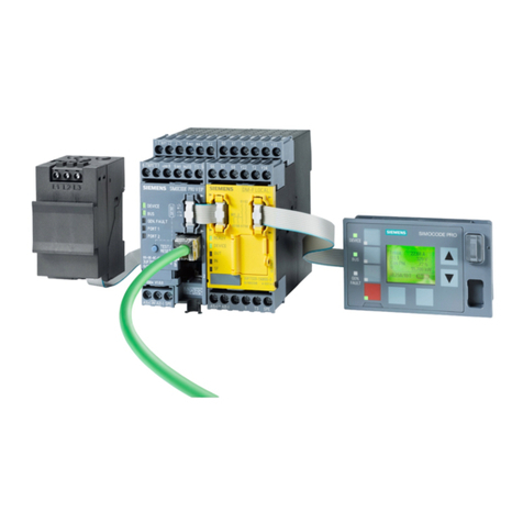
Siemens Cerberus Pyrotronics NIM-1M User manual
Other Siemens Control Unit manuals
Siemens
Siemens SIMATIC PCS 7 User manual
Siemens
Siemens SIRIUS ACT 3SU1400-1EK10-6AA0 User manual
Siemens
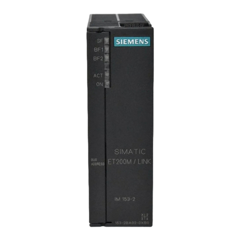
Siemens SIMATIC IM 153-2 User manual
Siemens
Siemens SINUMERIK 840Di sl Quick start guide

Siemens
Siemens FDCI723 User manual

Siemens
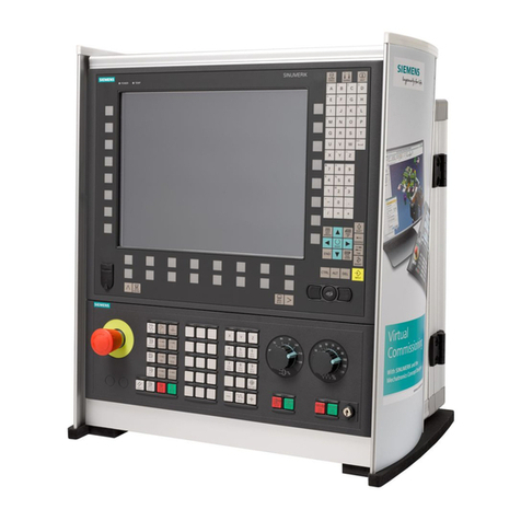
Siemens SINUMERIK 840D sl Quick start guide
Siemens
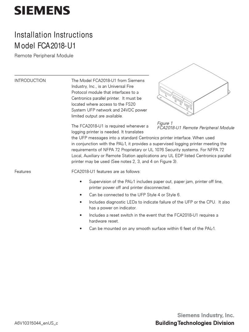
Siemens FCA2018-U1 User manual
Siemens
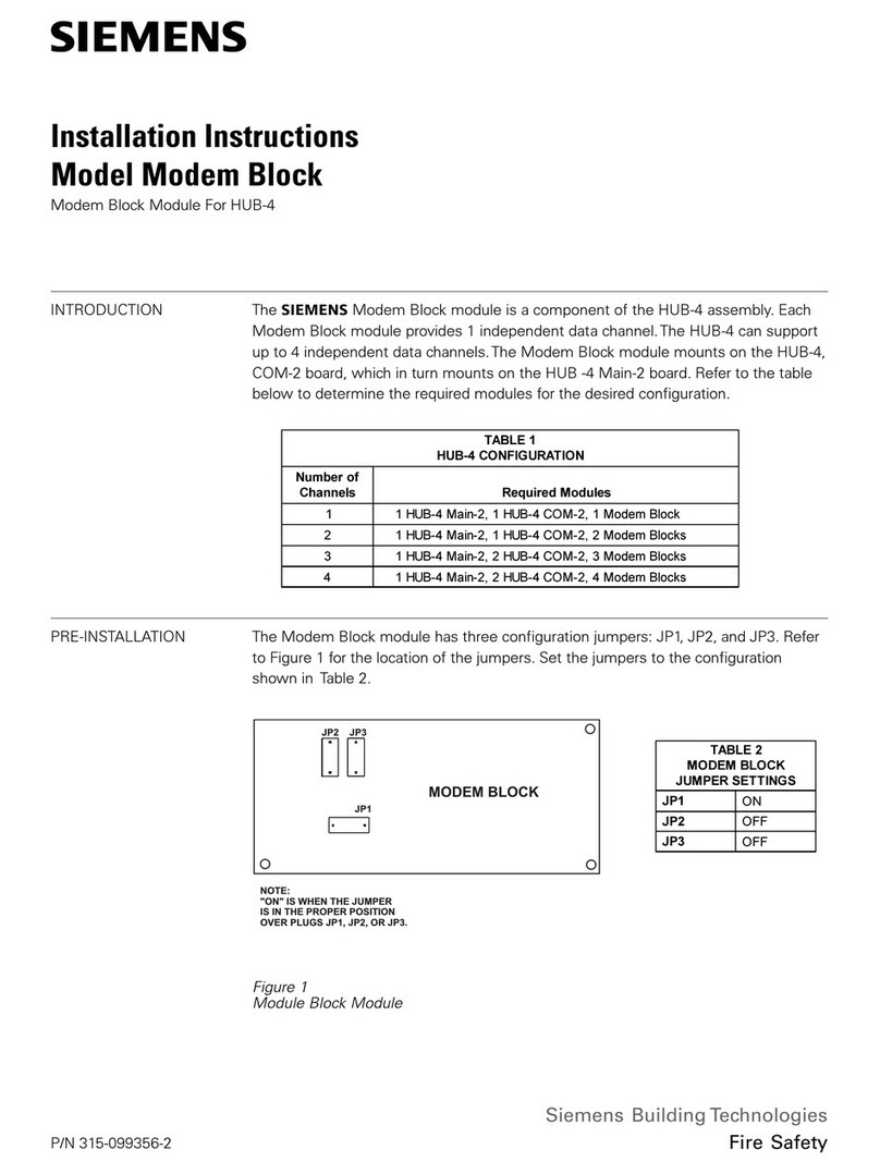
Siemens Modem Block User manual
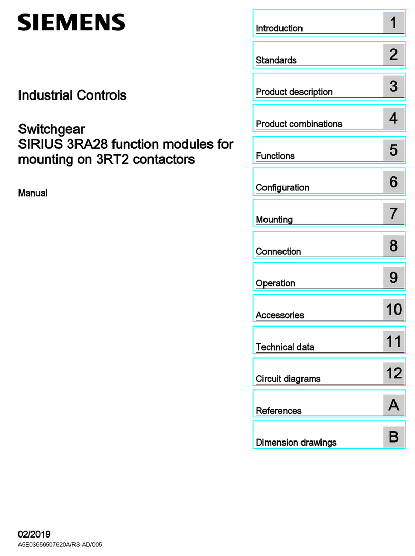
Siemens
Siemens SIRIUS 3RT2 User manual
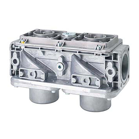
Siemens
Siemens VGD20.253U Owner's manual
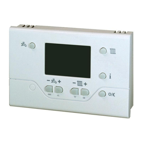
Siemens
Siemens QAA73.210 User manual
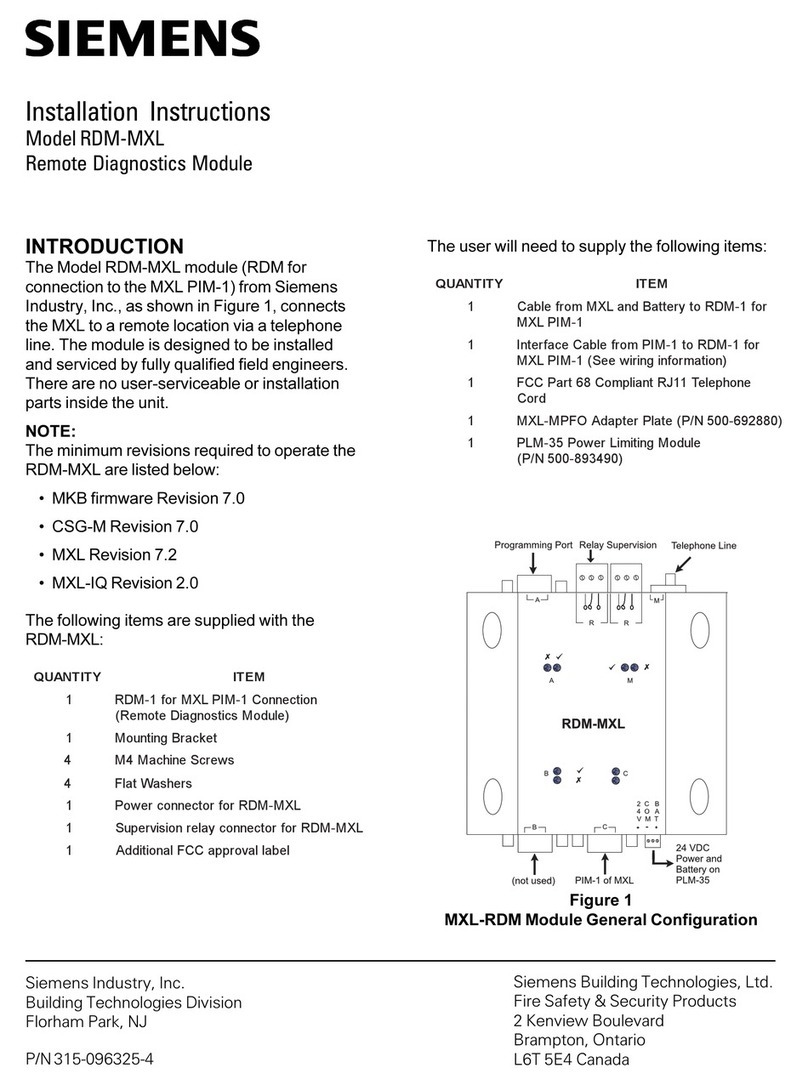
Siemens
Siemens RDM-MXL User manual
Siemens
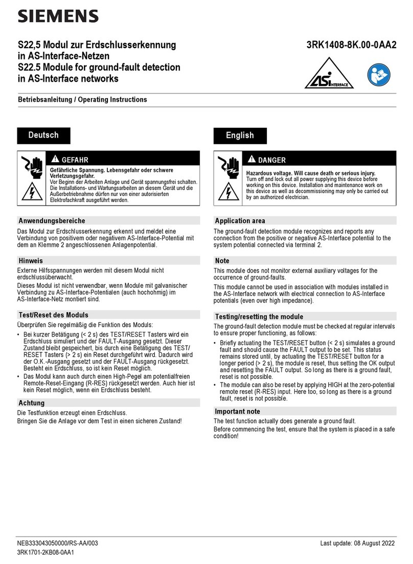
Siemens 3RK1408-8K.00-0AA2 User manual

Siemens
Siemens PXC-16 Compact Product manual

Siemens
Siemens IM 328-N Operating and installation instructions
Siemens
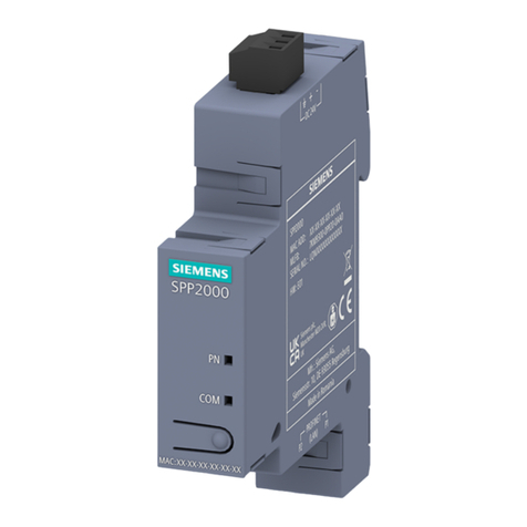
Siemens SENTRON PROFINET Proxy SPP2000 User manual

Siemens
Siemens SINUMERIK 840D sl User manual

Siemens
Siemens MICROMASTER 411 User manual
Siemens
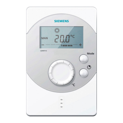
Siemens QAW910 User manual
Siemens
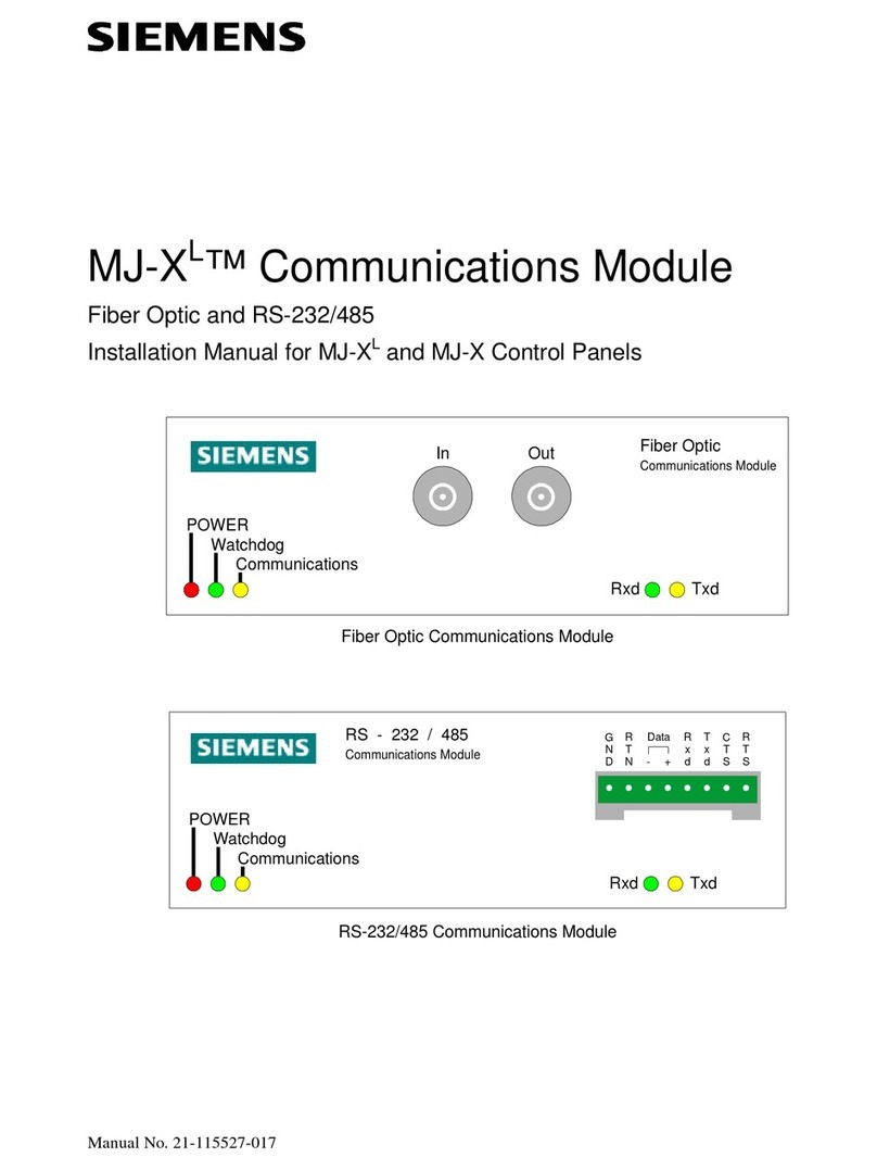
Siemens MJ-XL User manual
Popular Control Unit manuals by other brands

Festo
Festo Compact Performance CP-FB6-E Brief description

Elo TouchSystems
Elo TouchSystems DMS-SA19P-EXTME Quick installation guide

JS Automation
JS Automation MPC3034A user manual

JAUDT
JAUDT SW GII 6406 Series Translation of the original operating instructions

Spektrum
Spektrum Air Module System manual

BOC Edwards
BOC Edwards Q Series instruction manual

KHADAS
KHADAS BT Magic quick start

Etherma
Etherma eNEXHO-IL Assembly and operating instructions

PMFoundations
PMFoundations Attenuverter Assembly guide

GEA
GEA VARIVENT Operating instruction

Walther Systemtechnik
Walther Systemtechnik VMS-05 Assembly instructions

Altronix
Altronix LINQ8PD Installation and programming manual

