manuals.online logo
Brands
  1. Home
  2. •
  3. Brands
  4. •
  5. Siemens
  6. •
  7. Control Unit
  8. •
  9. Siemens TBM-2 User manual

Siemens TBM-2 User manual

Other Siemens Control Unit manuals
Siemens SINAMICS DCM Datasheet

Siemens

Siemens SINAMICS DCM Datasheet

Siemens LOGO! Series User manual

Siemens

Siemens LOGO! Series User manual

Siemens SINAMICS V90 User guide

Siemens

Siemens SINAMICS V90 User guide

Siemens SIPROTEC 7SJ80 User manual

Siemens

Siemens SIPROTEC 7SJ80 User manual

Siemens 3WN 6 3WX3661-0JA00 User manual
Siemens

Siemens 3WN 6 3WX3661-0JA00 User manual

Siemens SINAMICS Series Technical Document

Siemens

Siemens SINAMICS Series Technical Document

Siemens IM 328-N Operating and installation instructions

Siemens

Siemens IM 328-N Operating and installation instructions

Siemens SIMOTION D425 User manual

Siemens

Siemens SIMOTION D425 User manual

Siemens SIDOOR AT40 User guide

Siemens

Siemens SIDOOR AT40 User guide

Siemens MXG461B Series Owner's manual

Siemens

Siemens MXG461B Series Owner's manual

Siemens 8DO User manual

Siemens

Siemens 8DO User manual

Siemens Cerberus Pyrotronics NIM-1M User manual

Siemens

Siemens Cerberus Pyrotronics NIM-1M User manual

Siemens AZL2 Series User manual

Siemens

Siemens AZL2 Series User manual

Siemens M3P FY Series User manual

Siemens

Siemens M3P FY Series User manual

Siemens SIMATIC ET 200S User manual

Siemens

Siemens SIMATIC ET 200S User manual

Siemens SIMATIC S7 300 PLC User manual

Siemens

Siemens SIMATIC S7 300 PLC User manual

Siemens QUADLOG Quick guide

Siemens

Siemens QUADLOG Quick guide

Siemens RWF50 User guide

Siemens

Siemens RWF50 User guide

Siemens SIMATIC IM 151/CPU User manual

Siemens

Siemens SIMATIC IM 151/CPU User manual

Siemens SITOP UPS1600 User manual

Siemens

Siemens SITOP UPS1600 User manual

Siemens VVF Series User manual

Siemens

Siemens VVF Series User manual

Siemens SINUMERIK 840D User manual

Siemens

Siemens SINUMERIK 840D User manual

Siemens SIMATIC NET CP 142-2 User manual

Siemens

Siemens SIMATIC NET CP 142-2 User manual

Siemens Siwarex U Application guide

Siemens

Siemens Siwarex U Application guide

Popular Control Unit manuals by other brands

Seitz 14A80 user manual

Seitz

Seitz 14A80 user manual

Wilo RS485 Installation and operating instructions

Wilo

Wilo RS485 Installation and operating instructions

Becker CentralControl CC41 Commissioning Instruction

Becker

Becker CentralControl CC41 Commissioning Instruction

SICK CDB650 operating instructions

SICK

SICK CDB650 operating instructions

Panduit NetKey NKP5E88M Series installation instructions

Panduit

Panduit NetKey NKP5E88M Series installation instructions

MX Options Concentric Petite Fitting instructions

MX

MX Options Concentric Petite Fitting instructions

Clean Water Systems Fleck 2510 Installation & start?up guide

Clean Water Systems

Clean Water Systems Fleck 2510 Installation & start?up guide

Fairchild FSB44104A user guide

Fairchild

Fairchild FSB44104A user guide

LEGRAND Wattstopper LMIN-104 installation instructions

LEGRAND

LEGRAND Wattstopper LMIN-104 installation instructions

PMK ATT10BNCS instruction manual

PMK

PMK ATT10BNCS instruction manual

Tektronix TDS3FFT user manual

Tektronix

Tektronix TDS3FFT user manual

Woodward easYgen Technical manual

Woodward

Woodward easYgen Technical manual

Balluff BNI EIP-502-105-R015 user guide

Balluff

Balluff BNI EIP-502-105-R015 user guide

NXP Semiconductors TWR-LS1021A Getting started

NXP Semiconductors

NXP Semiconductors TWR-LS1021A Getting started

Advantech PCM-3117 Startup manual

Advantech

Advantech PCM-3117 Startup manual

Danfoss MCO 101 manual

Danfoss

Danfoss MCO 101 manual

Moons' Lin Engineering R701P user manual

Moons'

Moons' Lin Engineering R701P user manual

Aventics RV1 operating instructions

Aventics

Aventics RV1 operating instructions

manuals.online logo
manuals.online logoBrands
  • About & Mission
  • Contact us
  • Privacy Policy
  • Terms and Conditions

Copyright 2025 Manuals.Online. All Rights Reserved.

P/N 315-093782-9
INTRODUCTION
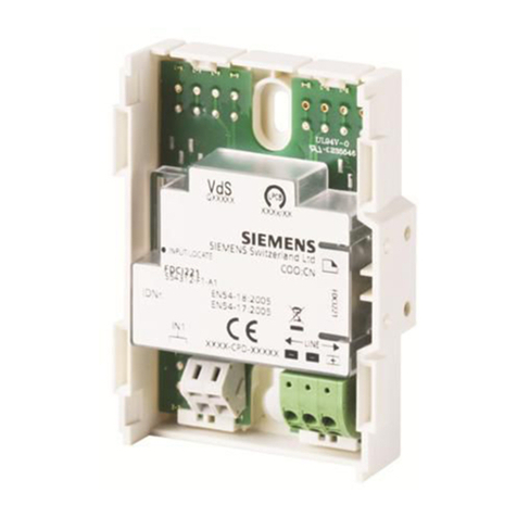
The Model TBM-2 Termination Block module
from Siemens Industry, Inc., is the central
connection point for audio functions in the
MXLV System (See Figure 1). The ACM-1
Audio Control module communicates with
other modules in the system through the
TBM-2. In addition, the TBM-2 has connections
for the recording of telephone and microphone
messages, and the control connections to
activate recording equipment. Refer to the
CSG-M Manual, P/N 315-090381, to select
the Voice Options for your system.
The TBM-2 has two single pole, double throw
(SPDT) dry contacts, AUX CTRL1 and AUX
CTRL2, that control recording equipment.
When the microphone or telephone is active,
the signal goes to the chosen auxiliary output
and the corresponding control output changes
state. The TBM-2 does not include connectors
or cables for connecting the auxiliary outputs
and auxiliary controls.
The TBM-2 has a connection for an external
signal source. Use the AUX IN input and a
VSM-1 function to connect an external signal
source to the MXLV System. See Figure 4 for
information on input signals.
The TBM-2 provides screw terminal blocks
and connectors that interface the internal
wiring and field wiring (See Table 1).
For additional information on the MXL/MXLV
System, refer to the MXL/MXLV Manual, P/N
315-092036.
INSTALLATION
Remove all system power before installation,
first battery and then AC. (To power up, connect
the AC first and then the battery.)
The TBM-2 mounts on the right side of the
backbox next to the MMB or PSR-1, approxi-
mately one-third of the way down from the top
(Refer to Figure 2).
NOTE: In a Remote Extender enclosure the
TBM-2 mounts below the PS-5N7. Refer
to the PS-5N7 Instructions, P/N 315-092729.
Installation Instructions
Model TBM-2
Termination Block Module
TABLE 1
TBM-2 CONNECTIONS
Connector Connects
TB2 Digital Message Unit audio signal
connection
TB5 Supervised riser signals to System
(Style Y or Z)
TB4 Supervised telephone riser signal
(Style Y)
P1 SPDT contact to start the recorder for
AUX OUT 1
P2, P3 Plug-in cable power connections for
ACM-1
P4 Plug-in cable power connection for
VSM-1/VLM-1/VFM-1
P5 Plug-in cable power connections for
TMM-1
P6 SPDT contact to start the recorder for
AUX OUT 2
J1 AUX IN RCA type jack
J2 AUX OUT 1 RCA type jack
J3 AUX OUT 2 RCA type jack
Siemens Industry, Inc.
Building Technologies Division
Florham Park, NJ
Siemens Building Technologies, Ltd.
Fire Safety & Security Products
2 Kenview Boulevard
Brampton, Ontario L6T 5E4 Canada
2
WIRING
Refer to Figures 3 and 4.
All wiring must comply with
national and local codes.
For the audio and telephone risers:
Maximum wire size: 14 AWG twisted
pair, shielded
Minimum wire size: 18 AWG twisted
pair, shielded
Maximum loop resistance: 20 ohms for both
wires
Connect the 24 VDC to TB3 using 14 AWG
single conductor wire. Terminal 1 is for +24
VDC; terminal 2 is for 24 VDC return.
Refer to the CSG-M configuration printout to
determine the wiring style (either Style Y or
Style Z) for terminal block TB5.
For Style Z wiring, make the following connec-
tions:
• Connect terminals 1 and 4 in one cable going
out to Riser 1.
•
Connect terminals 2 and 3 in another cable
coming back from the last destination of
Riser 1.
• The other audio risers connect in a similar
fashion.
For Style Y connections, use only one cable.
Refer to Figure 3 for details.
Figure 1
TBM-2 Termination Block Module
Figure 2
Mounting the TBM-2
NOTE:
In a Remote Extender
enclosure, a PS-5N7 is
mounted above the TBM-2.
1. Before installing the module, mount the
PCB assembly to the mounting bracket
supplied using the four No. 6 screws
provided.
2. Place the TBM-2 assembly face up on the
three threaded studs arranged in a triangle
with TB5, the 15 position terminal block at
the top.
3. Secure the TBM-2 with the three No. 10
nuts provided.
3
Connect the riser cables to TB5 in the desired style,
using 18-14 AWG twisted, shielded pair. The other
ends of the risers connect to the OCC-1 terminal
block. Refer to the OCC-1 Installation Instructions,
P/N 315-090918, for further details.
For connections to other connectors and terminal
blocks, refer to the appropriate module installa-
tion instructions. (See also Figure 3 or Figure 4,
as appropriate.)
CAUTION: Keep the riser cables away from the AC power lines, the 24 VDC
supply lines, and the wires carrying the amplified audio signals.
Figure 3
TBM-2 Wiring Diagram
(with MMB or PSR)
1234
5678 91011 12 13 14 15
12
49 50
TB4
TB3
TB1
P4
TB2
DV-100
OR DMC-1
#1
DV-100
OR DMC-1
#2
+-+-
P2
P5
P3
TB5
J2 J3
J1
P1
NC NC
NO NOC C
P6
1
1
2
2
3
14 14
1
1
TELEPHONE
RISER +
TELEPHONE
RISER -
TELEPHONE
RISER SHIELD
24V DC +
24V DC RETURN
TO ACM-1, P2
50 CONDUCTOR
RIBBON CABLE
TO VSM-1/VLM-1/VFM-1 MODULES
4 WIRE CABLE
TO ACM-1, P3
TO TMM-1, P1
5 WIRE CABLE
4 WIRE CABLE
NO CONNECTIONS
*EOL
*EOL
*EOL
CONNECTION AT FIRST OCC-1 TERMINAL BLOCK
~
~
~
~
~
~
~
~
~
~
~
~
CONNECTION AT SECOND OCC-1 TERMINAL BLOCK
CONNECTION AT LAST OCC-1 TERMINAL BLOCK
AUDIO RISER #1 AUDIO RISER #2
AUDIO RISER #3
CONNECTION AT FIRST OCC-1 TERMINAL BLOCK
CONNECTION AT SECOND OCC-1 TERMINAL BLOCK
CONNECTION AT LAST OCC-1 TERMINAL BLOCK INCLUDES EOL
STYLE Y
STYLE Z
NOT USED
TERMINATED
For Style Z connections, the lines
connected to terminals 1 and 4 are
in one cable. The lines connected
to terminals 2 and 3 are in another
cable. Connect the shield from the
cable connected to terminals 1 and 4.
Telephone Riser
Supervisory Voltage:
15 VDC -
With EOL = 5.6K
and no telephones in
off-hook state.
11 VDC -
With EOL = 5.6K
and one telephone
in off-hook state.
*EOL 10K, 5%, 1/2W
P/N 140-820396
14 AWG SINGLE
CONDUCTOR
14 AWG SINGLE
CONDUCTOR
For all Audio and Telephone Risers
Maximum Loop Resistance: 20 OHMS
Minimum Wire Size: 18 AWG twisted pair, shielded
Maximum Wire Size: 14 AWG twisted pair, shielded
NOTE:
24 VDC IS AVAILABLE ON
THE MMB OR PSR-1
24 VDC IS AVAILABLE ON
THE MMB OR PSR-1
ALL WIRING MUST COMPLY WITH
NATIONAL AND LOCAL CODES
ALL WIRING MUST COMPLY WITH
NATIONAL AND LOCAL CODES
AUX
CTRL 1
AUX
CTRL 2
AUX
IN
AUX
OUT1
AUX
OUT 2
Refer to Wiring Specification
for MXL, MXL-IQ and MXLV
Systems, P/N 315-092772
revision 6 or higher, for
additional wiring information.
Audio Riser
Supervisory Voltage:
3.65 VDC nominal
1V RMS AC
POSITIVE AND NEGATIVE GROUND FAULT DETECTED AT <50K OHMS FOR TERMINALS 1-14.
P/N 315-093782-9
Figure 4
TBM-2 Wiring Diagram
(with PS-5N7 in an Extender Enclosure)
WARNING
The user must comply with AUX IN and AUX OUT
specifications or the MXLV System may not function
properly. Always complete the full system test to
ensure that all applications function completely.
NOTES
1. All wiring must comply with National and Local codes.
2. For all Audio and Telephone Risers:
Maximum Loop Resistance: 20 ohms
Minimum Wire Size: 18 AWG twisted pair,
shielded
Maximum Wire Size: 14 AWG twisted pair,
shielded
3. Input impedance of AUX IN is 3K ohms, 200mV RMS.
4. The signal source must have isolation using a transformer.
5. The load impedance for AUX OUT must not be less than 10K
ohms, 200mV RMS.
6. The load must have isolation using a transformer.
7. SPDT contacts activate when audio is present on AUX OUT
jacks based on the CSG-M selection of microphone or tele-
phone. Contact ratings: 0.3A at 24 VDC
• If AUX OUT 1 is microphone, then AUX OUT 2 is telephone.
• If AUX OUT 1 is telephone, then AUX OUT 2 is microphone.
8. Refer to Wiring Specification for MXL, MXL-IQ and MXLV
Systems, P/N 315-092772 revision 6 or higher, for additional
wiring information.
ELECTRICAL RATINGS
tnerruCeludoMCDV5evitcAAm0
tnerruCeludoMCDV42evitcAAm76
tnerruCeludoMCDV42ybdnatSAm06