manuals.online logo
Brands
  1. Home
  2. •
  3. Brands
  4. •
  5. Siemens
  6. •
  7. Controllers
  8. •
  9. Siemens Flowrite 599 Series User manual

Siemens Flowrite 599 Series User manual

Other manuals for Flowrite 599 Series

12

This manual suits for next models

9

Other Siemens Controllers manuals

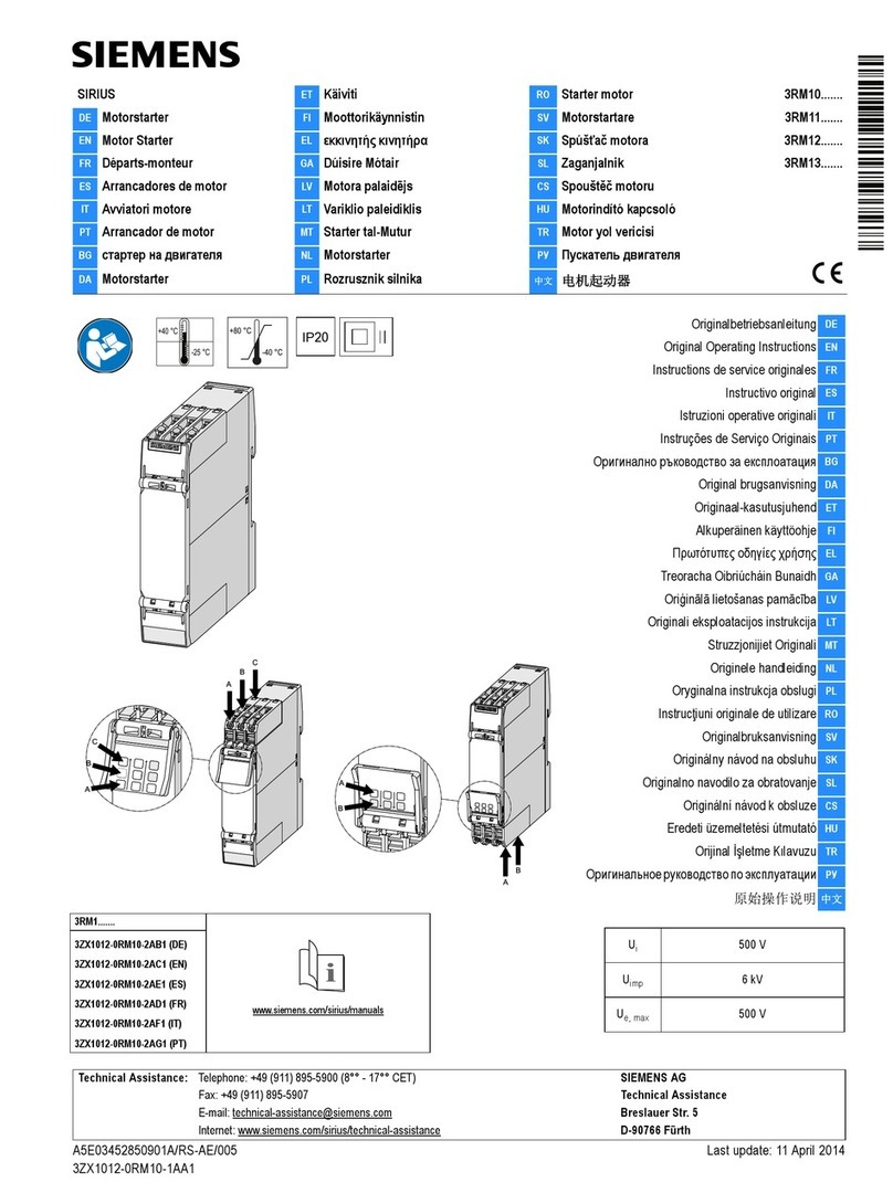
Siemens OpenAir GND12x.1 Series Service manual

Siemens

Siemens OpenAir GND12x.1 Series Service manual

Siemens Simatic SM331 User manual

Siemens

Siemens Simatic SM331 User manual

Siemens RDU340 Series Operator's manual

Siemens

Siemens RDU340 Series Operator's manual

Siemens SIMOTION D410 Quick start guide

Siemens

Siemens SIMOTION D410 Quick start guide

Siemens GLB 9E Series User manual

Siemens

Siemens GLB 9E Series User manual

Siemens SINAMICS S120 User manual

Siemens

Siemens SINAMICS S120 User manual

Siemens ACVATIX SKB Series User manual

Siemens

Siemens ACVATIX SKB Series User manual

Siemens RAJA+ 3TE7121-1HC14-1A Series Guide

Siemens

Siemens RAJA+ 3TE7121-1HC14-1A Series Guide

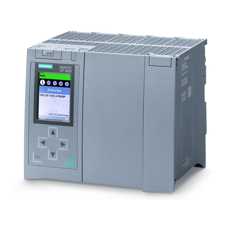
Siemens Simatic S7-1500 User manual

Siemens

Siemens Simatic S7-1500 User manual

Siemens OpenAir E Series User manual

Siemens

Siemens OpenAir E Series User manual

Siemens SIPART DR22 User manual

Siemens

Siemens SIPART DR22 User manual

Siemens SIMOCODE pro User guide

Siemens

Siemens SIMOCODE pro User guide

Siemens Flowrite 599 Series Owner's manual

Siemens

Siemens Flowrite 599 Series Owner's manual

Siemens Gamma instabus UP204 Contouch Service manual

Siemens

Siemens Gamma instabus UP204 Contouch Service manual

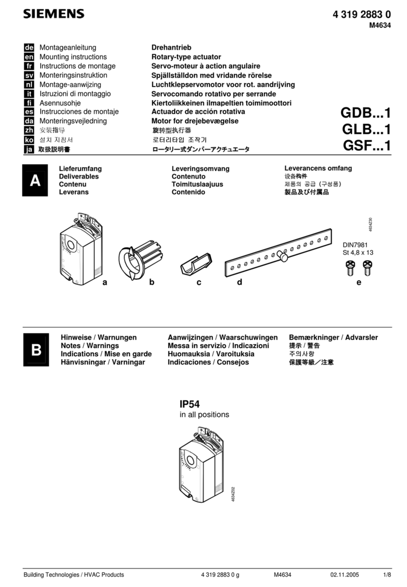
Siemens GDB 1 Series User manual

Siemens

Siemens GDB 1 Series User manual

Siemens S7-1200 TELECONTROL User manual

Siemens

Siemens S7-1200 TELECONTROL User manual

Siemens SINUMERIK 840D Operating instructions

Siemens

Siemens SINUMERIK 840D Operating instructions

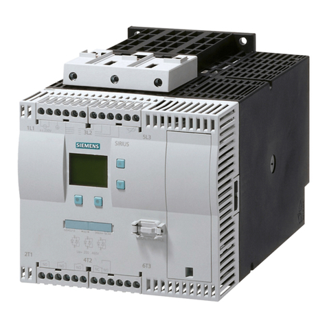
Siemens SIKOSTART 3RW35 Manual

Siemens

Siemens SIKOSTART 3RW35 Manual

Siemens RBC User manual

Siemens

Siemens RBC User manual

Siemens Simatic S7-1500 User guide

Siemens

Siemens Simatic S7-1500 User guide

Siemens SINUMERIK 840D sl User guide

Siemens

Siemens SINUMERIK 840D sl User guide

Siemens SIPART DR20 Technical manual

Siemens

Siemens SIPART DR20 Technical manual

Siemens OpenAir GLB 1E Series User manual

Siemens

Siemens OpenAir GLB 1E Series User manual

Siemens 5WG1 523-1AB04 User manual

Siemens

Siemens 5WG1 523-1AB04 User manual

Popular Controllers manuals by other brands

Sunricher SR-ZV9003T3-RGBW-US Installation

Sunricher

Sunricher SR-ZV9003T3-RGBW-US Installation

Ksenia intro Installation and configuration manual

Ksenia

Ksenia intro Installation and configuration manual

Inovance CAN200 Series manual

Inovance

Inovance CAN200 Series manual

Gauzy LC6 FLEX Controller Installation and operation guide

Gauzy

Gauzy LC6 FLEX Controller Installation and operation guide

Viking SLP-1 Technical practice

Viking

Viking SLP-1 Technical practice

CKD KBX-30E-U Series instruction manual

CKD

CKD KBX-30E-U Series instruction manual

Sharp Energy Sun Flux User manual & installation guide

Sharp Energy

Sharp Energy Sun Flux User manual & installation guide

Yamaha RCX40 user manual

Yamaha

Yamaha RCX40 user manual

AB Quality PowerFlex 400 Frames D-H Service bulletin

AB Quality

AB Quality PowerFlex 400 Frames D-H Service bulletin

Yamaha MJC8 owner's manual

Yamaha

Yamaha MJC8 owner's manual

AL-KO ATC operating instructions

AL-KO

AL-KO ATC operating instructions

Savant SmartControl 2 Deployment guide

Savant

Savant SmartControl 2 Deployment guide

GameSir T3S user manual

GameSir

GameSir T3S user manual

Kostal inveor operating manual

Kostal

Kostal inveor operating manual

Emerson Yarway 20-55 Operating and safety instructions

Emerson

Emerson Yarway 20-55 Operating and safety instructions

CoCo ACM-LV24 Quick installation guide

CoCo

CoCo ACM-LV24 Quick installation guide

Brooks SLA5810/20 Installation and operation manual

Brooks

Brooks SLA5810/20 Installation and operation manual

SIGMA TEK SR 011 Technical manual

SIGMA TEK

SIGMA TEK SR 011 Technical manual

manuals.online logo
manuals.online logoBrands
  • About & Mission
  • Contact us
  • Privacy Policy
  • Terms and Conditions

Copyright 2025 Manuals.Online. All Rights Reserved.

599 Series Zone Valves
SFA/SFP Electronic Valve Actuator
2-Position Control
Installation Instructions
Document No. 129-335
June 22, 2005
EA0961R1
Product Description
The SF Series actuator requires a 24 Vac, 120 Vac, 208 Vac,
or 277 Vac Class-2 supply signal to control Siemens Zone
Valves with a 1/10-inch (2.5 mm) stroke.
Warning/Caution Notations
WARNING:
Personal injury or loss of life
may occur if you do not follow
a procedure as specified.
CAUTION:
Equipment damage, or loss of
data may occur if you do not
follow a procedure as
specified.
Product Numbers
Actuator
Model Power
Supply Actuator
Code
SFP71U 24 Vac 243
SFP11U 120 Vac 241
SFP277U/25 277 Vac – *
Normally
Open
SFP208U/25 208 Vac – *
SFA71U 24 Vac 242
SFA11U 120 Vac 240
SFA208U/25 208 Vac – *
Normally
Closed
SFA277U/25 277 Vac – *
* Actuator only with 2.5-meter cable, not available
as an assembly.
Contents
One actuator
Required Tools
• Small flat-blade screwdriver
• Wire stripper
Estimated Installation Time
20 minutes
EA0959R1
Figure 1. Acceptable Mounting Positions.
The vertical position is recommended for mounting.
Prerequisites
WARNING:
1. If mounting the actuator to a valve already
in line:
• Close the shut-off valves in the piping
(upstream first, then downstream).
Or
• Switch off the pump to allow the
differential pressure in the valve to
drop.
2. Disconnect the controller power before
replacing the actuator.
Installation
Mounting the SFP Actuator to a Valve
1. Place the actuator on the valve and firmly hand-tighten the
coupling piece.
2. Connect the wires. See Wiring.
Mounting the SFA Actuator on a Valve
CAUTION:
The black actuator attachment support ring
must be in place on top of the valve bonnet
before installing the actuator.
If the support ring is not in place, damage to
the actuator connection may result.
1. Rotate the manual override lever and latch.
2. Place the actuator on the valve and firmly hand-tighten
the coupling piece.
CAUTION:
Failure to fully rotate the manual override
handle before hand tightening will hinder
proper valve close off.
3. Release manual override handle.
4. Connect the wires. See Wiring.
Item Number 129-335, Rev. 015 Page 1 of 4
Document No.129-335
Installation Instructions
June 22, 2005
VE0268R1
12
Figure 2. Mounting the Actuator on a Valve.
The installation is now complete.
Removing the Actuator from a Valve
1. Disconnect the wiring.
2. Unscrew actuator-coupling piece from the valve body
threads.
3. Remove the actuator from the valve.
Wiring
• All wiring must conform to NEC and local codes and
regulations.
• Use earth ground isolating step-down Class 2
transformers.
NOTE: Do not use autotransformers.
• Determine the supply transformer rating by summing
the total VA of all actuators used. The maximum
rating for a Class 2 step-down transformer is 100 VA.
NOTE: It is recommended that one transformer power
no more than 10 actuators.
• SFA71U/SFP71U 24 Vac actuators: Wiring
connection can be made inside the actuator housing
(remove the housing top for access).
• Line voltage actuators: Wiring connection requires
junction box and flex conduit no further than
15 inches (381 mm) from actuator.
G
G0
(Red)
(Black)
24 Vac
Neutral
EA0993R2
CAUTION:
G0 and G must be properly wired for correct
function and full life of the actuator.
Figure 3. 24 Vac Actuator Wiring Diagram.
L
N
(Black)
(White)
120 Vac
Neutral
(Green)
GND
EA1036R2
Figure 4. 120 Vac Actuator Wiring Diagram.
L
N
(Red)
(White)
208 Vac
208 Vac
(Green)
GND
EA1140R1
Figure 5. 208 Vac Actuator Wiring Diagram.
L
N
Neutral
(Blue)
(White)
277 Vac
(Green)
GND
EA1139R1
Figure 6. 277 Vac Actuator Wiring Diagram.
Page 2 of 4 Siemens Building Technologies, Inc.
Document No. 129-335
Installation Instructions
June 22, 2005
Manual Override
For manual positioning, rotate the manual override handle
clockwise 180°, and squeeze it to latch around protruding stop.
See Figure 7.
NOTE: The actuator will automatically unlatch when power
is applied.
VE0986R1
01
01
Override
handle at
position 0.
Override
handle at
position 1.
Figure 7. Manual Override Handle Position.
When the manual override handle is at the "0" position, the
output shaft is retracted if the actuator is normally open, or
extended if normally closed. See Figure 8.
When the Manual Override handle is rotated to
position 1, the reverse is true. See Figure 9.
Start-Up
Check the wiring and the position indication.
EA0987R1
BA
B
A
(A) Allow handle to turn counterclockwise to retract spindle.
(B) Turn handle clockwise to extend spindle.
CAUTION:
To avoid damage to actuator, DO
NOT manually assist spring return.
Figure 8. Normally Open. (SFP Series).
EA0987R1
BA
B
A
NOTE:
The "0" and "1" position
markings are intended
for reference only and
not stroke
measurement.
(A) Allow handle to turn counterclockwise to extend spindle.
(B) Turn handle clockwise to retract spindle.
CAUTION:
To avoid damage to actuator, DO
NOT manually assist spring return.
Figure 9. Normally Closed (SFA Series).
Troubleshooting
Check the wiring for the proper connections.
References
Technical Instructions Document Number
SFA/SFP Electronic Valve Actuator 155-321P25
24 Vac or 120 Vac, 2-Position Control
Zone Valve Assemblies TB254 155-291
Siemens Building Technologies, Inc. Page
3 of 4
Document No.129-335
Installation Instructions
June 22, 2005
Dimensions
EA0258R1
2.3
(58)
4.4
(111)
3.4
(85.2)
Figure 10. Dimensions of the SF Series Actuator Shown in Inches (Millimeters).
Service Envelope
Minimum access space recommended: 8 inches (200 mm) above the actuator.
Information in this publication is based on current specifications. The company reserves the right to make changes in specifications and models as
design improvements are introduced. Other product or company names mentioned herein may be the trademarks of their respective owners.
© 2005 Siemens Building Technologies, Inc.
Siemens Building Technologies, Inc.
1000 Deerfield Parkway Your feedback is important to us. If you have
comments about this document, please send
Buffalo Grove, IL 60089-4513
U.S.A. them to [email protected]
Page 4of 4
Document No. 129-335
Country of Origin: US