manuals.online logo
Brands
  1. Home
  2. •
  3. Brands
  4. •
  5. Siemens
  6. •
  7. Controllers
  8. •
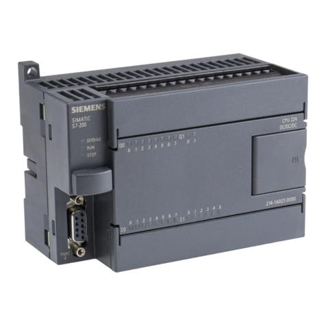
  9. Siemens Simatic S7-300 Assembly Instructions

Siemens Simatic S7-300 Assembly Instructions

Preface, Contents
Product Overview 1
Mechanical Configuration 2
Addressing the S7-300 Modules 3
Electrical Configuration 4
Installing an S7-300 5
Wiring an S7-300 6
Configuring an MPI or
PROFIBUS Subnet 7
Preparing an S7-300 for
Operation and Start-up of
PROFIBUS-DP 8
Changing the Backup Battery/
Rechargeable Battery, Module
and Fuses 9
CPUs 10
CPU 315-2 DP as DP Master/
DP Slave 11
Cycle Time and Response Time
of the S7-300 12
Appendices
Glossary, Index
Edition 2
EWA 4NEB 710 6078-02a
S7-300 Programmable Controller
Installation and Hardware
Manual
SIMATIC
This
Manual is Part of the Documentation Package
with the Order Number:
6ES7 398-8AA02-8BA0
ii
S7-300,
Installation and Hardware
EW
A 4NEB 710 6078 02
This manual contains notices which you should observe to ensure your own personal safety, as
well as to protect the product and connected equipment. These notices are highlighted in the
manual by a warning triangle and are marked as follows according to the level of danger:
!Danger
indicates that death, severe personal injury or substantial property damage will result if proper
precautions are not taken.
!Warning
indicates that death, severe personal injury or substantial property damage can result if proper
precautions are not taken.
!Caution
indicates
that minor personal injury or property damage can result if proper precautions are not
taken.
Note
draws
your attention to particularly important information on the product, handling the product, or
to a particular part of the documentation.
Only qualified personnel should be allowed to install and work on this equipment. Qualified
persons are defined as persons who are authorized to commission, to ground, and to tag circuits,
equipment, and systems in accordance with established safety practices and standards.
Note the following:
!Warning
This
device and its components may only be used for the applications described in the
catalog or the
technical
description, and only in connection with devices or components from other manufacturers
which have been approved or recommended by Siemens.
This
product can only function correctly and safely if it is transported, stored, set up, and installed
correctly, and operated and maintained as recommended.
SIMATIC
and SIMATIC NETare registered trademarks of SIEMENS AG.
Third
parties using for their own purposes any other names in this document which refer to trade
-
marks might infringe upon the rights of the trademark owners.
We
have checked the contents of this manual for agreement with
the
hardware
and software described. Since deviations cannot be pre
-
cluded
entirely
, we cannot guarantee full agreement. However
, the
data in this manual are reviewed regularly and any necessary
corrections included in subsequent editions. Suggestions for im-
provement
are welcomed.
T
echnical data subject to change.

Siemens
AG 1994
Disclaimer of Liability
Copyright

Siemens
AG 1994 All rights reserved
The reproduction, transmission or use of this document or its
contents is not permitted without express written authority.
Offenders will be liable for damages. All rights, including rights
created
by patent grant
or registration of a utility model or design, are
reserved.
Siemens
AG
Automation Group
Industrial Automation Systems
P
.O. Box 4848,
D-90327 Nuremberg
Siemens Aktiengesellschaft
Safety
Guidelines
Qualified Personnel
Correct Usage
Trademarks
iii
S7-300,
Installation and Hardware
EW
A 4NEB 710 6078-02a
Preface
The
information contained in this manual will help you with the following:

Install and wire an S7-300 programmable controller
, and

Look up operator entries, functional descriptions and the technical speci
-
fications relevant to the S7-300’
s CPUs.
Y
ou will find the function descriptions and technical specifications for the
signal modules, power supply modules and interface modules in the
Mod-
ule Specifications Refer
ence Manual.
This documentation package with the order number 6ES7 398-8AA02-8BA0
comprises two manuals and an instruction list with the following contents:
S7-300 Programmable Controller
,
Hardware and Installation

Mechanical and electrical config
-
uration

Installation and wiring

Preparing the S7-300 for opera
-
tion

Characteristics and technical
data for the S7-300 CPUs

General technical data

Power supply modules

Digital modules

Analog modules

Order numbers for
S7-300
S7-300, M7-300 Programmable
Controllers, Module Specifications
Instruction List

Instruction set for all CPUs

Brief description of instruc
-
tions and execution times
in relation to the individual
CPUs
A detailed description of all in
-
structions with examples can
be found in the
STEP 7 Manu
-
als
(see Appendix G).
Y
ou can also order the Instruc
-
tion List separately:
6ES7 398-8AA02-8BN0
Purpose of this
Manual
Documentation
Package
iv S7-300,
Installation and Hardware
EW
A 4NEB 710 6078-02a
This
manual applies for the following CPUs:
CPU Order No. From
Version
CPU 312 IFM 6ES7 312-5AC01-0AB0 01
CPU 313 6ES7 313-1AD02-0AB0 01
CPU 314 6ES7 314-1AE03-0AB0 01
CPU 314 IFM 6ES7 314-5AE02-0AB0 01
CPU 315 6ES7 315-1AF02-0AB0 01
CPU 315-2 DP 6ES7 315-2AF02-0AB0 01
CPU 316 6ES7 316-1AG00-0AB0 01
This
manual describes all modules that are valid at the time the manual is
released. For new modules or newer versions of modules, we reserve the op
-
tion to add to the manual a product information containing the current infor
-
mation on this module.
The following changes have been made since the previous version (
S7-300
Pr
ogrammable Contr
oller
, Har
dwar
e and Installation Manual
, Order No.
6ES7 398-8AA01-8BA0, Edition 1):

The CPU 316 has been included in the manual

The CPUs have been expanded with the following functions:
–
19.2 kbaud for the MPI
–
Forcing of variables
–
SFC “RD_DP
ARM”
–
Password protection
–
Cycle time limiting for test functions
–
HOLD mode
–
Downloading of a user program from the programming device via the
CPU onto a memory card and the possibility of updating the operating
system via memory card (not for CPUs 312 IFM and 314 IFM).
The S7-300 programmable controller meets the requirements and criteria of
standard IEC 1
131, Part 2. The S7-300 meets the requirements for the CE
mark. Approvals for CSA, UL and FM have been granted for the S7-300.
See Appendix A for detailed information on standards and approvals.
Scope of this
Manual
Changes Since the
Previous V
ersion
Standards and Ap
-
provals
Preface
v
S7-300,
Installation and Hardware
EW
A 4NEB 710 6078-02a
The
SIMA
TIC S7-300 is an environmentally-friendly product!
The essential features of the SIMA
TIC S7-300 include:

A halogen-free flameproofing of the plastic housing despite its high level
of fireproofing

Laser labeling (that is, no paper labels)

Plastics materials labeled in accordance with DIN 54840

Reduction in materials used thanks to more compact design and fewer
components through integration in ASICs
The SIMA
TIC S7-300 can be recycled thanks to the low level of pollutants in
its equipment.
Please contact the following address for environmentally-friendly recycling
and disposal of your old SIMA
TIC equipment:
Siemens Aktiengesellschaft
Anlagenbau und T
echnische Dienstleistungen
A
TD TD 3 Kreislaufwirtschaft
Postfach 32 40
D-91050 Erlangen
T
elephone: ++ 49 91 31/7-3 36 98
T
elefax: ++ 49 91 31/7-2 66 43
This Siemens service department provides a comprehensive and flexible dis
-
posal system with customized advice at a fixed price. After disposal, you
receive a breakdown of the dismantling procedure with information on the
proportions of materials and the relevant material record documentation.
Recycling
and Dis
-
posal
Preface
vi S7-300,
Installation and Hardware
EW
A 4NEB 710 6078-02a
Depending
on the CPU, you require the following documentation for instal
-
ling your S7-300:
Hardware and
Installation
,
Manual
Reference
Manual
Module
Specs.
Instruction
List
Documentation package
Order No. 6ES7
398-8AA02-0BA0
The following documentation is required for installing the S7-300 and for preparing it for
operation:
For CPUs 312 IFM and 314 IFM, you will also require the description of the inte
-
grated functions and the control functions in STEP 7:
Integrated
Functions
Manual
System and Standard
Functions
Reference Manual
Order No. 6ES7 398-8CA00-8BA0
Order No. 6ES7 810-4CA02-4BR0
Appendix G contains a list of documentation, which you require for program
-
ming and starting up the S7-300. In addition, you will find a list of specialist
books on programmable controls.
Furthermore, the complete SIMA
TIC S7 documentation will be available on
CD-ROM.
T
o help you find special information quickly
, the manual contains the follow
-
ing access aids:

At the start of the manual you will find a complete table of contents and a
list of the diagrams
and tables that appear in the manual.

An overview of the contents of each section is provided in the left column
on each page of
each chapter
.
Y
ou will find a glossary in the appendix at the end of the manual. The
glossary contains definitions of the main technical terms used in the
manual.

At the end of the manual you will find a
comprehensive index which
gives you fast access to the information you need.
Scope of the Docu-
mentation Package
Documentation for
Programming
CD-ROM
How to use this
Manual
Preface
vii
S7-300,
Installation and Hardware
EW
A 4NEB 710 6078-02a
Please
contact your local Siemens representative if you have any queries
about the products described in this manual. A list of Siemens representatives
worldwide is contained in the appendix to this manual.
If you have any questions or suggestions concerning this manual, please fill
in the form at the end of this manual and return it to the specified address.
Please feel free to enter your personal assessment of the manual in the form
provided.
W
e of
fer a range of courses to help get you started with the SIMA
TIC S7 pro
-
grammable controller
. Please contact your local training center or the central
training center in Nurember
g, D-90327 Germany
, T
el. +49 91
1 895 3154.
Y
ou can receive up-to-date information on SIMA
TIC products from the fol
-
lowing sources:

On the Internet at http://www
.ad.siemens.de/
V
ia fax polling number +49–8765-93 00-55 00
In addition, the SIMA
TIC Customer Support provides up-to-date information
and download facilities for users of SIMA
TIC products:

On the Internet at http://www
.ad.siemens.de/simatic–cs
V
ia the SIMA
TIC Customer Support mailbox under the following num
-
ber: +49 - 91
1 - 895 - 7100
For dialing into the mailbox, use a modem of up to V
.34 (28.8 Kbaud) and
set the following parameters: 8, N, 1, ANSI, or alternatively use ISDN
(x.75, 64 Kbit).
Y
ou can reach the SIMA
TIC Customer Support by telephone at
+49 (91
1) 895-7000 and by fax at +49 (91
1) 895-7002. Queries can also be
addressed to us by Internet mail or by mail to the mailbox specified above.
Additional
Assis
-
tance
Up-to-date
Information
Preface
viii S7-300,
Installation and Hardware
EW
A 4NEB 710 6078-02a
Preface
ix
S7-300, Installation and Hardware
EW
A 4NEB 710 6078-02a
Contents
Preface
1 Product
Overview
2 Mechanical Configuration
2.1
Horizontal and V
ertical Arrangement of an S7-300
2-2.
. . . . . . . . . . . . . . . . . . .
2.2 Mounting
Dimensions of the S7-300
2-3.
. . . . . . . . . . . . . . . . . . . . . . . . . . . . . . .
2.3 The
Module Arrangement for an S7-300 Configuration on One Rack
2-6.
. . .
2.4 The
Module Arrangement for an S7-300 Configuration on Several Racks
(not CPU 312 IFM/313)
2-7.
. . . . . . . . . . . . . . . . . . . . . . . . . . . . . . . . . . . . . . . . . .
3 Addressing the S7-300 Modules
3.1
Slot-Oriented Addressing for Modules (Default Addressing)
3-2.
. . . . . . . . . . .
3.2 User-Oriented
Address Allocation with the CPU 315-2 DP
3-4.
. . . . . . . . . . . .
3.3 Addressing
Signal Modules
3-7.
. . . . . . . . . . . . . . . . . . . . . . . . . . . . . . . . . . . . . . .
3.4 Addressing
the Integrated Inputs and Outputs of the CPUs 312 IFM and
314 IFM 3-10.
. . . . . . . . . . . . . . . . . . . . . . . . . . . . . . . . . . . . . . . . . . . . . . . . . . . . . . .
4 Electrical Configuration
4.1
General Rules and Guidelines for Operating an S7-300
Programmable Controller
4-2.
. . . . . . . . . . . . . . . . . . . . . . . . . . . . . . . . . . . . . . . .
4.2 Current
Consumption and Power Losses of an S7-300
4-4.
. . . . . . . . . . . . . . .
4.3 Configuring
the S7-300 Process Peripherals
4-8.
. . . . . . . . . . . . . . . . . . . . . . . .
4.4 S7-300
Configuration with Grounded Reference Potential
4-12.
. . . . . . . . . . . .
4.5 S7-300
Configuration with Ungrounded Reference Potential
(not CPU 312 IFM)
4-13.
. . . . . . . . . . . . . . . . . . . . . . . . . . . . . . . . . . . . . . . . . . . . . .
4.6 S7-300
Configuration with Isolated Modules
4-14.
. . . . . . . . . . . . . . . . . . . . . . . .
4.7 Configuration
of an S7-300 with Non-Isolated Modules
4-16.
. . . . . . . . . . . . . . .
4.8 Cabling
Inside Buildings
4-17.
. . . . . . . . . . . . . . . . . . . . . . . . . . . . . . . . . . . . . . . . .
4.9 Cabling
Outside Buildings
4-20.
. . . . . . . . . . . . . . . . . . . . . . . . . . . . . . . . . . . . . . . .
4.10 Protecting
Digital Output Modules Against Induced Overvoltage
4-21.
. . . . . . .
4.11 Lightning
Protection
4-23.
. . . . . . . . . . . . . . . . . . . . . . . . . . . . . . . . . . . . . . . . . . . . .
4.11.1 Lightning
Protection Zone Concept
4-24.
. . . . . . . . . . . . . . . . . . . . . . . . . . . . . . . .
4.11.2 Rules for the T
ransition between Lightning Protection Zones 0

1
4-26.
. . . .
4.11.3 Rules for T
ransition between Lightning Protection Zones 1

2 and
Greater 4-28.
. . . . . . . . . . . . . . . . . . . . . . . . . . . . . . . . . . . . . . . . . . . . . . . . . . . . . . . .
4.11.4 Example
Circuit for Surge Protection of Networked S7-300s
4-31.
. . . . . . . . . .
x
S7-300, Installation and Hardware
EW
A 4NEB 710 6078-02a
5 Installing
an S7-300
5.1
Installing the Rail
5-2.
. . . . . . . . . . . . . . . . . . . . . . . . . . . . . . . . . . . . . . . . . . . . . . . .
5.2 Module
Accessories
5-5.
. . . . . . . . . . . . . . . . . . . . . . . . . . . . . . . . . . . . . . . . . . . . .
5.3 Installing
the Modules on the Rail
5-6.
. . . . . . . . . . . . . . . . . . . . . . . . . . . . . . . . .
5.4 Identifying
the Modules with Slot Numbers
5-9.
. . . . . . . . . . . . . . . . . . . . . . . . .
6 Wiring
an S7-300
6.1
Wiring Rules
6-2.
. . . . . . . . . . . . . . . . . . . . . . . . . . . . . . . . . . . . . . . . . . . . . . . . . . .
6.2 Wiring
the Power Supply Module and CPU
6-3.
. . . . . . . . . . . . . . . . . . . . . . . . .
6.3 Setting
the Power Supply V
oltage Selector Switch
6-5.
. . . . . . . . . . . . . . . . . . .
6.4 Wiring
the Front Connectors of the Signal Modules
6-6.
. . . . . . . . . . . . . . . . . .
6.5 Connecting
Shielded Cables Using the Shield Connecting Element
6-10.
. . . .
7 Configuring
an MPI or PROFIBUS Subnet
7.1
Configuring a Subnet
7-2.
. . . . . . . . . . . . . . . . . . . . . . . . . . . . . . . . . . . . . . . . . . . .
7.1.1 Basic
Principles
7-3.
. . . . . . . . . . . . . . . . . . . . . . . . . . . . . . . . . . . . . . . . . . . . . . . . .
Special
Considerations for CPs and FMs
7-5.
. . . . . . . . . . . . . . . . . . . . . . . . . . .
7.1.2 Rules
for Configuring a Subnet
7-7.
. . . . . . . . . . . . . . . . . . . . . . . . . . . . . . . . . . .
7.1.3 Cable
Lengths
7-14.
. . . . . . . . . . . . . . . . . . . . . . . . . . . . . . . . . . . . . . . . . . . . . . . . . .
7.2 Network
Components
7-18.
. . . . . . . . . . . . . . . . . . . . . . . . . . . . . . . . . . . . . . . . . . . .
7.2.1 PROFIBUS
Bus Cable
7-19.
. . . . . . . . . . . . . . . . . . . . . . . . . . . . . . . . . . . . . . . . . . .
7.2.2 Bus
Connectors
7-21.
. . . . . . . . . . . . . . . . . . . . . . . . . . . . . . . . . . . . . . . . . . . . . . . . .
7.2.3 Plugging
the Bus Connector into a Module
7-22.
. . . . . . . . . . . . . . . . . . . . . . . . .
7.2.4 RS
485 Repeater
7-23.
. . . . . . . . . . . . . . . . . . . . . . . . . . . . . . . . . . . . . . . . . . . . . . .
8 Preparing
an S7-300 for Operation and Start-up of PROFIBUS-DP
8.1
Plugging in the Memory Card (Not CPU 312 IFM/314 IFM)
8-2.
. . . . . . . . . . .
8.2 Inserting
the Backup Battery/Rechargeable Battery (Not CPU 312 IFM)
8-4.
8.3 Connecting
a Programming Device
8-6.
. . . . . . . . . . . . . . . . . . . . . . . . . . . . . . . .
8.3.1 Connecting
a Programming Device to an S7-300
8-7.
. . . . . . . . . . . . . . . . . . . .
8.3.2 Connecting
a Programming Device to Several Nodes
8-8.
. . . . . . . . . . . . . . . .
8.3.3 Connecting
a Programming Device to Ungrounded Nodes of an
MPI Subnet
8-10.
. . . . . . . . . . . . . . . . . . . . . . . . . . . . . . . . . . . . . . . . . . . . . . . . . . . .
8.4 Resetting
the CPU Memory
8-11.
. . . . . . . . . . . . . . . . . . . . . . . . . . . . . . . . . . . . . .
8.5 PROFIBUS-DP
Startup
8-14.
. . . . . . . . . . . . . . . . . . . . . . . . . . . . . . . . . . . . . . . . . .
8.5.1 Startup
of the CPU 315-2 DP as a DP Master
8-15.
. . . . . . . . . . . . . . . . . . . . . . .
8.5.2 Startup
of the CPU 315-2 DP as a DP Slave
8-16.
. . . . . . . . . . . . . . . . . . . . . . . .
9
Changing the Backup Battery/Rechargable Battery
, Module and Fuses
9.1
Changing the Backup/Rechargeable Battery (not CPU 312 IFM)
9-2.
. . . . . .
9.2 Replacing
Modules
9-4.
. . . . . . . . . . . . . . . . . . . . . . . . . . . . . . . . . . . . . . . . . . . . . .
9.3 Replacing
Fuses on 120/230 V
AC Digital Output Modules
9-8.
. . . . . . . . . . . .
Contents
xi
S7-300, Installation and Hardware
EW
A 4NEB 710 6078-02a
10 CPUs
10.1 Performance
Characteristics
10-2.
. . . . . . . . . . . . . . . . . . . . . . . . . . . . . . . . . . . . . .
10.2 Mode
Selector
, LEDs and T
est Functions
10-5.
. . . . . . . . . . . . . . . . . . . . . . . . . . .
10.3 Connection
of the Power Supply Unit
10-9.
. . . . . . . . . . . . . . . . . . . . . . . . . . . . . .
10.4 Multipoint
Interface (MPI)
10-10.
. . . . . . . . . . . . . . . . . . . . . . . . . . . . . . . . . . . . . . . .
10.5 Clock
and Operating Hours Counter
10-13.
. . . . . . . . . . . . . . . . . . . . . . . . . . . . . . .
10.6 Blocks 10-15
. . . . . . . . . . . . . . . . . . . . . . . . . . . . . . . . . . . . . . . . . . . . . . . . . . . . . . . . . .
10.7 Parameters 10-19
. . . . . . . . . . . . . . . . . . . . . . . . . . . . . . . . . . . . . . . . . . . . . . . . . . . . .
10.7.1 “Startup”
Register
10-20.
. . . . . . . . . . . . . . . . . . . . . . . . . . . . . . . . . . . . . . . . . . . . . . .
10.7.2 “Scan
Cycle/Clock Memories” Register
10-21.
. . . . . . . . . . . . . . . . . . . . . . . . . . . .
10.7.3 “Retentive
Areas” Register
10-23.
. . . . . . . . . . . . . . . . . . . . . . . . . . . . . . . . . . . . . . .
10.7.4 “Interrupts”
Register
10-25.
. . . . . . . . . . . . . . . . . . . . . . . . . . . . . . . . . . . . . . . . . . . . .
10.7.5 “Time-of-Day
Interrupts” Register (not CPU 312 IFM)
10-26.
. . . . . . . . . . . . . . . .
10.7.6 “Cyclic
Interrupts” Register (not CPU 312 IFM)
10-27.
. . . . . . . . . . . . . . . . . . . . . .
10.7.7 “Diagnostics/Clock”
Register
10-28.
. . . . . . . . . . . . . . . . . . . . . . . . . . . . . . . . . . . . . .
10.7.8 “MPI
Addresses” Parameter Block in “General” Register
10-30.
. . . . . . . . . . . . .
10.7.9 “Integrated
I/O” Register (CPU 312 IFM, 314 IFM Only)
10-31.
. . . . . . . . . . . . . .
10.7.10 “Protection/Mode”
Register
10-34.
. . . . . . . . . . . . . . . . . . . . . . . . . . . . . . . . . . . . . . .
10.8
CPUs –
Technical
Specifications
10-35.
. . . . . . . . . . . . . . . . . . . . . . . . . . . . . . . . . .
10.8.1 CPU 312 IFM 10-36.
. . . . . . . . . . . . . . . . . . . . . . . . . . . . . . . . . . . . . . . . . . . . . . . . . . .
10.8.2 CPU
313
10-44.
. . . . . . . . . . . . . . . . . . . . . . . . . . . . . . . . . . . . . . . . . . . . . . . . . . . . . . .
10.8.3 CPU
314
10-47.
. . . . . . . . . . . . . . . . . . . . . . . . . . . . . . . . . . . . . . . . . . . . . . . . . . . . . . .
10.8.4 CPU 314 IFM 10-50.
. . . . . . . . . . . . . . . . . . . . . . . . . . . . . . . . . . . . . . . . . . . . . . . . . . .
10.8.5 CPU
315
10-63.
. . . . . . . . . . . . . . . . . . . . . . . . . . . . . . . . . . . . . . . . . . . . . . . . . . . . . . .
10.8.6 CPU
315-2 DP
10-66.
. . . . . . . . . . . . . . . . . . . . . . . . . . . . . . . . . . . . . . . . . . . . . . . . . .
10.8.7 CPU
316
10-70.
. . . . . . . . . . . . . . . . . . . . . . . . . . . . . . . . . . . . . . . . . . . . . . . . . . . . . . .
11 CPU
315-2 DP as DP Master/DP Slave
11.1
DP Address Areas
11-2.
. . . . . . . . . . . . . . . . . . . . . . . . . . . . . . . . . . . . . . . . . . . . . .
11.2 CPU
315-2 DP as DP Master
11-3.
. . . . . . . . . . . . . . . . . . . . . . . . . . . . . . . . . . . . .
11.3 CPU
315-2 DP as a DP Slave
11-5.
. . . . . . . . . . . . . . . . . . . . . . . . . . . . . . . . . . . .
11.4 Type
File
11-10.
. . . . . . . . . . . . . . . . . . . . . . . . . . . . . . . . . . . . . . . . . . . . . . . . . . . . . . .
11.5 Diagnostic
Data for the CPU 315-2 DP as DP Slave
11-12.
. . . . . . . . . . . . . . . . .
11.5.1 General
Information on Diagnostics
11-13.
. . . . . . . . . . . . . . . . . . . . . . . . . . . . . . .
11.5.2 Format
of the Slave Diagnostic Data
11-17.
. . . . . . . . . . . . . . . . . . . . . . . . . . . . . . .
11.5.3 Station
Status 1 to 3
11-18.
. . . . . . . . . . . . . . . . . . . . . . . . . . . . . . . . . . . . . . . . . . . . .
11.5.4 Format
of the Master PROFIBUS Address and the Manufacturer
Identification 11-20.
. . . . . . . . . . . . . . . . . . . . . . . . . . . . . . . . . . . . . . . . . . . . . . . . . . . .
11.5.5 Format
of the Identification-Related Diagnostic Data
11-21.
. . . . . . . . . . . . . . . . .
11.5.6 Format
of the Device-Related Diagnostic Data
11-22.
. . . . . . . . . . . . . . . . . . . . . .
11.6 Parameter
Assignment Frame and Configuring Frame
11-24.
. . . . . . . . . . . . . . .
11.6.1 Format
of the Parameter Assignment Frame
11-25.
. . . . . . . . . . . . . . . . . . . . . . . .
11.6.2 Format
of the Configuring Frame (S7 Format)
11-27.
. . . . . . . . . . . . . . . . . . . . . .
11.6.3 Format
of the Configuring Frame for Non-S7 DP Masters
11-30.
. . . . . . . . . . . .
Contents
xii
S7-300, Installation and Hardware
EW
A 4NEB 710 6078-02a
12 Cycle T
ime and Response T
ime of the S7-300
12.1
Cycle T
ime 12-2.
. . . . . . . . . . . . . . . . . . . . . . . . . . . . . . . . . . . . . . . . . . . . . . . . . . . . .
12.2 Response Time 12-4.
. . . . . . . . . . . . . . . . . . . . . . . . . . . . . . . . . . . . . . . . . . . . . . . . .
12.3 Calculation
Examples for Cycle T
ime and Response T
ime 12-12.
. . . . . . . . . . . .
12.4 Interrupt
Response T
ime 12-15.
. . . . . . . . . . . . . . . . . . . . . . . . . . . . . . . . . . . . . . . . .
12.5 Calculation
Example for the Interrupt Response T
ime 12-17.
. . . . . . . . . . . . . . . .
12.6 Reproducibility
of Delay and Cyclic Interrupts
12-18.
. . . . . . . . . . . . . . . . . . . . . . .
A Standards
and Approvals
B Execution T
imes of SFCs/SFBs and IEC Functions
B-1.
. . . . . . . . . . . . . . . . . . . . . . .
B.1 SFCs
und SFBs
B-2.
. . . . . . . . . . . . . . . . . . . . . . . . . . . . . . . . . . . . . . . . . . . . . . . .
B.2 IEC T
imers and IEC Counters
B-10.
. . . . . . . . . . . . . . . . . . . . . . . . . . . . . . . . . . . .
B.3 IEC
Functions
B-11.
. . . . . . . . . . . . . . . . . . . . . . . . . . . . . . . . . . . . . . . . . . . . . . . . . .
C System
Status List in the CPUs
D
Dimension Drawings
E
Guidelines for Handling Electrostatic Sensitive Devices (ESD)
E.1
What is ESD?
E-2.
. . . . . . . . . . . . . . . . . . . . . . . . . . . . . . . . . . . . . . . . . . . . . . . . . .
E.2 Electrostatic
Charging of Persons
E-3.
. . . . . . . . . . . . . . . . . . . . . . . . . . . . . . . . .
E.3 General
Protective Measures against Electrostatic Discharge Damage
E-4.
.
F Spare
Parts and Accessories for the CPUs of the S7-300
G SIMA
TIC S7 Reference Literature
H
Safety of Electronic Control Equipment
I
Siemens W
orldwide
J List of Abbreviations
Glossary
Index
Contents
xiii
S7-300,
Installation and Hardware
EW
A 4NEB 710 6078-02a
Figures
1-1 Components
of an S7-300
1-2.
. . . . . . . . . . . . . . . . . . . . . . . . . . . . . . . . . . . . . . .
2-1 Horizontal
and V
ertical Arrangements of an S7-300
2-2.
. . . . . . . . . . . . . . . . . .
2-2 Clearances
Applying to a Standard S7-300 Configuration on One Rack
2-3.
2-3 Clearances
Applying to a Standard S7-300 Configuration on Several
Racks 2-4.
. . . . . . . . . . . . . . . . . . . . . . . . . . . . . . . . . . . . . . . . . . . . . . . . . . . . . . . . .
2-4 Module
Arrangement for an S7-300 Programmable Controller Mounted
on One Rack
2-6.
. . . . . . . . . . . . . . . . . . . . . . . . . . . . . . . . . . . . . . . . . . . . . . . . . . .
2-5 The
Module Arrangement in a Four-Rack S7-300 Configuration
2-9.
. . . . . . .
3-1 Slots
of the S7-300
3-2.
. . . . . . . . . . . . . . . . . . . . . . . . . . . . . . . . . . . . . . . . . . . . . .
3-2 Address
Area of the CPU 315-2 DP (Inputs)
3-5.
. . . . . . . . . . . . . . . . . . . . . . . .
3-3 Address
Area of the CPU 315-2 DP (Outputs)
3-6.
. . . . . . . . . . . . . . . . . . . . . .
3-4 Addresses
of the Inputs and Outputs of Digital Modules
3-7.
. . . . . . . . . . . . . .
3-5 Addresses
of the Inputs and Outputs of the Digital Module in Slot 4
3-8.
. . . .
3-6 Addresses
of the Inputs and Outputs of the Analog Module in Slot 4
3-9.
. . .
4-1 Signal
Modules Operated on a Grounded Incoming Supply
4-10.
. . . . . . . . . . .
4-2 Signal
Modules Powered from the PS 307
4-11.
. . . . . . . . . . . . . . . . . . . . . . . . . .
4-3 S7-300
with CPUs 313/314/314 IFM/315/315-2 DP/316 with Grounded
Reference Potential
4-12.
. . . . . . . . . . . . . . . . . . . . . . . . . . . . . . . . . . . . . . . . . . . . .
4-4 S7-300
with CPUs 313/314/314 IFM/315/315-2 DP/316 with Grounded
Reference Potential
4-13.
. . . . . . . . . . . . . . . . . . . . . . . . . . . . . . . . . . . . . . . . . . . . .
4-5 Simplified
Schematic of a Configuration with Isolated Modules
4-15.
. . . . . . . .
4-6 Schematic
of the Electrical Configuration with the Non-Isolated Analog
Input/Output Module SM 334; AI 4/AO 2 8/8 Bit
4-16.
. . . . . . . . . . . . . . . . . . . .
4-7 Relay
EMERGENCY OFF Contact in the Output Circuit
4-21.
. . . . . . . . . . . . . .
4-8 Suppressor
Circuit with DC-Operated Coils with Diodes and Zener
Diodes 4-22.
. . . . . . . . . . . . . . . . . . . . . . . . . . . . . . . . . . . . . . . . . . . . . . . . . . . . . . . . .
4-9 Suppressor
Circuit with AC-Operated Coils
4-22.
. . . . . . . . . . . . . . . . . . . . . . . . .
4-10 Lightning
Protection Zones of a Building
4-25.
. . . . . . . . . . . . . . . . . . . . . . . . . . .
4-11 Example
for Interconnecting Networked S7-300s
4-32.
. . . . . . . . . . . . . . . . . . . .
5-1 Fixing
Holes of the 2 m/6.56 ft. Rail
5-2.
. . . . . . . . . . . . . . . . . . . . . . . . . . . . . . . .
5-2 Connecting
the Protective Grounding Conductor to the Rail
5-4.
. . . . . . . . . . .
5-3 Plugging
Bus Connectors into Modules
5-6.
. . . . . . . . . . . . . . . . . . . . . . . . . . . .
5-4 Hook
the CPU onto the Rail and Swing it Down into Place
5-7.
. . . . . . . . . . . .
5-5 Hook
the Signal Module onto the Rail and Swing it Down into Place
5-7.
. . .
5-6 Bolting
a Module to the Rail
5-8.
. . . . . . . . . . . . . . . . . . . . . . . . . . . . . . . . . . . . . .
5-7 Inserting
the Key in the CPU
5-8.
. . . . . . . . . . . . . . . . . . . . . . . . . . . . . . . . . . . . . .
5-8 Attaching
Slot Numbers to the Modules
5-9.
. . . . . . . . . . . . . . . . . . . . . . . . . . . .
6-1 Wiring
the PS 307 Power Supply Module and the CPU Using a Power
Connector 6-3.
. . . . . . . . . . . . . . . . . . . . . . . . . . . . . . . . . . . . . . . . . . . . . . . . . . . . . .
6-2 Voltage
Selector Switch on the PS 307
6-5.
. . . . . . . . . . . . . . . . . . . . . . . . . . . . .
6-3 Bringing
the Front Connector into the Wiring Position
6-7.
. . . . . . . . . . . . . . . .
6-4 Signal
Module Assembly with Shield Connecting Element
6-11.
. . . . . . . . . . . .
6-5 Attaching
Shielded 2-Wire Cables to a Shield Connecting Element
6-12.
. . . .
7-1 Terminating
Resistor on the Bus Connector
7-9.
. . . . . . . . . . . . . . . . . . . . . . . . .
7-2 Terminating
Resistor on the RS 485 Repeater
7-9.
. . . . . . . . . . . . . . . . . . . . . .
7-3 Connecting a T
erminating Resistor in an MPI Subnet
7-10.
. . . . . . . . . . . . . . . .
7-4 Example
of an MPI Subnet
7-11.
. . . . . . . . . . . . . . . . . . . . . . . . . . . . . . . . . . . . . . .
7-5 Example
of a PROFIBUS Subnet
7-12.
. . . . . . . . . . . . . . . . . . . . . . . . . . . . . . . . .
7-6 Example
of a Configuration with the CPU 315-2 DP in an MPI and
PROFIBUS Subnet
7-13.
. . . . . . . . . . . . . . . . . . . . . . . . . . . . . . . . . . . . . . . . . . . . . .
7-7 Maximum
Cable Length between T
wo RS 485 Repeaters
7-15.
. . . . . . . . . . . .
Contents
xiv
S7-300, Installation and Hardware
EW
A 4NEB 710 6078-02a
7-8 Cable
Lengths in an MPI Subnet
7-17.
. . . . . . . . . . . . . . . . . . . . . . . . . . . . . . . . . .
7-9 Bus
Connectors 6ES7 ... : T
erminating Resistor Activated and
Deactivated 7-22.
. . . . . . . . . . . . . . . . . . . . . . . . . . . . . . . . . . . . . . . . . . . . . . . . . . . .
7-10 Removing
the Slide on the RS 485 Repeater
7-23.
. . . . . . . . . . . . . . . . . . . . . . .
7-11 Lengths
of the Stripped Insulation for Connection to the RS 485 Repeater
7-24
8-1
Plugging the Memory Card into the CPU
8-3.
. . . . . . . . . . . . . . . . . . . . . . . . . . .
8-2 Inserting
a Backup Battery in the CPUs 313/314
8-5.
. . . . . . . . . . . . . . . . . . . .
8-3 Connecting
a Programming Device to an S7-300
8-7.
. . . . . . . . . . . . . . . . . . . .
8-4 Connecting
a Programming Device with Several S7-300s
8-8.
. . . . . . . . . . . .
8-5 Connecting
a Programming Device to a Subnet
8-9.
. . . . . . . . . . . . . . . . . . . . .
8-6 Programming
Device Connected to an Ungrounded S7-300
8-10.
. . . . . . . . . .
8-7 Switching
Sequence for the Mode Selector for Resetting the CPU
8-12.
. . . . .
9-1 Changing
the Backup Battery in the CPUs 313/314
9-2.
. . . . . . . . . . . . . . . . . .
9-2 Unlocking
the Front Connector and Detaching the Module from the Rail
9-5.
9-3 Removing
the Front Connector Coding Key
9-6.
. . . . . . . . . . . . . . . . . . . . . . . .
9-4 Installing
a New Module
9-6.
. . . . . . . . . . . . . . . . . . . . . . . . . . . . . . . . . . . . . . . . . .
9-5 Plugging
In the Front Connector
9-7.
. . . . . . . . . . . . . . . . . . . . . . . . . . . . . . . . . .
9-6 Location
of the Fuses on Digital Output Modules
9-9.
. . . . . . . . . . . . . . . . . . . .
10-1 Status
and Fault LEDs on the CPUs
10-6.
. . . . . . . . . . . . . . . . . . . . . . . . . . . . . . .
10-2 Principle
of Forcing with S7-300 CPUs
10-8.
. . . . . . . . . . . . . . . . . . . . . . . . . . . . .
10-3 Clock
Periods in the ”Clock Memory Byte”
10-22.
. . . . . . . . . . . . . . . . . . . . . . . . . .
10-4 Signalling
the Status of the Interrupt Inputs of the Integrated I/O
10-33.
. . . . . . .
10-5 Elements
of the CPU 312 IFM
10-36.
. . . . . . . . . . . . . . . . . . . . . . . . . . . . . . . . . . . .
10-6 Terminal
Connections of the CPU 312 IFM
10-41.
. . . . . . . . . . . . . . . . . . . . . . . . .
10-7 Basic
Circuit Diagram of the CPU 312 IFM
10-42.
. . . . . . . . . . . . . . . . . . . . . . . . .
10-8 Elements
of the CPU 313
10-44.
. . . . . . . . . . . . . . . . . . . . . . . . . . . . . . . . . . . . . . . .
10-9 Elements
of the CPU 314
10-47.
. . . . . . . . . . . . . . . . . . . . . . . . . . . . . . . . . . . . . . . .
10-10 Elements
of the CPU 314 IFM
10-50.
. . . . . . . . . . . . . . . . . . . . . . . . . . . . . . . . . . . .
10-11 Terminal
Connections of the CPU 314 IFM
10-59.
. . . . . . . . . . . . . . . . . . . . . . . . .
10-12 Basic
Circuit Diagram of the CPU 314 IFM (Special Inputs and Analog
Inputs and Outputs)
10-60.
. . . . . . . . . . . . . . . . . . . . . . . . . . . . . . . . . . . . . . . . . . . . .
10-13 Basic
Circuit Diagram of the CPU 314 IFM (Digital Inputs and Outputs)
10-61.
10-14 Elements
of the CPU 315
10-63.
. . . . . . . . . . . . . . . . . . . . . . . . . . . . . . . . . . . . . . . .
10-15 Elements
of the CPU 315-2 DP
10-67.
. . . . . . . . . . . . . . . . . . . . . . . . . . . . . . . . . . .
10-16 Elements
of the CPU 316
10-70.
. . . . . . . . . . . . . . . . . . . . . . . . . . . . . . . . . . . . . . . .
11-1 Intermediate
Memory in the DP Slave CPU 315-2 DP
11-7.
. . . . . . . . . . . . . . . .
11-2 Diagnostic
Addresses for DP Master and DP Slave
11-13.
. . . . . . . . . . . . . . . . . .
11-3 Format
of the Slave Diagnostic Data
11-17.
. . . . . . . . . . . . . . . . . . . . . . . . . . . . . . .
11-4 Format
of the Identifier-Related Diagnostic Data
11-21.
. . . . . . . . . . . . . . . . . . . .
11-5 Format
of the Device-Related Diagnostic Data
11-22.
. . . . . . . . . . . . . . . . . . . . . .
11-6 Bytes
13 to 16 for Diagnostic and Process Interrupts
11-23.
. . . . . . . . . . . . . . . .
11-7 Standardized
Portion of the Parameter Assignment Frame (example)
11-25.
. .
11-8 Parameters
for the CPU 315-2 DP
11-26.
. . . . . . . . . . . . . . . . . . . . . . . . . . . . . . . .
11-9 Description
of Byte 0 of the CPU’
s Address Area Identifiers
11-28.
. . . . . . . . . . .
11-10 Description
of Byte 1 of the CPU’
s Address Area Identifiers
11-28.
. . . . . . . . . . .
12-1 Component
Parts of the Cycle T
ime 12-2.
. . . . . . . . . . . . . . . . . . . . . . . . . . . . . . .
12-2 Shortest
Response T
ime 12-5.
. . . . . . . . . . . . . . . . . . . . . . . . . . . . . . . . . . . . . . . . .
12-3 Longest
Response T
ime 12-6.
. . . . . . . . . . . . . . . . . . . . . . . . . . . . . . . . . . . . . . . . .
12-4 Overview
of the Bus Runtime on PROFIBUS-DP at 1.5 Mbit/s and
12 Mbit/s
12-10.
. . . . . . . . . . . . . . . . . . . . . . . . . . . . . . . . . . . . . . . . . . . . . . . . . . . . . . .
Contents
xv
S7-300, Installation and Hardware
EW
A 4NEB 710 6078-02a
C-1 Header
Information of a Sublist of the System Status List
C-2.
. . . . . . . . . . . .
C-2 Structure
of the “SZL-ID” of the Sublist
C-2.
. . . . . . . . . . . . . . . . . . . . . . . . . . . . .
D-1 Dimension
Drawing of the CPU 312 IFM
D-1.
. . . . . . . . . . . . . . . . . . . . . . . . . . .
D-2 Dimension
Drawing of the CPUs 313/314/315/315-2 DP/316
D-2.
. . . . . . . . .
D-3 Dimension
Drawing of the CPU 314 IFM, Front V
iew D-3.
. . . . . . . . . . . . . . . . .
D-4 Dimension
Drawing of the CPU 314 IFM, Side V
iew D-4.
. . . . . . . . . . . . . . . . .
E-1 Electrostatic
V
oltages which can Build up on a Person
E-3.
. . . . . . . . . . . . . . .
Tables
1-1 Components
of an S7-300
1-3.
. . . . . . . . . . . . . . . . . . . . . . . . . . . . . . . . . . . . . . .
2-1 Permissible
Ambient T
emperatures for Horizontal and V
ertical
Arrangements 2-2.
. . . . . . . . . . . . . . . . . . . . . . . . . . . . . . . . . . . . . . . . . . . . . . . . . .
2-2 Mounting
Dimensions of the S7-300 Modules
2-5.
. . . . . . . . . . . . . . . . . . . . . . .
2-3 Interface
Modules IM360/IM361 for a Configuration on Several Racks
2-7.
.
2-4 Connecting
Cables for Interface Modules
2-8.
. . . . . . . . . . . . . . . . . . . . . . . . . .
2-5 IM
365 Interface Module for a Configuration on T
wo Racks
2-8.
. . . . . . . . . . .
3-1 Start
Addresses for the Signal Modules
3-3.
. . . . . . . . . . . . . . . . . . . . . . . . . . .
3-2 User-Oriented
Address Allocation: Accessing the Address Areas
3-4.
. . . . .
3-3 Integrated
Inputs and Outputs of the CPU 312 IFM
3-10.
. . . . . . . . . . . . . . . . .
3-4 Integrated
Inputs and Outputs of the CPU 314 IFM
3-10.
. . . . . . . . . . . . . . . . .
4-1 Current
Consumption and Power Losses of the S7-300 Modules
(24 VDC Load Power Supply)
4-4.
. . . . . . . . . . . . . . . . . . . . . . . . . . . . . . . . . . . .
4-2 Current
Consumptions and Power Losses of the S7-300 Modules
(120/230 V
AC Load Power Supply)
4-5.
. . . . . . . . . . . . . . . . . . . . . . . . . . . . . . . .
4-3 Power
Losses of the Power Supply Modules
4-6.
. . . . . . . . . . . . . . . . . . . . . . .
4-4 Current
Consumption and Power Loss Balance
4-6.
. . . . . . . . . . . . . . . . . . . .
4-5 VDE
Specifications for Configuring a PLC System
4-8.
. . . . . . . . . . . . . . . . . . .
4-6 Cabling
Inside Buildings
4-17.
. . . . . . . . . . . . . . . . . . . . . . . . . . . . . . . . . . . . . . . . .
4-7 High-Voltage
Protection of Cables Using Surge Protection Components
4-26
4-8 Low-V
oltage Protection for Lightning Protection Zone 1

2
4-29.
. . . . . . . . .
4-9 Low-Voltage
Protection for Lightning Protection Zone 2

3
4-30.
. . . . . . . . . .
4-10 Example
of a Configuration Fulfilling Lightning Protection Requirements
(Legend for Fig. 4-11) 4-31.
. . . . . . . . . . . . . . . . . . . . . . . . . . . . . . . . . . . . . . . . . . . .
5-1 Fixing
Holes for Rails
5-3.
. . . . . . . . . . . . . . . . . . . . . . . . . . . . . . . . . . . . . . . . . . .
5-2 Module
Accessories
5-5.
. . . . . . . . . . . . . . . . . . . . . . . . . . . . . . . . . . . . . . . . . . . .
5-3 Slot
Numbers for S7 Modules
5-10.
. . . . . . . . . . . . . . . . . . . . . . . . . . . . . . . . . . . . .
6-1 Wiring
Rules
6-2.
. . . . . . . . . . . . . . . . . . . . . . . . . . . . . . . . . . . . . . . . . . . . . . . . . . .
6-2 Making
the Connections
6-8.
. . . . . . . . . . . . . . . . . . . . . . . . . . . . . . . . . . . . . . . . .
6-3 Preparing
the Signal Module for Operation
6-9.
. . . . . . . . . . . . . . . . . . . . . . . . .
6-4 Assignment
of Cable Cross-Sections and T
erminal Elements
6-10.
. . . . . . . . .
7-1 Permissible
MPI/PROFIBUS Addresses
7-4.
. . . . . . . . . . . . . . . . . . . . . . . . . . .
7-2 Assignment
of MPI Addresses for Programmable Modules
7-5.
. . . . . . . . . . .
7-3 Permissible
Cable Lengths in an MPI Subnet Segment
7-14.
. . . . . . . . . . . . . .
7-4 Permissible
Cable Lengths in a PROFIBUS subnet Depending on the
Baud Rate
7-14.
. . . . . . . . . . . . . . . . . . . . . . . . . . . . . . . . . . . . . . . . . . . . . . . . . . . . .
7-5 Lengths
of Spur Lines per Segment
7-16.
. . . . . . . . . . . . . . . . . . . . . . . . . . . . . . .
7-6 Network
Components
7-18.
. . . . . . . . . . . . . . . . . . . . . . . . . . . . . . . . . . . . . . . . . . .
7-7 Properties
of PROFIBUS Bus Cable
7-19.
. . . . . . . . . . . . . . . . . . . . . . . . . . . . . . .
7-8 Specifications
for Installation of Indoor Bus Cable
7-20.
. . . . . . . . . . . . . . . . . . .
8-1 Memory
Cards for CPU 313/314/315/315-2 DP
8-2.
. . . . . . . . . . . . . . . . . . . . .
8-2 Using
either Backup Battery or Rechargeable Battery
8-4.
. . . . . . . . . . . . . . . .
Contents
xvi
S7-300, Installation and Hardware
EW
A 4NEB 710 6078-02a
8-3 Possible
Reasons for MRES Request by CPU
8-11.
. . . . . . . . . . . . . . . . . . . . . .
8-4 Internal
CPU Events on Memory Reset
8-13.
. . . . . . . . . . . . . . . . . . . . . . . . . . . .
10-1 Performance
Characteristics of the CPUs
10-2.
. . . . . . . . . . . . . . . . . . . . . . . . . .
10-2 Test
Functions of CPUs
10-7.
. . . . . . . . . . . . . . . . . . . . . . . . . . . . . . . . . . . . . . . . . .
10-3 Power
Supply Terminals of the CPUs
10-9.
. . . . . . . . . . . . . . . . . . . . . . . . . . . . .
10-4 Communication
Features via the MPI of the CPU
10-11.
. . . . . . . . . . . . . . . . . . .
10-5 Characteristics
of the Clock for the CPUs
10-13.
. . . . . . . . . . . . . . . . . . . . . . . . . .
10-6 Overview:
Blocks of the CPUs
10-15.
. . . . . . . . . . . . . . . . . . . . . . . . . . . . . . . . . . . .
10-7 OBs
for Scan Cycle and Restart
10-16.
. . . . . . . . . . . . . . . . . . . . . . . . . . . . . . . . . .
10-8 OBs
for Internal and External Interrupts
10-16.
. . . . . . . . . . . . . . . . . . . . . . . . . . . .
10-9 OBs
for Error/Fault Response
10-17.
. . . . . . . . . . . . . . . . . . . . . . . . . . . . . . . . . . . .
10-10 Registers
of the CPUs
10-19.
. . . . . . . . . . . . . . . . . . . . . . . . . . . . . . . . . . . . . . . . . . .
10-11 “Startup”
Parameter Block
10-20.
. . . . . . . . . . . . . . . . . . . . . . . . . . . . . . . . . . . . . . . .
10-12 “Scan
Cycle” Parameter Block
10-21.
. . . . . . . . . . . . . . . . . . . . . . . . . . . . . . . . . . . .
10-13 “Clock
Memories” Parameter Block
10-22.
. . . . . . . . . . . . . . . . . . . . . . . . . . . . . . . .
10-14 “Retentive
Areas” Parameter Block
10-24.
. . . . . . . . . . . . . . . . . . . . . . . . . . . . . . .
10-15 “Hardware
Interrupts” Parameter Block
10-25.
. . . . . . . . . . . . . . . . . . . . . . . . . . . .
10-16 “Time-of-Day
Interrupts” Parameter Block
10-26.
. . . . . . . . . . . . . . . . . . . . . . . . . .
10-17 “Cyclic
Interrupts” Parameter Block
10-27.
. . . . . . . . . . . . . . . . . . . . . . . . . . . . . . . .
10-18 “Diagnostics”
Parameter Block
10-28.
. . . . . . . . . . . . . . . . . . . . . . . . . . . . . . . . . . . .
10-19 “Clock”
Parameter Block
10-29.
. . . . . . . . . . . . . . . . . . . . . . . . . . . . . . . . . . . . . . . . .
10-20 “MPI
Addresses” Parameter Block
10-30.
. . . . . . . . . . . . . . . . . . . . . . . . . . . . . . . . .
10-21 “Interrupt
Inputs” Parameter Block
10-32.
. . . . . . . . . . . . . . . . . . . . . . . . . . . . . . . . .
10-22 Start
Information for OB 40 for the Interrupt Inputs for the Integrated I/O
10-33
10-23
”Protection” Parameter Block
10-34.
. . . . . . . . . . . . . . . . . . . . . . . . . . . . . . . . . . . . .
10-24 ”Mode”
Parameter Block
10-34.
. . . . . . . . . . . . . . . . . . . . . . . . . . . . . . . . . . . . . . . . .
10-25 Characteristic
Features of the Integrated Inputs and Outputs of
the CPU 314 IFM
10-53.
. . . . . . . . . . . . . . . . . . . . . . . . . . . . . . . . . . . . . . . . . . . . . . .
11-1 CPU
315-2 DP Address Areas and Their Sizes
11-2.
. . . . . . . . . . . . . . . . . . . . .
11-2 Description
of the “BUSF” and “SF DP” LEDs on a CPU 315-2 DP
Configured as DP Master
11-4.
. . . . . . . . . . . . . . . . . . . . . . . . . . . . . . . . . . . . . . . .
11-3 Description
of the “BUSF” and “SF DP” LEDs on a CPU 315-2 DP
Configured as DP Slave
11-6.
. . . . . . . . . . . . . . . . . . . . . . . . . . . . . . . . . . . . . . . . .
11-4 Configuring
Example for the Address Areas in the Intermediate Memory
11-7
11-5
Responses to Status Changes or Interruptions of Useful Data T
ransfers
in DP Master and
DP Slave
11-14.
. . . . . . . . . . . . . . . . . . . . . . . . . . . . . . . . . . . . . . . . . . . . . . . . . . . . . .
11-6 Evaluating
RUN-ST
OP T
ransitions in the DP Master/DP Slave
11-15.
. . . . . . .
11-7 Function
Blocks for Slave Diagnostics
11-17.
. . . . . . . . . . . . . . . . . . . . . . . . . . . . .
11-8 Format
of Station Status 1
11-18.
. . . . . . . . . . . . . . . . . . . . . . . . . . . . . . . . . . . . . . . .
11-9 Format
of Station Status 2
11-19.
. . . . . . . . . . . . . . . . . . . . . . . . . . . . . . . . . . . . . . .
11-10 Format
of Station Status 3
11-19.
. . . . . . . . . . . . . . . . . . . . . . . . . . . . . . . . . . . . . . .
11-11 Format
of the Master PROFIBUS Address (Byte 3)
11-20.
. . . . . . . . . . . . . . . . . .
11-12 Format
of the Manufacturer Identification (Bytes 4 and 5)
11-20.
. . . . . . . . . . . . .
11-13 Format
of the Configuring Frame
11-27.
. . . . . . . . . . . . . . . . . . . . . . . . . . . . . . . . .
11-14 Identifiers
for the Address Areas of the Intermediate Memory
11-28.
. . . . . . . . .
11-15 Format
of the Configuring Frame for Non-S7 DP Masters
11-30.
. . . . . . . . . . . .
12-1 Operating
System Execution T
imes of the CPUs
12-7.
. . . . . . . . . . . . . . . . . . . .
12-2 Process
Image Update of CPUs
12-7.
. . . . . . . . . . . . . . . . . . . . . . . . . . . . . . . . . .
12-3 CPU-specific
Factors for the User Program Execution T
ime 12-8.
. . . . . . . . . .
12-4 Updating
the S7 T
imers
12-8.
. . . . . . . . . . . . . . . . . . . . . . . . . . . . . . . . . . . . . . . . .
12-5 Update T
ime and SFB Runtimes
12-8.
. . . . . . . . . . . . . . . . . . . . . . . . . . . . . . . . . .
Contents
xvii
S7-300, Installation and Hardware
EW
A 4NEB 710 6078-02a
12-6 Cycle
Extension through Nesting of Interrupts
12-11.
. . . . . . . . . . . . . . . . . . . . . .
12-7 Process
Interrupt Response T
imes of the CPUs
12-15.
. . . . . . . . . . . . . . . . . . . .
12-8 Diagnostics
Interrupt Response T
imes of the CPUs
12-16.
. . . . . . . . . . . . . . . . .
12-9 Reproducibility
of the Delay and Cyclic Interrupts of the CPUs
12-18.
. . . . . . . .
C-1 Sublists
of the System Status List of the CPUs
C-3.
. . . . . . . . . . . . . . . . . . . . .
C-2 Sublists
of the System Status List of the CPU 315-2 DP as DP Master
C-8.
.
F-1 Accessories
and Spare Parts
F-1.
. . . . . . . . . . . . . . . . . . . . . . . . . . . . . . . . . . . .
G-1 Manuals
for Configuring and Programming the S7-300
G-1.
. . . . . . . . . . . . . .
G-2 Manuals
for PROFIBUS-DP
G-3.
. . . . . . . . . . . . . . . . . . . . . . . . . . . . . . . . . . . . . .
Contents
xviii
S7-300, Installation and Hardware
EW
A 4NEB 710 6078-02a
Contents
1-1
S7-300, Installation and Hardware
EW
A 4NEB 710 6078-02a
Product Overview
The
S7-300 has a modular design. Y
ou can set up your own individual system
by combining components from a comprehensive range of S7-300 modules.
The range of modules includes the following components:

CPUs for various performance ranges

Signal modules for digital and analog input/output(see Module Specifica
-
tions
Reference Manual)

Function modules for technological functions (see the relevant function
module manual for a description).

CP communication processors (see the communication processor manual
for a description)

Load power supply modules for connecting the S7-300 to 120/230 V
AC
power supplies (see
Module Specifications
Reference Manual)

Interface modules for the interconnection of racks in multi-rack installa
-
tions (see
Module Specifications
Reference Manual)
All of the S7-300 modules are contained in housings protected to IP 20, i.e.
they are encapsulated and can be operated without a fan.
In this chapter
, we will introduce you to the most important components that
go to make up an S7-300.
Modular
Design
In this Chapter
1
1-2 S7-300,
Installation and Hardware
EW
A 4NEB 710 6078-02a
An
S7-300 programmable controller is made up of the following compo
-
nents:
S
Power supply (PS)
SCPU
S
Signal modules (SM)
S
Function modules (FM)
S
Communication processor (CP).
Several S7-300s can communicate with each other over PROFIBUS bus
cables.
Y
ou require a programming device to program the S7-300. Y
ou hook the pro
-
gramming device up to the S7-300 with a special programming device cable.
Fig. 1-1 shows a possible configuration with two S7-300 programmable con
-
trollers. The components in the shaded area are described in this manual.


Power supply (PS)

Central processing unit CPU

Signal module (SM)
PROFIBUS bus cable

Programming device cable




Figure 1-1 Components of an S7-300
Configuring an
S7-300
Product Overview

Other manuals for Simatic S7-300

32

Other Siemens Controllers manuals

Siemens SKP25 Series Owner's manual

Siemens

Siemens SKP25 Series Owner's manual

Siemens SINUMERIK 840D sl Parts list manual

Siemens

Siemens SINUMERIK 840D sl Parts list manual

Siemens LME39 Series User manual

Siemens

Siemens LME39 Series User manual

Siemens OpenAir GMA 1 Series User manual

Siemens

Siemens OpenAir GMA 1 Series User manual

Siemens OZS164 series User manual

Siemens

Siemens OZS164 series User manual

Siemens SINAMICS S120 Quick start guide

Siemens

Siemens SINAMICS S120 Quick start guide

Siemens SINUMERIK 828D Turning User manual

Siemens

Siemens SINUMERIK 828D Turning User manual

Siemens AEROGYR RWI65.02 User manual

Siemens

Siemens AEROGYR RWI65.02 User manual

Siemens ACVATIX SAX319.03 User manual

Siemens

Siemens ACVATIX SAX319.03 User manual

Siemens Simatic S7-1500 Instruction sheet

Siemens

Siemens Simatic S7-1500 Instruction sheet

Siemens SIMATIC S7-1200 User manual

Siemens

Siemens SIMATIC S7-1200 User manual

Siemens S7-1200 TELECONTROL User guide

Siemens

Siemens S7-1200 TELECONTROL User guide

Siemens GGA Series User manual

Siemens

Siemens GGA Series User manual

Siemens SINUMERIK 840D sl Parts list manual

Siemens

Siemens SINUMERIK 840D sl Parts list manual

Siemens MEC 1100 User manual

Siemens

Siemens MEC 1100 User manual

Siemens SIMATIC TP700 Comfort Outdoor Administrator guide

Siemens

Siemens SIMATIC TP700 Comfort Outdoor Administrator guide

Siemens SSA911.02ZB User manual

Siemens

Siemens SSA911.02ZB User manual

Siemens SQL36E65 User manual

Siemens

Siemens SQL36E65 User manual

Siemens SIRIUS 3RW5 series Technical Document

Siemens

Siemens SIRIUS 3RW5 series Technical Document

Siemens SIMATIC MICRO-DRIVE PDC1000 Technical Document

Siemens

Siemens SIMATIC MICRO-DRIVE PDC1000 Technical Document

Siemens 72G Series User manual

Siemens

Siemens 72G Series User manual

Siemens GDB 1 Series User manual

Siemens

Siemens GDB 1 Series User manual

Siemens RWF40 Series Quick start guide

Siemens

Siemens RWF40 Series Quick start guide

Siemens SIMATIC S5-115U User manual

Siemens

Siemens SIMATIC S5-115U User manual

Popular Controllers manuals by other brands

AUTEXIER 149 quick start guide

AUTEXIER

AUTEXIER 149 quick start guide

Agito AGM800 product manual

Agito

Agito AGM800 product manual

Nexus Audio C-4.4 installation instructions

Nexus Audio

Nexus Audio C-4.4 installation instructions

Tecnoplastic SNAKE instructions

Tecnoplastic

Tecnoplastic SNAKE instructions

TKM MX170B Operation

TKM

TKM MX170B Operation

AirCom 239M operating manual

AirCom

AirCom 239M operating manual

Epson SED1278F/D product manual

Epson

Epson SED1278F/D product manual

Leviton INI06-10 installation instructions

Leviton

Leviton INI06-10 installation instructions

Zareba AC POWERED user manual

Zareba

Zareba AC POWERED user manual

Mitsubishi MELSEC-F FX1N-40MT-001 Hardware manual

Mitsubishi

Mitsubishi MELSEC-F FX1N-40MT-001 Hardware manual

ABB LME620-AI instructions

ABB

ABB LME620-AI instructions

Honeywell P906C Product data

Honeywell

Honeywell P906C Product data

Honeywell Aquastat L4006A installation instructions

Honeywell

Honeywell Aquastat L4006A installation instructions

Toshiba EX500 Brochure & specs

Toshiba

Toshiba EX500 Brochure & specs

DSE Genset DSEA109 PMG Operator's manual

DSE

DSE Genset DSEA109 PMG Operator's manual

Crestron PC-350V-12 quick start

Crestron

Crestron PC-350V-12 quick start

Daikin RoCon HP operating instructions

Daikin

Daikin RoCon HP operating instructions

Hall Technologies HT-HIVE-KP8 user manual

Hall Technologies

Hall Technologies HT-HIVE-KP8 user manual

manuals.online logo
manuals.online logoBrands
  • About & Mission
  • Contact us
  • Privacy Policy
  • Terms and Conditions

Copyright 2025 Manuals.Online. All Rights Reserved.