manuals.online logo
Brands
  1. Home
  2. •
  3. Brands
  4. •
  5. Siemens
  6. •
  7. Controllers
  8. •
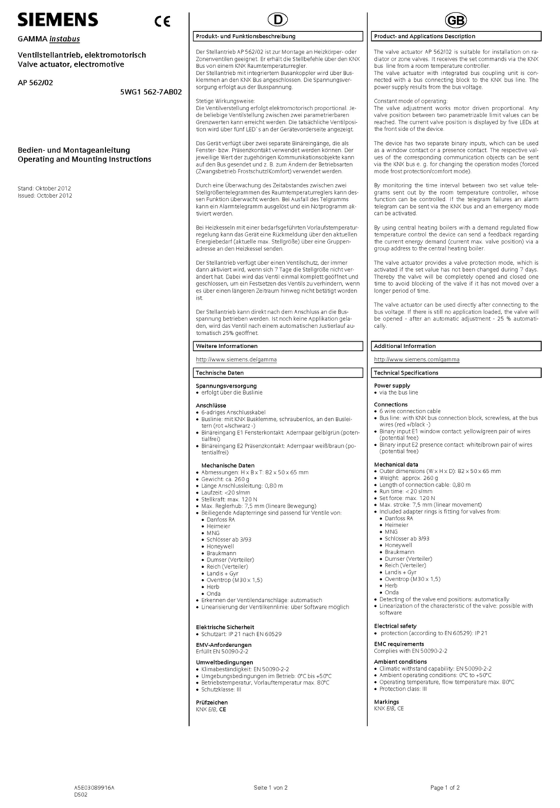
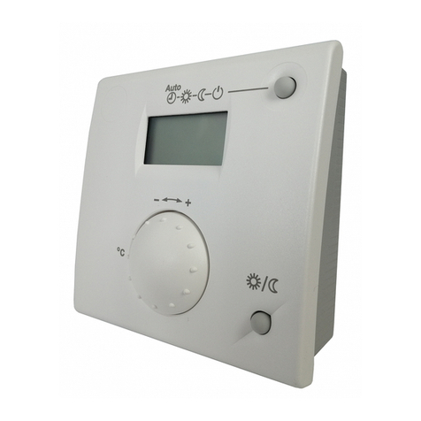
  9. Siemens SSA911.01TH User manual

Siemens SSA911.01TH User manual

A6V11739247_en--_a Smart Infrastructure
2020
-
10
-
08
Smart valve actuator
SSA911.01TH
Wireless radiator valve actuator, works with RDS110.R
● RF-controlled actuator communication based on THREAD protocol (2.4 GHz,
bidirectional)
● Connection and operation with RDS110.R and optionally RCR114.1
● Battery-powered by commercially available 1.5 V AA batteries
● Valve thread connection M30x1.5 mm
● Nominal stroke 2.5 mm
● Valve positioning force 90 N
● Automatic adaptation to valve
● Integrated temperature sensor and PI controller
2
Siemens A6V11739247_en--_a
Smart Infrastructure 2020-10-08
Use
● The SSA911.01TH wireless radiator valve actuator is designed to work on radiator
valves of different manufacturers in HVAC applications using M30x1.5 thread. It operates
the valve to control the water flow and controls the room temperature.
● The valve actuator works only in combination with Siemens Smart Thermostat
RDS110.R and optionally with wireless repeater RCR114.1.
● One RDS110.R can be paired with up to 6 radiator valve actuators in parallel. Up to 3
wireless repeaters RCR114.1 can be used to extend the range of the network.
Smart Thermostat
RDS (Application)
RDS110.R SSA911.01TH RCR114.1
RDS110.R
RCR114.1
SSA911.01TH
Topology with RDS110.R Topology with RCR114.1
3
Siemens A6V11739247_en--_a
Smart Infrastructure 2020-10-08
Functions
Function Description
Communication The communication protocol used is THREAD.
THREAD is a low-power wireless mesh networking protocol and enables device-to-device
and device-to-cloud communication. THREAD is based on IEEE 802.15.4 radio standard.
Parallel operation Up to 6 actuators can be paired and operated with 1 RDS110.R or RCR114.1
Pairing The pairing process must be started on the Smart Thermostat and via HMI on the
SSA911.01TH
Calibration At first start-up, the SSA911.01TH automatically detects the end positions of the radiator
valve and calculates the available stroke. The actuator uses this information for positioning
between 0 and 100 %
Displaying status
information
Actuator status information is indicated on the display
● Setpoint temperature
● Connection to Smart Thermostat
● Radio signal strength
● Battery status (only active when the battery is low)
● Error codes
Connection test When this function is activated, the actuator sends a signal to the connected Smart
Thermostat. Information about the actuator will be shown on the display of the Smart
Thermostat.
Reset and start
new pairing
The current connection to RDS110.R or RCR114.1 is deleted. A new pairing process to
connect to another Smart Thermostat device starts automatically.
Adaptation to
valve
This function starts a new calibration of the SSA911.01TH to the attached valve.
Factory reset Reset the actuator to factory settings. Any existing connection to RDS110.R or RCR114.1 is
deleted and the stem is retracted.
Firmware version Shows the running version of the firmware.
Back up mode In case of a loss of communication, the internal PI-controller controls the temperature
according to the last setpoint received from the Smart Thermostat using the internal
temperature sensor.
Low batteries When the battery capacity drops to 20 %, the actuator displays the battery symbol as a pre-
warning.
A command is sent to the Smart Thermostat and a low battery indication is shown on the
RDS110.R.
Once the batteries are empty, the actuator sends a signal to the Smart Thermostat controller
and shuts down operation with a minimum valve position of 15 %.
Error codes In case of an actuator malfunction or communication error with the Smart Thermostat, an
error code is shown on the display of the SSA911.01TH. See Error codes [➙ 9]
Type summary
Type Stock no. Description
SSA911.01TH S55181-A101 Smart radiator valve actuator
Scope of delivery
Every SSA911.01TH is supplied with 2 inserted AA alkaline batteries (LR6) and a Quick
guide (A5W00046617).
4
Siemens A6V11739247_en--_a
Smart Infrastructure 2020-10-08
Accessories
Adapter AV.. for third-party valves
Type (= stock no.) For radiator valves from:
AV51 Beulco distributor M30x1.0
AV52 Comap
AV53 Danfoss RA-N (RA2000)
AV54 Danfoss RAVL
AV56 Giacomini
Theft protection kit
Type Stock no.
ATN5 S55845-Z244
The theft protection kit secures the actuator; it prevents the batteries from being removed
and the actuator from being unscrewed from the radiator valve without the use of a tool.
Equipment combination
s
Siemens valves
The SSA911.01TH is suited for use with the following types of Siemens radiator valves:
Type kVS
[m3/h]
PN Data sheet
VDN1.., VEN1..
Radiator valves 0.25…1.41
10
CE1N2105
VDN2.., VEN2.., VUN2.. CE1N2106
VD1..CLC.. 1.9…2.6 CE1N2103
VPD.., VPE.. MCV radiator valves 0.02…0.48 CE1N2185
VD1.., VE1.. * Radiator valves 0.25…3.4 CE1N2145,
VD2.., VE2.., VU2.. * CE1N2146
For radiator valves with AV.. adapters, see Accessories [➙ 4]
kVS = Nominal flow rate of chilled water (5…30 °C) through the fully opened valve (H100) at a differential
pressure of 100 kPa (1 bar)
* No longer available
5
Siemens A6V11739247_en--_a
Smart Infrastructure 2020-10-08
Third-party valves without adapter
The SSA911.01TH can operate third-party radiator valves without adapter, provided they
have a M30x1.5 mm connecting thread and meet the following requirements:
Force 90 N nominal
Fully closed x > 9.0 mm
Fully open y ≤ 14.5 mm
Valves of the following manufacturers may be used with the SSA911.01TH:
● Honeywell MNG
● Cazzania
● Heimeier
●
TA
● Finimetall
● Oventop M30x1.5 (from 2001 onward)
● Junkers
●
Danfoss
Valve pre-adjustment / kV-limitation
For valve pre-adjustments, refer to the relevant technical documentation on the valves.
Ensure a minimum valve stroke of > 0.5 mm.
Product documentation
Title Contents Document ID
Smart valve actuator
SSA911.01TH
Data sheet: product description A6V11739247
Quick guide Smart Valve
Actuator SSA911.01TH
Instructions for mounting, commissioning and
operating SSA911.01TH
A5W00046617
Mounting instructions Smart
Thermostat RDS110.R
Instructions for mounting RDS110.R A5W90008181
Quick guide Smart Thermostat
RDS110.R
Instructions for commissioning and operating
RDS110.R
A5W90008183
Smart Thermostat Wireless
RDS110.R
Data sheet: product description A6V11562461
RDS110.R Smart Thermostat
Wireless – User Guide
Detailed information on RDS110.R, including
installation, commissioning and operation
A6V11562455
Mounting instructions Smart
Thermostat Receiver RCR114.1
Instructions for mounting RCR114.1 A5W90008182
Quick guide Smart Thermostat
Receiver RCR114.1
Instructions for commissioning and operating
RDS110.R
A5W90008184
Smart Thermostat Receiver
RCR114.1
Data sheet: product description A6V11562464
Related documents such as environmental declarations, CE declarations, etc., can be
downloaded at the following Internet address:
http://siemens.com/bt/download
6
Siemens A6V11739247_en--_a
Smart Infrastructure 2020-10-08
Notes
Security
CAUTION
National safety regulations
Failure to comply with national safety regulations may result in personal injury and property
damage.
●
Observe national provisions and comply with the appropriate safety regulations.
WARNING
Burns from hot surface
The screw nut with which the actuator is fastened on the radiator valve will become hot.
Risk of burns from contact with the screw nut.
When servicing the actuator:
● Switch off the radiator.
●
Allow the radiator to cool off.
WARNING
Explosion due to fire or short circuit, even with discharged batteries
Risk of injury due to flying parts
● Prevent the batteries from coming into contact with water.
● Do not recharge batteries.
● Do not damage or disassemble batteries.
●
Do not beat batteries over 85
°
C.
WARNING
Leakage of electrolyte
Severe burns
● Handle damaged batteries only wearing suitable protective gloves.
● In case of contact with electrolyte, rinse eyes immediately with plenty of water. Consult
a doctor.
Observe the following:
● Observe the polarities (+/-).
● The batteries must be new and undamaged.
● Do not mix new and used batteries.
Store, transport and dispose of the batteries in compliance with local requirements,
regulations and laws. Also observe the instructions of the battery manufacturer.
7
Siemens A6V11739247_en--_a
Smart Infrastructure 2020-10-08
Mounting
The SSA911.01TH is mounted on the radiator valve. There are no preferred mounting
positions; the actuator SSA911.01TH may be operated in all mounting positions. Make sure
the display is visible and the button is accessible.
WARNING
Falling objects
Overhead installation may result in injury from falling objects.
●
Do not install the actuator more than 2
m above ground.
Firmly tighten the screw nut by hand. No tools are required to tighten the actuator on the
valve.
Commissioning
w Install and commission the RDS110.R and (optionally) the RCR114.1
w Choose the “Radiator valve” application on the Smart Thermostat (for documentation,
see Product documentation [➙ 5])
w Start the installation and commissioning of the SSA911.01TH (see also Quick guide
A5W00046617)
1. Mechanical mounting of the SSA911.01TH on the radiator valve
– Tighten the threaded screw nut firmly by hand (do not use tools)
2. Remove plastic slip securing the batteries from the SSA911.01TH and wait for the
actuator to start up (approximately 5 s)
3. Press the button on the SSA911.01TH for automatic calibration process (> 2 s) and wait
for the confirmation of the calibration on the display
4. Start the pairing process on the RDS110.R in the advanced setting menu by pressing
“Pair new devices”
5. Press the button on the SSA911.01TH to start pairing (> 2 s). Pairing to Smart
Thermostat may take up to 30 s.
a Once the SSA911.01TH is paired to the RDS110.R, the display will confirm the
connection and switch off.
a The SSA911.01TH is now controlled by the Smart Thermostat
Unsuccessful pairing or calibration to the valve is indicated by an error code on the display
(see Error codes [➙ 9]).
8
Siemens A6V11739247_en--_a
Smart Infrastructure 2020-10-08
Operation
HMI
The interface consists of an LCD display [1] and one push
button [2].
During normal operation, the display is switched off in order
to conserve energy and ensure a long battery life.
Display Function Description
THREAD Communication Blinks during pairing mode with Smart Thermostat
Valve adaptation Shown during adaptation of the actuator to the radiator valve
Confirmation / acknowledgment Confirms a positive result after any successful operation
Low battery status Shown when status information feature is activated if the battery
is low
Connection test Shown for 30 s while a connection test is performed
The ID of the connected device will be shown on the RDS110.R
display
Key lock Shown when pressing the button if key lock mode is activated
In key lock mode, no manipulation on the actuator is possible.
Error Shown with error code when an error has occurred
Disappears when normal status has been reached again
Factory reset Shown during a factory reset process
Setpoint temperature
Temperature unit
Interactive symbols shown during pairing, adaptation and factory reset functions:
● no: appears after choosing function
– short button press (< 1 s) exits the function, turns the display off and sends the actuator
to sleep mode
– long button press (> 2 s) confirms the chosen function
● yes: appears after confirming the function (except during factory reset)
● Go: indicates the confirmed function is starting
9
Siemens A6V11739247_en--_a
Smart Infrastructure 2020-10-08
Error codes
In case of an actuator malfunction or communication error with the Smart Thermostat, an
error code is shown on the display of the SSA911.01TH.
Error codes cannot be acknowledged on the SSA911.01TH. The error code is shown on the
display for as long as the error is active and will disappear once normal status has been
reached.
Error notifications are also sent to the Smart Thermostat and shown on the Smart
Thermostat display. E53 is at first only shown on SSA911.01TH and not immediately shown
on the Smart Thermostat. It will take some time to appear on the Smart Thermostat.
Code Error Cause Measures
Automatic
adaptation failed
● The actuator did not correctly adapt to the valve
or could not detect the end positions of the valve
● The actuator is not connected to a radiator valve
● Check the valve type and stroke
compatibility with the SSA911.01TH and
repeat the adaptation
● Check the mechanical valve connection,
adjust, and repeat the adaption
● Ensure that the valve is working correctly
and that the valve stem is not stuck and
repeat the adaptation
Mechanical valve
actuator error
● The movement of the actuator was too short to
detect the end positions of the valve
● Motor movement failure
● The actuator is not connected to a radiator valve
● The stroke and/or end positions of the valve are
not compatible with the SSA911.01TH
No controller found
– pairing failed
● No RDS110.R or RCR114.1 is available to
connect
● The Smart Thermostat is out of range
● RF chip failure
● Check and adjust the settings on Smart
Thermostat and re-start the pairing
process
● Decrease the distance between the
SSA911.01TH and the Smart Thermostat
and re-start the pairing process
Connection to
Smart Thermostat
lost
● The current connection to the Smart Thermostat
is not available anymore (RF chip failure)
● The paired RDS110.R or RCR114.1 is not
available anymore (e.g. loss of power)
● The Smart Thermostat is out of range
● Check the power supply and availability
of the Smart Thermostat
● Decrease the distance between the
SSA911.01TH and the Smart Thermostat
No new pairing process is required
to resolve E53. The SSA911.01TH
will automatically re-connect to the
Smart Thermostat once the
network is available again.
10
Siemens A6V11739247_en--_a
Smart Infrastructure 2020-10-08
M
aintenance
The SSA911.01TH is maintenance free.
The actuator and the Smart Thermostat will indicate when replacing the batteries is required
approximately 2 months before the batteries are completely empty and the actuator switches
off.
Replacing the batteries
To replace the batteries, the SSA911.01TH should remain mounted on the radiator valve
and the Smart Thermostat should remain on power and switched on. Replacing the batteries
does not require any tools. For optimal performance, the use of high performance alkaline
batteries is recommended.
1. Remove the batteries
– Open the white battery cover [1]
– Remove the metallic slider [2]
– Take the batteries out [3]
2. Insert new batteries - 2 x LR6 (Alkaline AA) [4]
3. Re-insert the metallic slider [5] and put the white battery cover back on [6]
a The actuator will automatically start a new calibration and after successful calibration will
automatically re-establish the connection to the Smart Thermostat
Unsuccessful pairing or calibration is indicated by an error code on the display (see Error
codes [➙ 9]).
Disposal
The device is considered an electronic device for disposal in accordance
with the European Guidelines and may not be disposed of as domestic
garbage.
● Dispose of the device through channels provided for this purpose.
● Comply with all local and currently applicable laws and regulations.
● Dispose of empty batteries in designated collection points.
11
Siemens A6V11739247_en--_a
Smart Infrastructure 2020-10-08
Warranty
Technical data on specific applications are valid only together with Siemens products listed
under "Equipment combinations". Siemens rejects any and all warranties in the event that
third-party products are used.
Radio
eq
uipment directive
The device is using harmonized frequency in Europe, and is also in compliance with the
Radio Equipment Directive (2014/53/EU, formerly 1999/5/EC).
Open Source Software (OSS)
Software License Summary
These devices incorporate open source software (OSS), please refer to the OSS document
for the specific controller type and valid version set.
Title: Readme OSS “SSA911.01TH – Rev. FS-01”
All open source software components used within the product (including their copyright
holders and the license conditions) can be found in the document A6V11938504 at
http://siemens.com/bt/download.
Cyber security disclaimer
Siemens provides a portfolio of products, solutions, systems and services that includes
security functions that support the secure operation of plants, systems, machines and
networks. In the field of Building Technologies, this includes building automation and control,
fire safety, security management as well as physical security systems.
In order to protect plants, systems, machines and networks against cyber threats, it is
necessary to implement – and continuously maintain – a holistic, state-of-the-art security
concept. Siemens’ portfolio only forms one element of such a concept.
You are responsible for preventing unauthorized access to your plants, systems, machines
and networks which should only be connected to an enterprise network or the internet if and
to the extent such a connection is necessary and only when appropriate security measures
(e.g. firewalls and/or network segmentation) are in place. Additionally, Siemens’ guidance on
appropriate security measures should be taken into account. For additional information,
please contact your Siemens sales representative or visit
https://www.siemens.com/global/en/home/company/topic-areas/future-of-
manufacturing/industrial-security.html.
Siemens’ portfolio undergoes continuous development to make it more secure. Siemens
strongly recommends that updates are applied as soon as they are available and that the
latest versions are used. Use of versions that are no longer supported, and failure to apply
the latest updates may increase your exposure to cyber threats. Siemens strongly
recommends to comply with security advisories on the latest security threats, patches and
other related measures, published, among others, under
https://www.siemens.com/cert/en/cert-security-advisories.htm.
12
Siemens A6V11739247_en--_a
Smart Infrastructure 2020-10-08
Technical data
Power supply
Battery type 2 x alkaline batteries LR6 (AA) 1.5 V
Battery life 2 years
Radio communication
Frequency range 2.4…2.4385 GHz
Max. transmission power 3.5 dBm
Range ≤ 30 m, depending on application and building
Protocol THREAD, 6LoWAN IEEE802.15.4
Actuator
Stroke nominal 2.5 mm
minimal 0.5 mm
Positioning force typically 90 N
Noise level EN ISO 3741
< 30 dBA
Built-in temperature sensor
Sensing element NTC 4.7 kΩ resistor
Measuring range 0…50 °C
Internal controller
Type PI
Degree of protection
Protection class Class III according to IEC 60730-1
Protection degree of housing IP 30 1) according to IEC 60529
Pollution degree Class 2 according to IEC 60730
Environmental conditions
Operation
Temperature -20…54°C
Humidity (non-condensing) 65 % r.h. ± 20 %
Transportation
Temperature -30...45 °C
Humidity 65 % r.h. ± 20 %
Storage
Temperature -30...45 °C
Humidity 65 % r.h. ± 20 %
Medium temperature permissible in connected valve 1…70 °C
Directives and standards
Product standard IEC 60730-x
Electromagnetic compatibility (field of use) For residential, commercial, and industrial environments
EU conformity (CE) A5W00090263A 2)
EAC compliance Eurasian compliance for all SAY..P..
13
Siemens A6V11739247_en--_a
Smart Infrastructure 2020-10-08
Environmental compatibility
Product environmental declarations A6V11952727 2) include data on environmentally friendly product design and
testing (RoHS compliance, material composition, packaging, environmental benefits, disposal).
Materials and Dimensions
Display LCD
Housing material Plastic ASA+PC
color White NCS S 052-G
Thread M30x1.5
W x H x D See Dimensions [➙ 13]
Weight
1) Completely mounted
2) Documents can be downloaded at http://www.siemens.com/bt/download
Dimensions
Dimensions in mm
[kg]
0.305
Revision numbers
Type Valid from rev. no.
SSA911.01TH
S55181-A101
..01
14
Siemens A6V11739247_en--_a
Smart Infrastructure 2020-10-08
Issued by
Siemens Switzerland Ltd
Smart Infrastructure
Global Headquarters
Theilerstrasse 1a
CH-6300 Zug
Tel. +41 58 724 2424
www.siemens.com/buildingtechnologies
©
Siemens Switzerland Ltd, 20
20
Technical specifications and availability subject to change without notice.
Document ID A6V11739247_en--_a
Edition 2020-10-08

Other manuals for SSA911.01TH

2

Other Siemens Controllers manuals

Siemens RWF50.3 User manual

Siemens

Siemens RWF50.3 User manual

Siemens RC 195 User manual

Siemens

Siemens RC 195 User manual

Siemens MT Series Owner's manual

Siemens

Siemens MT Series Owner's manual

Siemens sinamics dcp User manual

Siemens

Siemens sinamics dcp User manual

Siemens SFP21/18 User manual

Siemens

Siemens SFP21/18 User manual

Siemens SIMOTION D410 Quick start guide

Siemens

Siemens SIMOTION D410 Quick start guide

Siemens RUGGEDCOM WIN5123 User manual

Siemens

Siemens RUGGEDCOM WIN5123 User manual

Siemens Simatic S7-300 User manual

Siemens

Siemens Simatic S7-300 User manual
Siemens SIMATIC ET 200SP User manual

Siemens

Siemens SIMATIC ET 200SP User manual

Siemens SINAMICS S120 Technical Document

Siemens

Siemens SINAMICS S120 Technical Document

Siemens Simatic S7-300 User manual

Siemens

Siemens Simatic S7-300 User manual

Siemens SIMATIC S7-1200 User manual

Siemens

Siemens SIMATIC S7-1200 User manual

Siemens Acvatix G B111.9E/MO Series User manual

Siemens

Siemens Acvatix G B111.9E/MO Series User manual

Siemens GXD 31.1 Series User manual

Siemens

Siemens GXD 31.1 Series User manual

Siemens SIMATIC S5-95F User manual

Siemens

Siemens SIMATIC S5-95F User manual

Siemens Reyrolle 7SR45 User manual

Siemens

Siemens Reyrolle 7SR45 User manual

Siemens OpenAir GDE131.1U User manual

Siemens

Siemens OpenAir GDE131.1U User manual

Siemens SINUMERIK 808D User manual

Siemens

Siemens SINUMERIK 808D User manual

Siemens Flowrite 599 Series User manual
Siemens

Siemens Flowrite 599 Series User manual

Siemens SIRIUS 3RW30 User manual

Siemens

Siemens SIRIUS 3RW30 User manual

Siemens SIMATIC NET User guide

Siemens

Siemens SIMATIC NET User guide

Siemens SIMATIC S7 User guide

Siemens

Siemens SIMATIC S7 User guide

Siemens RWF40.000A97 User manual

Siemens

Siemens RWF40.000A97 User manual

Siemens Synco 700 Series Operator's manual

Siemens

Siemens Synco 700 Series Operator's manual

Popular Controllers manuals by other brands

Craftmade WUCI-1000 Installation and operating instructions

Craftmade

Craftmade WUCI-1000 Installation and operating instructions
Thorlux SmartTouch installation instructions

Thorlux

Thorlux SmartTouch installation instructions

Lawn Genie L80306P Installation and operation guide

Lawn Genie

Lawn Genie L80306P Installation and operation guide

Varian Turbo-V 150 PCB instruction manual

Varian

Varian Turbo-V 150 PCB instruction manual

Tornado Genesis Super Trucks user manual

Tornado

Tornado Genesis Super Trucks user manual

Samson TROVIS 5431 Mounting and operating instructions

Samson

Samson TROVIS 5431 Mounting and operating instructions

Coleman 68012 user manual

Coleman

Coleman 68012 user manual

ABB ACS580-01 drives Quick installation and setup guide

ABB

ABB ACS580-01 drives Quick installation and setup guide

EOS Infratec Classic Assembly and operating instruction

EOS

EOS Infratec Classic Assembly and operating instruction

Emerson Fisher 92S instruction manual

Emerson

Emerson Fisher 92S instruction manual

LEDBOX LD1050692 user manual

LEDBOX

LEDBOX LD1050692 user manual

RMT DX5100 Technical manual

RMT

RMT DX5100 Technical manual

HomeMatic HM-LC-Dim1T-Pl operating manual

HomeMatic

HomeMatic HM-LC-Dim1T-Pl operating manual

Evco EV9376 manual

Evco

Evco EV9376 manual

Dragino LT Series user manual

Dragino

Dragino LT Series user manual

Klinkmann Unitronics Vision V230 BATTERY REPLACEMENT INSTRUCTIONS

Klinkmann

Klinkmann Unitronics Vision V230 BATTERY REPLACEMENT INSTRUCTIONS

Microchip Technology dsPIC30F introduction

Microchip Technology

Microchip Technology dsPIC30F introduction

Fox SHUTTER Wi-STR1S2-P manual

Fox

Fox SHUTTER Wi-STR1S2-P manual

manuals.online logo
manuals.online logoBrands
  • About & Mission
  • Contact us
  • Privacy Policy
  • Terms and Conditions

Copyright 2025 Manuals.Online. All Rights Reserved.