manuals.online logo
Brands
  1. Home
  2. •
  3. Brands
  4. •
  5. Siemens
  6. •
  7. Controllers
  8. •
  9. Siemens SIRIUS 3SX5100-2F User manual

Siemens SIRIUS 3SX5100-2F User manual

GWA 4NEB 334 8684-10 DS 01 Technische Änderungen vorbehalten. Zum späteren Gebrauch aufbewahren. Last update: 10 Februar 2011
Bestell-Nr. / Order No.: 3ZX1012-0SX51-2FA1 Subject to change without prior notice. Store for use at a later date. © Siemens AG 2011
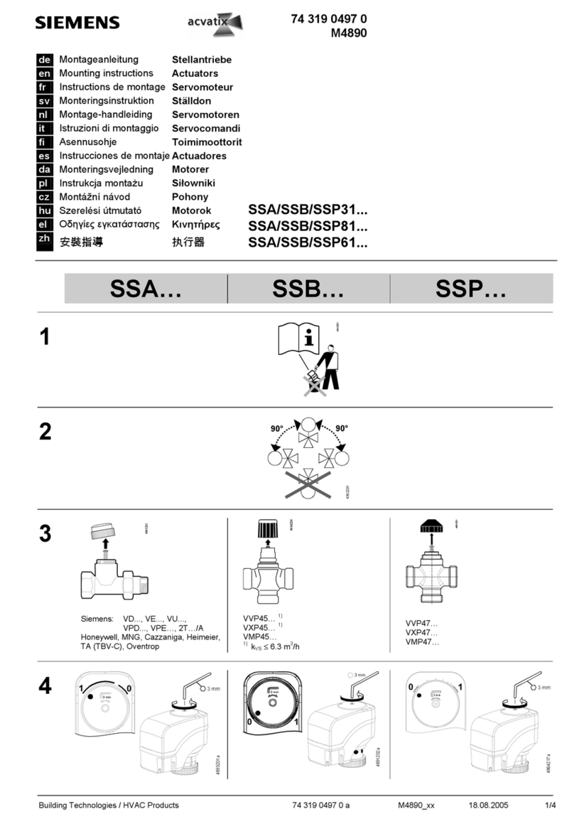
Antriebskopf getrennter Betätiger mit Zuhaltung
Actuator head, separate actuator with tumbler
Tête de commande avec détrompeur séparé, à maintien
Cabeza de accto., actuador separado con retención
Testina di comando azionatore sep. con blocco di ritenuta
Atuador separado da cabeça de acionam. com retenção
Ayrıkilitli aktuatör tahrik başlığı
Приводная головка разделенных актуаторов сблокировкой
带锁止装置的分开式执行器的驱动头
Wechsel des Antriebskopfes
1.
2. Betätiger darf während des Umbaues nicht im Antriebskopf verbleiben.
3. Lösen der 4 Deckelschrauben und Demontage des Gehäusedeckels (gelb).
4.
5. Lösen des Antriebskopfes durch Drehen des Verriegelungsbleches (A) nach
rechts.
6. Sichtkontrolle: Den offen liegenden Stößel sowie den Betätiger auf
Verschleiß, Bruch und andere Defekte kontrollieren.
7. Aufsetzen und vollständiges Herunterdrücken des neuen Antriebkopfes.
8. Verriegelung des Antriebskopfes durch Drehen des Veriegelungshebels (A)
nach links Vorgehensweise wie unter Punkt 5 beschrieben.
9. Kontrolle:
a) Richtige Einbaulage des Antriebskopfes.
b) Sichtkontrolle nach offensichtlich defekten und losen Teilen.
10. Einbringen des neuen Füllstückes (B) bis Anschlag.
11. Montage des Gehäusedeckels, Anzugsdrehmoment der Schrauben
mit 0,8 Nm.
12. Funktionskontrolle des gesamten Schalters gleich der Erstinbetriebnahme,
Anlegen der Spannung, Prüfung der Verriegelung.
Changing the actuator head
1.
2. The actuator must not stay in the actuator head during replacement.
3. Remove the 4 cover screws and dismantle the enclosure cover (yellow).
4.
5. Remove the actuator head by turning the locking plate (A) to the right.
6. Visual inspection: Check the exposed plunger and the actuator for any wear,
breakage or other defects.
7. Place the new actuator head into position and press it down completely.
8. Lock the actuator head by turning the locking plate (A) to the left – same
procedure as described under point 5
9. Check:
a) Mounting position of the actuator head
b) Visual inspection for any obviously defective and loose parts.
10. Insert the new filler (B) as far as it will go.
11. Mount the enclosure cover, tightening the screws with a torque of 0.8 Nm.
12. Carry out a functional check of the entire switch as soon as it is put into
operation for the first time, apply the voltage, and check the interlock.
Remplacement de la tête de commande
1.
2. Le détrompeur doit être sorti de la tête de commande pour le remplacement.
3. Déserrer les 4 vis du couvercle et déposer ce dernier (jaune).
4.
5. Détacher la tête de commande en tournant la tôle de verrouillage (a) vers la
droite.
6. Contrôle visuel : contrôler l’état du poussoir et du détrompeur (usure,
cassures, etc.).
7. Mettre la nouvelle tête de commande en place et l’enfoncer à fond.
8. Verrouiller la tête de commande en tournant la tôle de verrouillage (A) vers la
gauche - voir point 5
9. Contrôle :
a) positionnement de la tête de commande,
b) contrôle visuel de pièces détériorées ou ayant du jeu.
10. Introduire la pièce d’obturation (B) jusqu’en butée.
11. Fixer le couvecle, couple de serrage des vis 0,8 Nm.
12. Contrôle fonctionnel de l’interrupteur de position complet comme lors de la
première mise en service, mise sous tension, contrôle du détrompage.
Reemplazo de la cabeza de accionamiento
1.
2. El actuador no debe permancer dentro de la cabeza de accionamiento
durante las operaciones de transformación.
3. Desenroscar los 4 tornillos de la tapa y desmontar ésta ( el la pieza
amarilla).
4.
5. Soltar la cabeza de accionamiento girando hacia la derecha la chapa de
bloqueo (A).
6. Control visual: Comprobar el vástago ahora visible y el actuador para
detectar posibles desgastes, roturas u otros defectos.
7. Colocar la nueva cabeza de accionamiento y empujarla completamente
hacia dentro
8. Bloquear la cabeza de accionamiento girando hacia la izquierda la chapa de
bloqueo (A), proceder como se indica en el punto 5
3SX5100-2F
SIRIUS
s
A
B
Deutsch
GEFAHR
Achtung
Vorsichtiges Herausnehmen des Füllstückes (B) mit geeignetem
Werkzeug ohne Beschädigung am Gehäuse, nicht verwechseln mit dem
Fixierstück, welches dahinter sitzt.
English
DANGER
Notice
Carefully take out the filler (B) using a suitable tool without damaging the
enclosure. Do not confuse it with the fixing piece that is located behind it.
!
!
Français
DANGER
Important
Extraire la pièce d’obturation (B) avec précaution en utilisant un outil
approprié et en veillant à ne pas endommager le boitier ; ne pas
confondre la pièce d’obrturation avec la pièce de fixation positionnée
derrière.
Español
PELIGRO
Atención
Sacar con cuidado la pieza de relleno (B) usando una herramienta
adecuada y sin dañar la caja, y soin confundirla con la pieza de fijación
que está detrás de ella.
!
!
DE A) Verriegelungsblech
B) Füllstück PT A) Chapa de bloqueio
B) Peça de enchimento
EN A) Locking plate
B) Filler TR A) Kilitleme sacı
B) Dolgu parçası
FR A) Tôle de verrouillage
B) Pièce d’obturation РУ A) пластина блокировки
B) проставка
ES A) Chapa de bloqueo
B) Pieza de relleno 中
文
锁板
垫片
IT A) Piastrina di blocco
B) Pezzo di riempimento
Gefährliche Spannung.
Lebensgefahr oder schwere Verletzungsgefahr.
Vor Beginn der Arbeiten Anlage und Gerät
spannungsfrei schalten.
Hazardous voltage.
Will cause death or serious injury.
Disconnect power before working on equipment.
Tension dangereuse.
Danger de mort ou risque de blessures graves.
Mettre hors tension avant d’intervenir sur l’appareil.
Tensión peligrosa.
Puede causar la muerte o lesiones graves.
Desconectar la alimentación eléctrica antes de trabajar
en el equipo.
2/2 Bestell-Nr. / Order No.: 3ZX1012-0SX51-2FA1
9. Control:
a) Posición de la cabeza de accionamiento una vez montada.
b) Control visual para detectar defectos o piezas sueltas.
10. Colocar la nueva pieza de relleno (B) empujándla hasta el tope.
11. Montaje de la tapa de la caja; par de apriete de los tornillo: 0,8 Nm.
12. Contro funcional de todo el interruptor inmediatenete después de su 1ª
puesta en marcha; aplicar la tsnsión, comprobar el bloqueo.
Sostituzione della testina di azionamento
1.
2. Durante il cambio l’azionatore deve essere tolto dalla testina di azionamento.
3. Svitare le 4 viti del coperchio e smontare il coperchio della custodia (giallo).
4.
5. Allentare la testina di azionamento ruotando la piastrina di blocco (A) verso
destra.
6. Controllo visivo: controllare che il pulsante e l’azionatore non presentino
tracce di usura, fratture o altri difetti.
7. Collocare la nuova testina di azionamento in sede e premerla a fondo
8. Serrare la testina di azionamento ruotando la piastrina di blocco (A) verso
sinistra - Procedere come descritto al punto 5.
9. Controllo:
a) Posizionamento della testina di azionamento.
b) Controllo visivo di difetti evidenti e di pezzi allentati.
10. Inserire il nuovo pezzo di riempimento (B) fino alla battuta di arresto.
11. Montare il coperchio della custodia, coppia di serraggio delle viti 0,8 Nm.
12. Controllo funzionale dell’intero interruttore di posizione alla prima messa in
servizio, messa sotto tensione, verifica del bloccaggio.
Substituição da cabeça de acionamento
1.
2. O atuador não pode permanecer na cabeça de acionamento durante a
renovação.
3. Desapertar os 4 parafusos da tampa e desmontar a tampa da caixa
(amarela).
4.
5. Soltar a cabeça de acionamento, rodando a chapa de bloqueio (A) para a
direita.
6. Verificação visual: Verificar a haste exposta e o atuador quanto ao desgaste,
quebra e outros defeitos.
7. Colocar e pressionar completamente para baixo a nova cabeça de
acionamento
8. Bloquear a cabeça de acionamento, rodando a alavanca de bloqueio (A)
para a esquerda – modo de procedimento descrito no ponto 5
9. Verificar:
a) Posição de montagem da cabeça de acionamento.
b) Verificação visual quanto a defeitos visíveis e peças soltas.
10. Colocar a nova peça de enchimento (B) até o encosto.
11. Montar a tampa da caixa, o torque de aperto dos parafusos com 0,8 Nm.
12. Efetuar uma verificação do funcionamento de todo o interruptor no
momento da primeira colocação em funcionamento, aplicação da tensão,
verificação do bloqueio.
Tahrik başlığının değiştirilmesi
1.
2. Aktüat tadilat işlemi sırasında tahrik başlığının içinde kalamaz.
3. 4 adet kapak cıvatasınıgevşetin ve kapağı(sarı) demonte edin
4.
5. Kilitleme sacını(A) sağa döndürerek tahrik başlığınıgevşetin.
6. Görsel kontrol: Açıktaki iticide ve aktüatörde aşınma, kırılma ve başka
arızaların olup olmadığınıkontrol edin.
7. Yeni tahrik başlığınıoturtun ve tam olarak aşağıya bastırın
8. Kilitleme kolunu (A) sola döndürerek tahrik başlığınıkilitleyin – Madde 5'te
açıklandığışekilde hareket edin
9. Kontrol:
a) Tahrik başlığının montaj pozisyonu.
b) Bariz arızalara ve boşta olan parçalara yönelik görsel kontrol.
10. Yeni dolgu parçasını(B) dayanağa yanaşıncaya kadar yerleştirin.
11. Gövde kapağının montajı, cıvataların 0,8 Nm sıkma torku ile sıkılması.
12. İlk çalıştırmada tüm şalterin fonksiyonunu kontrol edin, gerilimi verin,
kilitlemeyi kontrol edin.
Смена приводной головки
1.
2. При ремонте актуатор не должен оставаться вприводной головке.
3. Отворачивание 4 винтов крышки иснятие крышки корпуса (желтый).
4.
5. Снятие приводной головки споворачиванием пластины блокировки (А)
вправо.
6. Визуальный контроль: проверка открыто лежащего толкателя иактуа-
тора на износ, излом идругие дефекты.
7. Установка иполное прижатие новой приводной головки.
8. Поворот рычага блокировки (A) влево иблокировка приводной
головки – последовательность действий как описано впункте
9. Контроль:
a) монтажного положения приводной головки;
b) визуальный контроль на наличие очевидно неисправных и
несмонтрованных частей.
10. Установка новой проставки (B) до упора.
11. Монтаж крышки корпуса, момент затяжки винтов – 0,8 Нм.
12. Контроль работоспособности переключателя сразу после первого
ввода вэксплуатацию, подключения напряжения ипроверки блокировки.
更换驱动头
1.
2. 改造期间,执行器不得留在驱动头内。
3. 松开 4 颗箱盖螺栓并拆卸外壳盖 (黄色)。
4.
5. 通过向右旋转锁板 (A) 来松开驱动头。
6. 目测检查:检查处于打开状态的顶杆和执行器是否磨损、断裂或
有其它损坏。
7. 装上新的驱动头并完全向下按压。
8. 通过向左旋转锁板 (A) 来锁闭驱动头 – 操作步骤参见第 5 节中的
说明。
9. 检查:
a) 驱动头的安装位置。
b) 目测检查部件是否存在明显故障或松动。
10. 将新垫片 (B) 插到底。
11. 安装外壳盖,螺栓的拧紧力矩为 0.8 Nm。
12. 整个开关的功能检查,参考首次调试、电压接通、联锁装置的
检查。
Italiano
PERICOLO
Attenzione
Estrarre con cautela il pezzo di riempimento (B) con un utensile adatto
senza danneggiare la custodia, non confonderlo con il pezzo di fissaggio
posizionato dietro.
Portugûes
PERIGO
ATENÇÃO
Proceder com prudência ao extrair a peça de enchimento (B), utilizar
uma ferramenta adequada e não provocar danos na caixa, não confundir
com a peça de fixação, situada atrás.
!
!
Türkçe
TELiKE
DİKKAT
Dolgu parçasını(B) uygun bir aletle ve gövdeye zarar vermeden çıkarın.
Dolgu parçası, arkasında bulunan sabitleme parçasıile karıştırılmamalı-
dır.
Русский
ОПАСНО
ВНИМАНИЕ!
Проставку (B) снимать аккуратно, сиспользованием соответствую-
щего инструмента, не повреждая корпус, не перепутать сфиксато-
ром, установленным сзади.
!
!
中文
危险
注意
小心取出垫片 (B),使用适当的工具,不要损坏外壳,不要与
后方的定位件混淆。
Technical Assistance:
SIEMENS AG, Technical Assistance
Würzburger Str. 121, D – 90766 Fürth
Tel: +49(0)911-895-5900 (8°° - 17°° CET); Fax: +49(0)911-895 -5907
E-mail: [email protected]
Internet: www.siemens.com/industrial-controls/technical-assistance
!
Tensione pericolosa.
Può provocare morte o lesioni gravi.
Scollegare l’alimentazione prima di eseguire interventi
sull'apparecchiatura.
Tensão perigosa.
Perigo de morte ou ferimentos graves.
Desligue a corrente antes de trabalhar no equipamento.
Tehlikeli gerilim.
Ölüm tehlikesi veya ağır yaralanma tehlikesi.
Çalışmalara başlamadan önce, sistemin ve cihazın
gerilim beslemesini kapatınız.
Опасное напряжение.
Опасность для жизни или возможность тяжелых
травм.
Перед началом работ отключить подачу питания к
установке икустройству.
危险电压。
可能导致生命危险或重伤危险。
操作设备时必须确保切断电源。

Other Siemens Controllers manuals

Siemens SIKOSTART 3RW34 Manual

Siemens

Siemens SIKOSTART 3RW34 Manual

Siemens SINUMERIK 802C User manual

Siemens

Siemens SINUMERIK 802C User manual

Siemens SIMATIC S5-90U User guide

Siemens

Siemens SIMATIC S5-90U User guide

Siemens SINAMICS S120 Parts list manual

Siemens

Siemens SINAMICS S120 Parts list manual

Siemens SSA955 User manual

Siemens

Siemens SSA955 User manual

Siemens SKP25 Series Owner's manual

Siemens

Siemens SKP25 Series Owner's manual

Siemens OpenAir G B181.1E/KN Series User manual

Siemens

Siemens OpenAir G B181.1E/KN Series User manual

Siemens Simatic S7-300 User manual

Siemens

Siemens Simatic S7-300 User manual

Siemens SIRIUS 3RW40 User manual

Siemens

Siemens SIRIUS 3RW40 User manual

Siemens SKP Series Owner's manual

Siemens

Siemens SKP Series Owner's manual

Siemens Powermite 599 Series Owner's manual

Siemens

Siemens Powermite 599 Series Owner's manual

Siemens SIRIUS User manual

Siemens

Siemens SIRIUS User manual

Siemens HydroRanger 200 User manual

Siemens

Siemens HydroRanger 200 User manual

Siemens Synco 200 Operator's manual

Siemens

Siemens Synco 200 Operator's manual

Siemens LMV37.4 Series Operator's manual

Siemens

Siemens LMV37.4 Series Operator's manual

Siemens UP 520/31 User manual

Siemens

Siemens UP 520/31 User manual

Siemens 540-103 User manual

Siemens

Siemens 540-103 User manual

Siemens 7SR224 Use and care manual

Siemens

Siemens 7SR224 Use and care manual

Siemens SIRIUS 3RW30 User manual

Siemens

Siemens SIRIUS 3RW30 User manual

Siemens SIMATIC S7-200 User manual

Siemens

Siemens SIMATIC S7-200 User manual

Siemens LME39 Series User manual

Siemens

Siemens LME39 Series User manual

Siemens MKB-1 User manual

Siemens

Siemens MKB-1 User manual

Siemens RRV851 User manual

Siemens

Siemens RRV851 User manual

Siemens ST950 User manual

Siemens

Siemens ST950 User manual

Popular Controllers manuals by other brands

Tech Controllers EU-F-2z v2 quick guide

Tech Controllers

Tech Controllers EU-F-2z v2 quick guide

Baker Hughes Masoneilan 525 Seris instruction manual

Baker Hughes

Baker Hughes Masoneilan 525 Seris instruction manual

HORNER XLE Firmware update manual

HORNER

HORNER XLE Firmware update manual

Honeywell Stryker VAV operating guide

Honeywell

Honeywell Stryker VAV operating guide

Denon DN-HC4500 - DJ Mixer USB Controller quick start guide

Denon

Denon DN-HC4500 - DJ Mixer USB Controller quick start guide

ABB RHDE8000 operating instructions

ABB

ABB RHDE8000 operating instructions

KMC Controls KMD-5210 Installation and operation guide

KMC Controls

KMC Controls KMD-5210 Installation and operation guide

YGE 150 HV FAI quick start guide

YGE

YGE 150 HV FAI quick start guide

Meridian Analogue Controller 502 user guide

Meridian

Meridian Analogue Controller 502 user guide

Hatteland HD REM SX1-A1 manual

Hatteland

Hatteland HD REM SX1-A1 manual

Vector TRA-F12x-A manual

Vector

Vector TRA-F12x-A manual

Sawo Innova manual

Sawo

Sawo Innova manual

Performance Technologies PCI334A Series Hardware manual

Performance Technologies

Performance Technologies PCI334A Series Hardware manual

GE ACT17CWA Installation and operation manual

GE

GE ACT17CWA Installation and operation manual

PEELLE 2745 Installation and operation manual

PEELLE

PEELLE 2745 Installation and operation manual

Parker iqan-mc3 user manual

Parker

Parker iqan-mc3 user manual

PVI Industries Love 4C Programming guide

PVI Industries

PVI Industries Love 4C Programming guide

Nederman SER.537 instruction manual

Nederman

Nederman SER.537 instruction manual

manuals.online logo
manuals.online logoBrands
  • About & Mission
  • Contact us
  • Privacy Policy
  • Terms and Conditions

Copyright 2025 Manuals.Online. All Rights Reserved.