Installation:
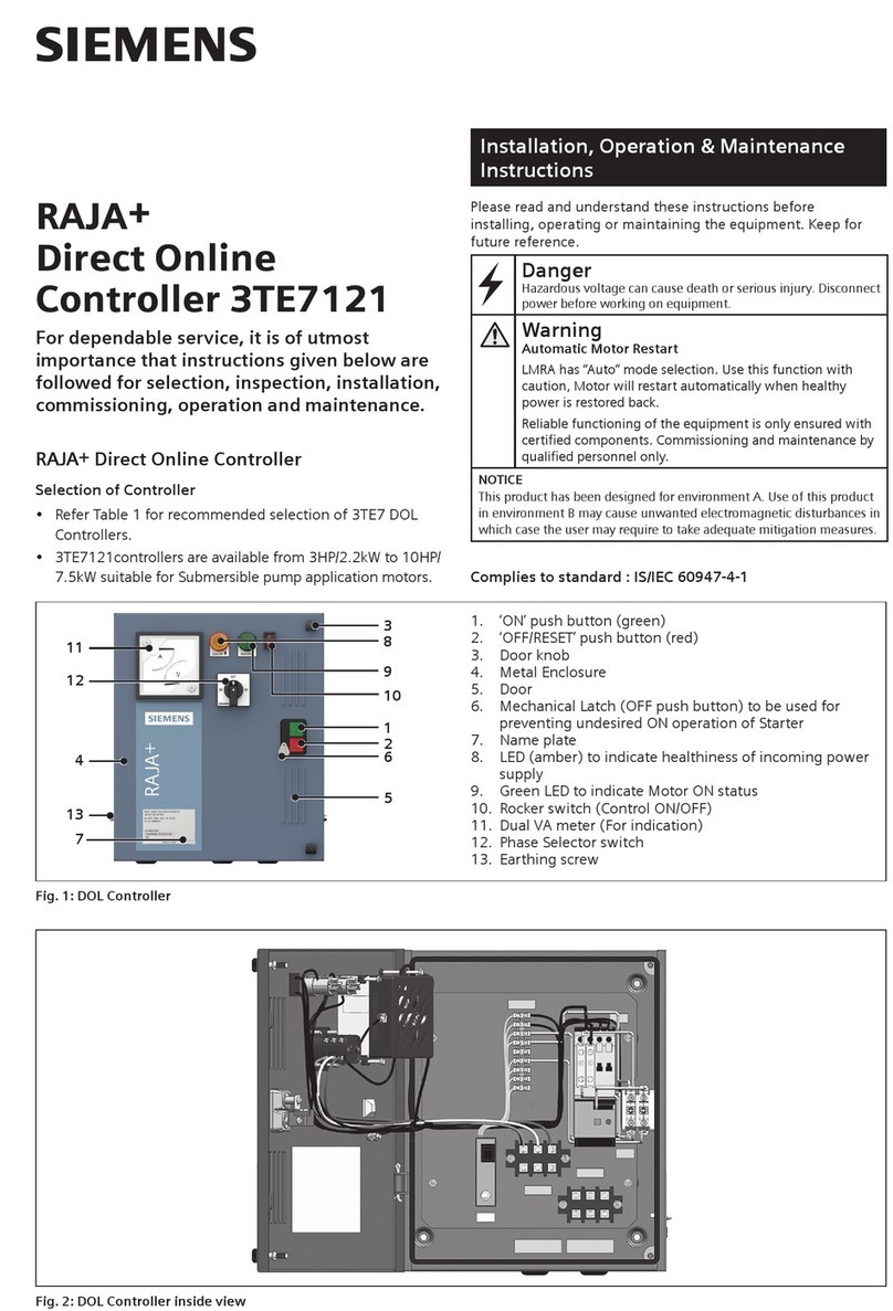
• Openthedoorbyunscrewingthedoorknob.
• Mountthecontrolleronaverticalwall/platefreefrom
vibrationswithpropernutsandbolts.ReferFig.5for
mountingdimensions.
• Removetherubbergrommetsfortheincomingand
outgoingcableconnections.(ReferFig.2).
• Connectincomingandoutgoingcablesasfollows
(ReferFig.2):
– Usepropercableglandstoensuredustproong.For
conduitentryusepackedwashers.
– SelectcorrectsizeofcablesfromTable1.
– Removeapprox.lengthofinsulationasperfollowing
table:
Lengthofinsulation
removal(mm)
Cucablesize
(mm2)
62.5
5 1.5
– Connectlineandmotorcablesexactlyasperwiring
diagrampastedinsidethecoverofthestarter.
– Terminatetheincomingsupplycablesonterminal
blockTB1&outgoingcablestomotoronterminal
blockTB2(Tighteningtorque-Refertable2).
NOTE:LMRAissetinManualmode(Factorysetting)
WLCissetinDeliverymode(Factorysetting)
• Settheoverloadrelayscale(Fig.2)usingproperscrew
driverasfollows:
– Settheoverloadrelaytoratedcurrentmentionedon
motornameplate.
– PressgreenbuttonofthecontactblockCB1(Fig.2)
tostartthemotorandwaittillitreachestonormal
speed.Reducetheoverloadrelaysettingstillittrips.
– Settheoverloadrelayatslightlyhighervalue.
– Allowaresettimeappr.4min.andresettheoverload
relaymanually.
– Restartthemotor.Iftherelaydoesnottrip,consider
theoverloadrelayasproperlyset.
Ifittrips,setitatlittlehighervalueandrecheck.
– Presstheredknob(Fig.2)ontheoverloadrelayto
stopthemotor.
– Closethedoorbyscrewingthedoorknob.
Procedure for connecting WLC sensors & terminations:
• ThesesensorsneedtoberoutedfromleftsideofBase
platethroughcablegland(Pleaseensureduecareto
avoiddamagetothesensors.)
Caution:
• During commissioning or maintenance always ensure
that the main supply is disconnected by switching off
the main switch & Rocker switch.
• Iftherelaytripsevenwhensetatratedmotorcurrent
thesuitabilityofthecontroller/relayfortheparticular
applicationshouldbecheckedwiththenearestSiemens
office.
Operation:
• Ensurethedoorislocked.
• RotatetheMechanicalLatchawayfromOFFpushbutton.
• SwitchOntherockerswitchmarked‘I’.
• CheckthestatusofamberLED.WaittillamberLEDis
continuouslyONthenonlyproceed.
• DependinguponSelectorswitchknobpositionforphase
selection,Indicationofincomingpowersupplyvoltage
canbeseenonDualVAmeter.
• Forstartingthemotor,pressGreenpushbuttonmarked
‘I’(Fig.1).
• LinecurrentofRphaseisindicatedbyDualVAmeter.
• MotorisONwhengreenLEDisON.
• ForstoppingthemotorpressRedpushbuttonmarked‘O’
(Fig.1).
• ForLMRAAuto/Bypassmodes,refertroubleshooting
guideA5E50797230A.
• ForWLCDelivery/Suction/Dualtankmodes,refer
troubleshootingguideA5E50797230A.
• ResetOperation
– Iftheoverloadrelaytrips,Resetmanually.(Allowa
resettimeofapprox.4min.)
Maintenance:
• SwitchofftheControllerandPutLatchontheOFFpush
button,(marked‘O’).Disconnect the main supply by
switching the main switch & Rocker Switch Off before
doing any maintenance.
• Keeptheinteriordustfree.
• Re-tightentheterminalscrewsfromtimetotimeasper
speciedtorqueintable2.
• Nomaintenanceisneededforoverloadrelay.Pleasedo
notopentherelay.
• Replacecontactsofthecontactoriftheywereseverely
pittedorwhenonly40%oftheoriginalcontacttips
remains.
• ReplacementofOverloadRelay(ReferFig.3):
1. Selectaproperrelayexactlyaspertheoriginal.
2. Slightlyloosentheoutgoingterminalscrewsofthe
relay.
3. Disconnectthewiresconnectedtotherelayterminals.
4. Slightlyloosentheoutgoingterminalscrewsofthe
contactor.
Mode For Single Tank application
(Delivery or Suction mode)
For Dual Tank application
(Dual tank mode) For by passing WLC
ConnectionProcedure ConnectsensorsP1,P2&
P3toTerminalX1,X2,X3of
TerminalblockTB5
ConnectsensorsP1,P2
&P3toTerminalX1,X2,
X3ofTerminalblockTB5
&sensorsP4,P5&P6to
TerminalX4,X5,X6of
TerminalblockTB5
Removeconnection
betweenX7-X8ofTerminal
blockTB5.
Removeconnectionfrom
X11ofTB5&Connectitto
X12ofTB5.
2
