Siemens 3RK1904-2AB01 User manual

Adressier- und Diagnoseinstrument für AS-i Module
(inkl. erweiterter Spezifikationen V2.1) 3RK1904-2AB01
Betriebsanleitung Bestell-Nr.: 3RK1703-2WB02-1CA1 Deutsch
GWA 4NEB 333 0761-10 DS 01 Last update: 17 July 2006
Bedien-, Anzeigeelemente und Symbole
Vor der Installation, dem Betrieb oder der Wartung des Geräts muss diese Anleitung gelesen und
verstanden werden.
Beachten Sie die Anschlussdarstellungen zur Einzelslave-Adressierung und zur Anlagendiagnose im
Ausklappblatt des Umschlags.
VORSICHT ACHTUNG
Eine sichere Gerätefunktion ist nur mit
zertifizierten Komponenten gewährleistet!
Wenn auf der Anzeige das Zeichen " " erscheint, dann
sollten Sie sobald wie möglich die Batterien wechseln bzw.
die Akkus nachladen. Trennen Sie das Gerät vom AS-i
Bus, bevor Sie es öffnen. Bei einem Wechsel gehen die
gespeicherten Daten verloren.
WARNUNG
Ein Wechsel der Anlagenzustände in einem laufenden Prozess kann Lebensgefahr bedeuten oder
Anlagenteile beschädigen, falls Funktionsstörungen oder Programmfehler auftreten.
Überzeugen Sie sich davon, dass keine gefährlichen Situationen eintreten können, bevor Sie Funktio-
nen wie Data, Parameter u.s.w. ausführen.
!
ADDR
AS I V=
Profile
Data
Parameter
Memory
COM
ADDR
OFF
MEM
+
3RK1904-2AB01
ESC
!
N117
dAtA
4321b
EDIT
1
3
42
5
1
3
2,4, 5
ASI +
ASI –
IR-Adressing
1
2
3
4
5
6
7
8
1 Hauptanzeige
2 Adressfeld: Anzeige belegter Adressen
3 Eingabebestätigung
4 Wert erhöhen
5 Wert verringern
6 Rücksprung / Escape*
7 Drehschalter für Funktionsauswahl
8 Buchse M 12 für Anschluss an AS-i Bus
AS-i Zertifizierung
EU-Konformitätskennzeichnung
C-Tick-Zeichen
*mit ESC statt mit gelangen Sie jeweils zum Ausgangs-
punkt zurück, ohne die gewählte Funktion auszuführen
✔

2 3RK1703-2WB02-1CA1
OFF manuelles Ausschalten-Schalterstellung "OFF" /
automatisches Ausschalten-beliebige Schalterstellung, nicht "OFF":
Ihr Gerät schaltet sich automatisch aus, wenn ca. 10 Minuten lang weder eine Taste
noch der Drehschalter betätigt wurde; Ausnahme: bei Data und Parameter nach ca. 1
Minute. Ihr Gerät wird nach dem automatischen Abschalten durch Betätigen des Dreh-
schalters oder wieder eingeschaltet.
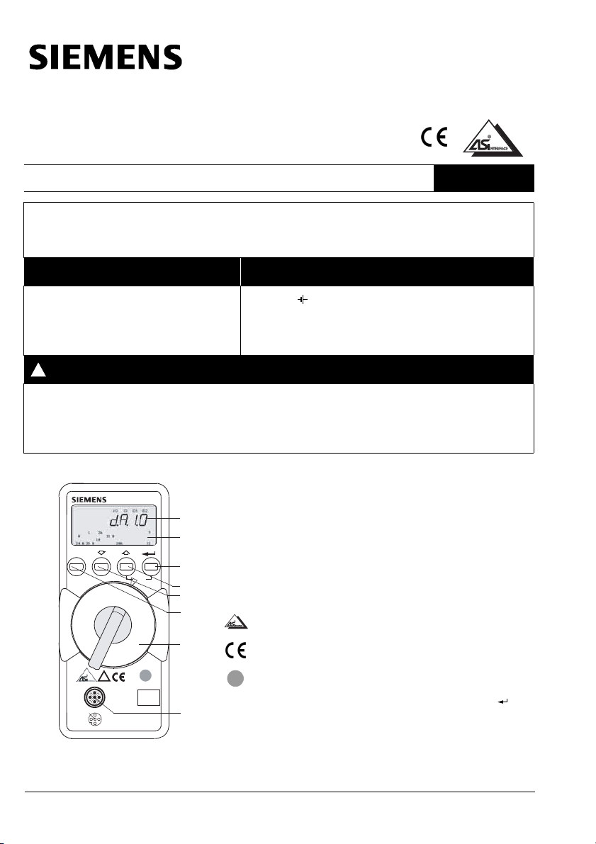
ASI V = Anzeige von AS-i-Spannung und AS-i Stromaufnahme
30.0V: externe AS-i Spannung
0.025 A:Liegt keine externe AS-i Spannung an den Slaves, wird die Stromaufnahme
angezeigt.
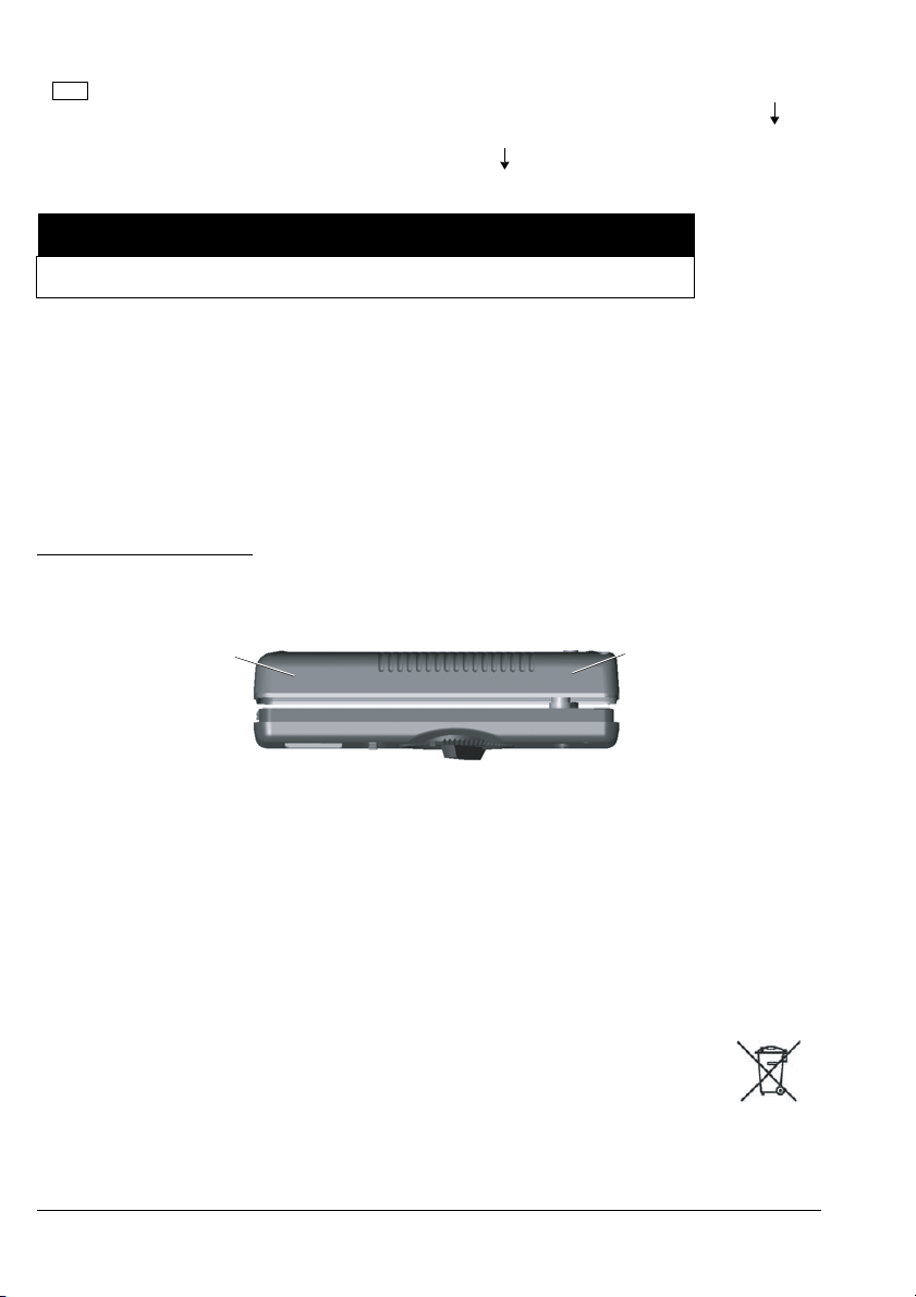
Ausgeschaltete AS-i Netzteile und AS-i Master müssen vom Bus getrennt werden! Bei
Slaves mit höherer Stromaufnahme (z. B. Analogmodule) empfiehlt es sich, ein externes
AS-i Netzteil zu verwenden.
ESC: Wechsel zur Batteriespannungsanzeige und zurück.
ADDR AddrES:Adressieren ohne Speicherung der Buskonfiguration
Hier können Slaves ausgewählt und umadressiert werden.
↵Search:alle Slave-Adressen am Bus suchen
888 alle gefundenen Adressen werden angezeigt
uSEx: eine der gefundenen Adressen wird eingeblendet
USEx: Slave zum Umadressieren auswählen
↵Auswahl bestätigen
(Auswahl entfällt, wenn nur 1 Slave angeschlossen ist)
888 Slave-Adresse blinkt im Adressfeld
setx: die aktuelle Adresse wird eingeblendet
ggf. neue Adresse für aktuellen Slave auswählen
↵neue Adresse wird zum Slave übertragen
ADDR+MEM Addmem: Adressieren mit Speicherung der Buskonfiguration
Funktion wie ADDR, jedoch mit Speicherung neu generierter Adressen im Arbeits-
speicher (Memory 0). Die Speicherung neu vergebener Adressen verhindert Doppel-
adressierungen.
Vor Adressenvergabe für eine neue Anlage sollte der Arbeitsspeicher gelöscht werden.
Arbeitsspeicher löschen:
Betätigen Sie die Tasten und gleichzeitig. clr0 wird eingeblendet und muss mit
bestätigt werden.
Profile profil: Lesen und Schreiben eines Slave-Profils
search: alle Slave-Adressen am Bus suchen
↵eine gefundene Adresse blinkt, das zugehörige Profil wird eingeblendet.
Slave auswählen
ACHTUNG
Falls zwei oder mehr Module mit identischer Slaveadresse am AS-i Bus vorgefunden
werden, zeigt das Gerät dbladd an. Die betreffende Adresse blinkt im Adressfeld.

3RK1703-2WB02-1CA1 3
888 Adresse blinkt, Slave-Profil wird angezeigt
↵Nur bei Slaves nach erweiterter AS-i Spezifikation V2.1 (vierstellige Code-
Anzeige):
EDIT-Ebene anwählen
ggf. neuen Wert für ID1 auswählen
888 Wert für ID1 blinkt in der Hauptanzeige
↵neuen Wert zum Slave übertragen
Data data: Lesen und Schreiben von Slave-Daten-Anzeigemodus
Sie können zwischen zwei Anzeigearten wählen:
direct: Anzeigeder Rohdaten des Slaves
s.h.i.f.t.3: Darstellung im "S7-Modus", zwischen den Zeichen werden Punkte einge-
blendet. Daten vom Slave werden mit 8 multipliziert, Daten zum Slave werden durch 8
dividiert.
Anzeigemodus umschalten
↵EDIT: Einstellmenü aktivieren
Umschalten zwischen direct und S.h.i.F.t.3
↵Auswahl bestätigen
Das "Peripheral Fault Flag" wird durch das blinkende Segment PFF in der Kopfzeile der
Anzeige signalisiert.
Data data: Lesen und Schreiben von Slave-Daten
↵search: alle Slave-Adressen am Bus suchen
Slave auswählen (entfällt bei Adressiersteckeranschluss)
888 4 verschiedene Anzeigen sind möglich:
data / 4321b: Zuordnung der binären Ein- / Ausgänge zur Anzeige
Binäreingänge: 0001b (nur Lesen der Binärwerte)
Binärausgänge: --00b(noout, sofern ohne Ausgang)
nicht vorhandene Ein- / Ausgänge werden mit "—" dargestellt
Eingangsdaten werden laufend aktualisiert
Analogeingänge: Chinp (channel input)
Analogausgänge: noinp (no channel input)
ACHTUNG
Das Slave-Profil dient zur Identifikation von Modultypen. Es besteht aus I / O- und ID-Code. Module
nach erweiterter AS-i Spezifikation V2.1 haben zusätzlich einen ID1- und einen ID2-Code. Der ID1-
Code ist änderbar (siehe Beschreibung des jeweiligen Moduls). Die anderen Codes sind im Modul fest
hinterlegt.

4 3RK1703-2WB02-1CA1
Slave mit Binärausgängen
↵EDIT: Einstellmenü aktivieren
Wert ändern
↵Wert zum Slave übertragen
Slave mit Analogeingängen
↵Auswahl des Slaves bestätigen
Chn: Kanal auswählen
↵Kanal bestätigen und Wert anzeigen, mit ESC zurück
Slave mit Analogausgängen
↵EDIT: Einstellmenü aktivieren
Chn: Kanal auswählen
↵Kanal bestätigen und Wert anzeigen
Wert ändern
↵Wert zum Slave übertragen
Parameter PARA: Lesen und Schreiben der Slave-Parameter im Hex-Format
↵search: alle Slave-Adressen am Bus suchen
die erste belegte Adresse blinkt
Slave auswählen
888 Adresse blinkt, Parameter wird hexadezimal angezeigt.
↵EDIT: Menü zum Lesen und Ändern der Parameter aufrufen.
Slaves mit Parameter-String, z. B. Analog-Slaves
read wird kurz eingeblendet, links steht die Parameter-Nr. und rechts der Wert.
Parameter auswählen
↵Parameter bestätigen
neuen Parameterwert einstellen
888 Hexwert blinkt in der Hauptanzeige
↵Parameter zum Slave übertragen

3RK1703-2WB02-1CA1 5
Slaves ohne Parameter-String, z. B. Digital-Slaves
neuen Parameterwert einstellen
888 Hexwert blinkt in der Hauptanzeige
↵Parameter zum Slave übertragen
Geänderte und zum Slave gesendete Parameter können in der Schalterstellung Memory
mit clr0 gelöscht werden.
888 echoXH: Das empfangene Parameterecho wird hexadezimal angezeigt.
Memory memo: Datensatz laden, speichern, löschen und kopieren
In der Betriebsart "kopieren" können sämtliche Adressen einer gespeicherten Anlage
nacheinander auf einzelne Slaves einer neuen Anlage übertragen werden.
ESC Anzeige freier Speicherplatz in %
↵
Datensatz löschen
888 clear clrx
Inhalt des Arbeitsspeichers Adresse 0 oder der Speicheradresse x = 1, 2, 3 oder 4 bzw.
ALL (0 bis 4) löschen.
Datensatz laden
888 recall rclx
Inhalt der Speicheradresse x = 1, 2, 3 oder 4 in den Arbeitsspeicher Adresse 0 holen.
Datensatz speichern
888 store stox
Arbeitsspeicherinhalt Adresse 0 unter Speicheradresse x = 1, 2, 3 oder 4 ablegen.
Slave-Adressen kopieren
888 copy cpyxready setto clradr oder ESC
cpy : Adressen sämtlicher Slaves von Memory x kopieren. Slave über Adressier-
stecker anschließen. Adresse des angeschlossenen Slaves blinkt, der zu einem Slave
passt.
setto : Übertragung der Adresse starten.
clradr : Slave im Adressfeld löschen. Wurden alle Adressen übertragen, erscheint
die Meldung empty.
ESC: Sollen mehrere Slaves desselben Profils programmiert werden, wird diese
Adresse im Adressfeld nicht gelöscht.
ready: Aufforderung zum Slavewechsel

6 3RK1703-2WB02-1CA1
Abfrage der Firmwareversion
888 3.4:
Drücken Sie bei ausgeschaltetem Gerät (Drehschalter in Stellung OFF) die Taste ,
halten diese gedrückt und drehen Sie gleichzeitig den Drehschalter in die Stellung
"ASI V =". Drücken Sie jetzt dreimal die Taste und halten diese fest. Eine zweistellige
Zahl mit dem Format x.y wird eingeblendet.
Wartung
Batterien austauschen
• Legen Sie das Gerät auf die Frontseite, lösen Sie die beiden Schrauben an der Rückseite und heben
Sie das Gehäuseunterteil, von unten beginnend, ab. An der oberen Stirnseite werden Gehäuseoberteil
und Gehäuseunterteil mit Hilfe von Rasthaken zusammengehalten.
• Nehmen Sie die Batterien aus den Klemmhalterungen, indem Sie diese mit einem Schraubendreher
heraushebeln; setzen Sie den Schraubendreher im Bereich von Bauelementen neben diesen an, ansons-
ten mittig zur Batterie. Setzen Sie 4 neue Batterien entsprechend den angegebenen Polaritätssymbolen
in die Klemmhalterungen ein.
Wichtig beim Zusammenbau: Setzen Sie zunächst das Gehäuseunterteil parallel auf (siehe Bild), drücken
Sie dann die beiden Gehäusehälften zuerst an der unteren (a), anschließend an der oberen (b) Stirnseite
zusammen.
• Befestigen Sie das Unterteil wieder mit den beiden Schrauben.
• Bitte entsorgen Sie die verbrauchten Batterien umweltgerecht!
Wartung Gehäuse
Eine besondere Wartung des Gehäuses ist nicht nötig. Achten Sie auf eine saubere Oberfläche. Verwen-
den Sie zur Reinigung ein leicht feuchtes Tuch. Vermeiden Sie den Einsatz von Putz-, Scheuer- oder
Lösungsmitteln.
Rücknahme und umweltverträgliche Entsorgung
ACHTUNG
COM-Funktionalität der Adressierung wird bei 3RK1904-2AB01 nicht unterstützt.
Bei dem Adressier- und Diagnoseinstrument handelt es sich um ein Produkt der Katego-
rie 9 nach ElektroG (Überwachungs und Kontrollinstrumente). Dieses Gerät fällt nicht
unter die RoHS-Richtlinie.
Nach WEEE 2002 / 96 / EG und ElektroG kennzeichnen wir unsere Elektro- und Elektro-
nikgeräte (ab 8 / 2005) mit dem nebenstehenden Symbol nach DIN EN 50419. Diese
Geräte dürfen nicht mit dem Hausmüll entsorgt werden. Bezüglich der Altgeräte-Rück-
nahme wenden Sie sich bitte an unseren Technical Assistance.
(b) (a)

3RK1703-2WB02-1CA1 7
Technische Kennwerte
Eingangswiderstand bei Spannungsmessung: ca. 300 km
Legende v.M. = vom Messwert, D = Digit
Stromversorgung
Die Standardstromversorgung erfolgt durch 4 Batterien IEC LR6 (NEDA15). Alternativ können auch
Akkus eingesetzt werden.
Zur Batterieschonung erfolgt eine automatische Abschaltung etwa 1 Minute nach der letzten Bedienung.
Elektromagnetische Verträglichkeit EMV
Störaussendung EN 61326 Klasse B
Störfestigkeit EN 61326
Umgebungsbedingungen
Arbeitstemperaturen 0 °C … +50 °C
Lagertemperaturen -20 °C … +75 °C (ohne Batterien)
relative Luftfeuchte max. 75 %, Betauung ist auszuschließen
Höhe über NN bis zu 2000 m
Einsatzort nur in Innenräumen
Mechanischer Aufbau
Abmessungen 84 mm x 195 mm x 35 mm
Gewicht ca. 450 g mit Batterien
Schutzart IP40
Belegung Buchse M 12
Pin 1 ASI +
Pin 3 ASI - / GND
Pin 2 TTL-Out
Pin 4 TTL-In
Pin 5 +5 V
Für die Funktion ohne IR-Adressierung sind nur Pin1 und Pin 3 notwendig (IR ... Infrarot).
Systemmeldungen
Folgende Meldungen müssen mit bestätigt werden, um zur aktuellen Funktion zurückzugelangen.
Messbereich Messgenauigkeit
Spannung 2...35 V ±(3,5 % v.M. + 2 D)
Strom (für Slaves) 0...0,1 A ±(5 % v.M. + 2 D)
ACHTUNG
Um Störungen zu vermeiden, dürfen keine 4 / 5-poligen Adressierkabel
verwendet werden (siehe Ausklappblatt des Umschlags).
1
3
2
4
5

8 3RK1703-2WB02-1CA1
Meldung Funktion Bedeutung
comerr COM Übertragungsfehler
dbladd ADDR Doppeladresse gefunden
echo Parameter Empfangener Parameter XH
empty Memory (copy) Anlage wurde komplett kopiert
error Data, Parameter Adresse 0: Daten und Parameter nicht lesbar
found ADDR Slave-Adressen wurden erkannt
hiload ASI V = Stromlast für Adressiergerät zu groß
lobatt ASI V = Batterie kann volle AS-i Spannung nicht mehr
erzeugen
intern ASI V = Kein AS-i Netzteil am Bus
master ADDR, Profile, Data, Parame-
ter, Memory
aktiver Master am Bus
noasi ADDR Keine Slave-Adresse gefunden
noout Data Der Slavetyp hat keine Ausgänge (no OUTPUT)
noinp Data Der Slavetyp hat keine Eingänge (no INPUT)
nopara Para keine Parameter gefunden
notequ Memory (copy) kein passendes Slave-Profil gefunden
ol ASI V = Overload: UAS-i >35V
-pol ASI V = Spannung < -2 V (-Pol blinkt)
prgerr ADDR, Profile, Data, Parame-
ter, Memory
Programmierung fehlgeschlagen
prog Data, Para, Memory (copy) Daten werden an Slave übertragen
read ADDR, Profile, Data, Parame-
ter, Memory
Daten werden gelesen
search ADDR, Data Slave-Adressen werden gesucht
ualbit Data Validbit fehlerhaft
usenot Data, Profile Adresse 0 nicht zulässig
useone Memory (copy) nur 1 Slave kopierbar, Adressierstecker verwenden

3RK1703-2WB02-1CA1 9
Lieferumfang
Zubehör-Bestellangaben
Beschreibung Artikelnummer
AS-i Adressier- und Diagnosegerät für aktive
AS-i Module, inklusive 4 Batterien nach IEC
LR6 (NEDA15)
3RK1904-2AB01
Anschlusskabelsatz (M 12 m Klinkenstecker) Z236A
Beschreibung Artikelnummer zu beziehen bei
Verbindungsleitung M 12 – M 12 mit
1,5 m PUR-Leitung, 3 x 0,34 mm2
(M 12 w–M 12 m)
3RX8000-0GF32-1AB5
Siemens AG
www.siemens.de/
lowvoltage/
technical-assistance
AS-i Übergang
AS-i Leitung auf M 12-Buchse
3RX9801-0AA00
AS-i Koppelmodul FK / ADRESS, mit
integrierter Adressierbuchse, für 2
AS-i Leitungen (gelb), Anschluss in
Durchdringungstechnik EMS (Elek-
tromechanische Schnittstelle)
3RK1901-1MA00
Anschlusskabelsatz (M 12 m-Klin-
kenstecker
Z236A
GMC-I Gossen-Metrawatt GmbH
www.gossenmetrawatt.com
Anschlusskabelsatz (M 12 m-
M12m)
Z236C

Addressing and Diagnosis Instrument for AS-i
Modules (incl. extended Specification V2.1) 3RK1904-2AB01
Operating Instructions Order No.: 3RK1703-2WB02-1CA1 English
10
Control and display elements, symbols
Read and understand these instructions before installing, operating, or maintaining the equipment.
Please observe the connection diagrams for single-slave addressing and plant diagnostics in the back-
folder.
CAUTION NOTICE
Reliable functioning of the equipment is
only ensured with certified components.
When the " " symbol appears on the display, the batteries
should be replaced or recharged as soon as possible. Dis-
connect the instrument from the AS-i bus before opening.
Stored data is lost when the batteries are replaced.
WARNING
Changing system states during an active process sequence may be life endangering, or may cause
damage to system components if malfunctioning or program errors occur.
Make sure that dangerous situations will not arise before executing functions such as Data or
Parameter, etc.
!
ADDR
AS I V=
Profile
Data
Parameter
Memory
COM
ADDR
OFF
MEM
+
3RK1904-2AB01
ESC
!
N117
dAtA
4321b
EDIT
1
3
42
5
1
3
2,4, 5
ASI +
ASI –
IR-Adressing
1
2
3
4
5
6
7
8
1 Main display window
2 Address field: display of assigned addresses
3 Acknowledge entered value
4 Increase value
5 Decrease value
6 Return / Escape*
7 Rotary function selector switch
8 M 12 socket for connection to AS-i bus
AS-i certification
Indicates CE conformity
C-Tick mark
*Return to the previous menu level with ESC instead of
without executing the selected function.
✔

3RK1703-2WB02-1CA1 11
OFF Manual "OFF" shutdown position /
Automatic shutdown - any switch position except for "OFF":
Your instrument switches off automatically if neither any of the keys nor the rotary
switch have been activated for a period of approximately 10 minutes. Exception:
after 1 minute in the Data and Parameter function modes.
After automatic shutdown, the instrument can be switched back on by activating
either the rotary switch or the key.
ASI V = Display AS-i voltage and AS-i power consumption
30.0V: external AS-i voltage
0.025 A:If no external AS-i voltage is applied to the slaves, power consumption
is displayed.
AS-i power packs and AS-i masters which have been switched off must be isolated
from the bus! The use of an external AS-i power pack is recommended for slaves with
high power consumption (e.g. analog modules).
ESC: Change to battery voltage display and back.
ADDR AddrES:Addressing without saving the bus configuration
Slaves can be selected and readdressed with this function.
↵Search:Find all slave addresses on the bus.
888 All detected addresses are displayed.
uSEx: One of the detected addresses is displayed.
USEx: Select the slave to be readdressed.
↵Acknowledge your selection.
(no selection required if only 1 slave is connected)
888 The slave address blinks in the address field.
setx: The current address is displayed.
Select a new address for the current slave if desired.
↵ Transfer the new address to the slave.
ADDR+MEM Addmem: Addressing and storage of the bus configuration to memory
Function identical to ADDR, except that newly generated addresses are stored to RAM
(memory 0). Assigning the same address to two slaves is prevented by storing data to
RAM. RAM should be cleared before assigning addresses for a new system. To delete
RAM:
Simultaneously activate the and keys. clr0 appears on the display. Acknowledge
with the key.
Profile profil: Reading and writing slave profiles
search: Find all slave addresses on the bus.
↵A detected address blinks and the respective slave profile is displayed.
Select a slave.
NOTICE
If two or more modules with the same slave address are detected on the AS-i bus, dbladd
is displayed on the instrument. The corresponding address blinks in the address field.

12 3RK1703-2WB02-1CA1
888 The address blinks and the slave profile is displayed.
↵Only for slaves in accordance with extended AS-i specification V2.1
(4-digit code display):
Select EDIT level.
Select a new value for ID1 if desired.
888 The value for ID1 blinks in the main display window.
↵Transfer the new value to the slave.
Data data: Reading and writing slave data display mode
One of two different display types can be selected:
direct: Display raw slave data.
s.h.i.f.t.3: Representation in "S7 mode".
Periods are displayed between the characters.
Data from the slave is multiplied by 8, data to the slave is divided by 8.
Selecting a display mode
↵EDIT: Activate the settings menu.
Switch back and forth between dirEct and S.h.i.F.t.3
↵Acknowledge your selection.
The peripheral fault flag is indicated by means of a blinking PFF segment in the header
of the display.
Data data: Reading and writing slave data
↵search: Find all slave addresses on the bus.
Select a slave (does not apply if addressing plug is used).
888 4 different displays can be selected:
data / 4321b: Assignment of binary inputs and outputs to the display
Binary inputs: 0001b (read-only binary values)
Binary outputs: --00b (no out, if there are no outputs)
Non-existent inputs and outputs appear as "—".
Input data is continuously updated.
Analog inputs: Ch inP (channel input)
Analog outputs: no inp(no channel input)
NOTICE
The slave profile is used for identification of module types. It consists of an I / O code and
an ID code. Modules in accordance with extended AS-i specification V2.1 also include an
ID1 code and an ID2 code. The ID1 code can be changed (see instructions for the
respective module). The other codes are permanently programmed in the module.

3RK1703-2WB02-1CA1 13
Slaves with binary outputs
↵EDIT: Activate the settings menu.
Change the value.
↵Transfer the value to the slave.
Slaves with analog inputs
↵Acknowledge slave selection.
Chn: Select a channel.
↵Acknowledge channel and display the value, return with ESC.
Slaves with analog outputs
↵EDIT: Activate the settings menu.
Chn: Select a channel.
↵Acknowledge the selected channel and display the value.
Change the value.
↵Transfer the value to the slave.
Parameter para: Reading and writing slave parameters in Hex format
search: Find all slave addresses on the bus.
↵The first assigned address blinks.
Select a slave.
Address blinks, parameter is displayed in hexadecimal format.
↵EDIT: Open menu for reading and editing parameters.
Slaves with parameter string, e.g. analog slaves
read is displayed briefly. The parameter number appears at the left, and the respective
value at the right.
Select the desired parameter.
↵Acknowledge the selected parameter.
Select a new parameter value.
The hex value blinks on the main display.
↵Transfer the parameter to the slave.
888
888

14 3RK1703-2WB02-1CA1
Slaves without parameter string, e.g. digital slaves
Select a new parameter value.
The hex value blinks on the main display.
↵Transfer the parameter to the slave.
Changed parameters which have been transferred to the slave can be deleted with
clr0 after setting the rotary selector switch to Memory.
echoXH: The received parameter echo is displayed in hexadecimal format.
Memory memo: Loading, saving, deleting and copying data records
All addresses included within a system which has been saved to memory can be
transferred to the individual slaves for a new system, one after the other, in the "copy"
operating mode.
ESC Display of the available memory capacity in %.
↵
Deleting data records
clear clrx
Delete contents of memory address 0 (RAM), or memory address 1, 2, 3 or 4, or ALL
(0 through 4).
Loading data records
recall rclx
Load the contents of memory address 1, 2, 3 or 4 to memory address 0 (RAM).
Saving data records
store stox
Save contents of memory address 0 (RAM) to memory address 1, 2, 3 or 4.
Copying slave addresses
copy cpyx ready setto clradr or ESC
cpyx : Copy all addresses from memory address x.
Connect the slave via the addressing plug. The corresponding address of the connected
slave blinks on the display.
setto : Start transfer of the address.
clradr : Delete the slave displayed in the address field. empty appears after all
addresses have been transferred.
ESC: If several slaves are to be programmed with the same profile, this address is not
deleted from the address field.
ready: Prompts user to select next slave.
888
888
888
888
888
888

3RK1703-2WB02-1CA1 15
Querying the firmware version
3.4:
Press and hold the key with the instrument switched off (rotary switch in the OFF
position), and turn the rotary switch to the ASI V = position without releasing the key.
Now press the key three times and hold it depressed after the third activation. A two-
digit number with the format x.y appears on the display.
Maintenance
Replacing the batteries
• Place the instrument face down onto the work surface and loosen the two screws on the rear panel. Lift
off the housing base starting at the bottom. The housing top and base are held together with snap
hooks on the front at the top.
• Pry the batteries from the clamp-type holder with a screwdriver: Position the screwdriver next to
internal components, or near the middle of the battery. Insert 4 new batteries making sure to observe
the polarity markings in the clamp-type battery holder.
Important for reassembly: First place the housing base squarely onto the housing top (see figure below),
and then press them together, first at the bottom (a) and then at the top front (b).
• Retighten the two screws to fasten the housing base to the housing top.
• Please dispose of depleted batteries in an environmentally sound fashion!
Housing maintenance
No special maintenance is required for the housing. Keep outside surfaces clean. Use a slightly
dampened cloth for cleaning. Avoid the use of cleansers, abrasives and solvents.
Device return and environmentally compatible disposal
NOTICE
COM functionality of the addressing is not supported in the case of the 3RK1904-2AB01.
The addressing and diagnosis instrument is a category 9 product (monitoring and
control instrument) in accordance with ElektroG (German Electrical and Electronic Device
Law). This device is not subject to the RoHS directive.
We identify our electrical and electronic devices (as of August 2005) in accordance with
WEEE 2002 / 96 / EG and ElektroG with the symbol shown to the right per
DIN EN 50419. These devices may not be disposed of with household refuse. Please
contact our Technical Assistance.
(b) (a)
888

16 3RK1703-2WB02-1CA1
Characteristic values
Intrinsic resistance during voltage measurement: approx. 300 km
Key: d = digit(s)
Power supply
The standard power supply consists of 4 batteries per IEC LR6 (NEDA15). Rechargeable batteries may
also be used.
In order to extend battery service life, automatic shutdown occurs approx. 1 minute after the last key or
switch has been activated.
Electromagnetic compatibility (EMC)
Interference emission EN 61326, class B
Interference immunity EN 61326
Ambient conditions
Operating temperature 0 °C … +50 °C
Storage temperature -20 °C … +75 °C (w / o batteries)
Relative humidity Max. 75 %, no condensation allowed
Elevation Up to 2,000 m
Deployment Indoors only
Mechanical design
Dimensions 84 mm x 195 mm x 35 mm
Weight Approx. 450 gr. with batteries
Protection IP40
Assignment of jack M 12
Pin 1 ASI +
Pin 3 ASI - / GND
Pin 2 TTL-Out
Pin 4 TTL-In
Pin 5 +5 V
Only Pin1 and Pin 3 are required for the function without IR addressing (IR ... infrared).
Measuring range Measuring accuracy
Voltage 2 ... 35 V ±(3.5 % of reading + 2 d)
Current (for slaves) 0 ... 0.1 A ±(5 % of reading + 2 d)
NOTICE
To avoid faults, no 4 / 5-pin addressing cables may be used
during addressing (see backfolder).
1
3
2
4
5

3RK1703-2WB02-1CA1 17
System messages
The following messages must be acknowledged with the key to return to the currently selected
function.
Message Function Significance
comerr COM Transmission error
dbladd ADDR Same address occurs twice (doublet)
Echo Parameter Received parameter XH
empty Memory (copy) Entire system has been copied
error Data, Parameter Address 0: Data and parameters cannot be read
found ADDR Slave addresses recognized
hiload ASI V = Current load too high for addressing device
lobatt ASI V = Battery can no longer supply full AS-i voltage
intern ASI V = No AS-i power pack on bus
master ADDR, Profile, Data,
Parameter, Memory Active master on bus
noasi ADDR Can’t find any slave addresses
no out Data This slave type has no outputs
noinp Data This slave type has no inputs
nopara Para Can’t find parameters
notequ Memory (copy) Can’t find suitable slave profile
ol.ASI V= Overload: UAS-i >35V
-pol ASI V= Voltage < -2 V (-pol blinks)
prgerr ADDR, Profile, Data,
Parameter, Memory
Programming error
Prog Data, Para, Memory (copy) Transferring data to the slave
read ADDR, Profile, Data,
Parameter, Memory Reading data
search ADDR, Data Searching for slave addresses
ualbit Data Faulty valid bit
usenot Data, Profile Address 0 not allowed
useone Memory (copy) Only 1 slave can be copied, use addressing plug

18 3RK1703-2WB02-1CA1
Scope of supply
Order information for accessories
Description Order number
AS-i addressing and diagnosis device for active AS-i modules,
including 4 batteries in compliance with IEC LR6 (NEDA15).
3RK1904-2AB01
Connection cable set (M 12 m jack plug) Z236A
Description Order number Available from
Connection cable M 12-M 12 with
1.5 m PUR connecting cable,
3x0.34mm
2
3RX8000-0GF32-
1AB5
Siemens AG
www.siemens.de
/lowvoltage
/technical-assistance
AS-i transition
AS-i line to M 12 socket
3RX9801-0AA00
AS-i coupling module FK / ADDRESS
with integrated addressing socket for 2
AS-i cables (yellow), connection with
insulation piercing method eemi
(extend. electromechanical interface)
3RK1901-1MA00
Connection cable set (M 12 m jack
plug) Z236A
GMC-I Gossen-Metrawatt GmbH
www.gossenmetrawatt.com
Connection cable set (M 12 m-M 12 m) Z236C

Appareil d’adressage et de diagnostic pour modules
AS-i (avec spécification étendue V2.1) 3RK1904-2AB01
Instructions de service N° de réf.: 3RK1703-2WB02-1CA1 Français
19
Eléments de commande, éléments d’affichage et symboles
Ne pas installer, utiliser ou intervenir sur cet équipement avant d'avoir lu et assimilé ces instructions.
Veuillez vous reporter aux schémas de connexion sur le rabat de la couverture pour l'adressage des
systèmes asservis individuels et le diagnostic des équipements.
PRUDENCE IMPORTANT
Le fonctionnement sûr de l'appareil n'est
garanti qu'avec des composants certifiés.
Lorsque le symbole " " s'affiche, vous devez remplacer
les piles ou recharger les accus le plus rapidement
possible. Déconnectez l'appareil du bus AS-i avant de
l'ouvrir. Lorsque vous remplacez les piles, les données
mémorisées sont effacées.
ATTENTION
Toute modification de configuration en cours de processus peut entraîner un danger de mort ou
endommager des éléments de votre installation, en cas de perturbation ou d'erreur de programmation.
Assurez-vous qu'aucune situation dangereuse ne peut survenir avant d'exécuter des fonctions telles
que Data, Parameter, etc.
!
ADDR
AS I V=
Profile
Data
Parameter
Memory
COM
ADDR
OFF
MEM
+
3RK1904-2AB01
ESC
!
N117
dAtA
4321b
EDIT
1
3
42
5
1
3
2,4, 5
ASI +
ASI –
IR-Adressing
1
2
3
4
5
6
7
8
1 Afficheur principal
2 Champ d’adresses: affichage des adresses occupées
3 Touche d’entrée
4 Touche d’augmentation
5 Touche de diminution
6 Retour / Escape*
7 Commutateur rotatif de fonctions
8 Douille M 12 de connexion au bus AS-i
Certification AS-i
Label de conformité CE
Symbole C-Tick
*En appuyant sur ESC au lieu de , vous pouvez revenir
au point de départ sans exécuter la fonction sélectionnée.
✔

20 3RK1703-2WB02-1CA1
OFF Arrêt manuel-commutateur positionné sur OFF /
Arrêt automatique-position du commutateur indifférente, sauf OFF :
Votre appareil s'arrête automatiquement si ni le commutateur rotatif ni les touches ne
sont activés pendant environ 10 minutes ; exception : en modes Data et Parameter, le
délai est d'environ 1 minute. Pour réenclencher votre appareil après un arrêt
automatique, tournez le commutateur ou appuyez sur .
ASI V = Affichage de la tension AS-i et du courant consommé AS-i
30.0V: tension AS-i externe
0.025 A : si aucune tension AS-i n'est appliquée aux esclaves, le courant consommé
est affiché.
Les blocs d'alimentation et le système maître AS-i désactivés doivent être déconnectés
du bus ! Si le circuit comprend des esclaves ayant une consommation plus élevée
(p. ex. des modules analogiques), il est recommandé d'utiliser un bloc d’alimentation
AS-i externe.
ESC : affichage de la tension des piles et retour.
ADDR addres: adressage sans mémorisation de la configuration du bus
Cette fonction permet de sélectionner des esclaves et de modifier leur adresse.
↵search :recherche des adresses de tous les esclaves du bus
Toutes les adresses trouvées sont affichées
usex : une des adresses trouvées est affichée
Usex : sélectionner un esclave pour modifier son adresse
↵Confirmer la sélection (cette étape est supprimée lorsqu'un seul esclave est connecté)
L'adresse de l’esclave clignote dans le champ d'adresses
setx : l'adresse courante est affichée
Le cas échéant, sélectionner la nouvelle adresse de l’esclave
↵Transmettre la nouvelle adresse à l’esclave
ADDR+MEM addmem: adressage avec mémorisation de la configuration du bus
Fonction identique à ADDR, les nouvelles adresses étant en outre mémorisées dans la
mémoire de travail (Memory 0). La mémorisation des nouvelles adresses attribuées
évite le double adressage.
Avant d'attribuer des adresses pour une nouvelle installation, il faut effacer la mémoire
de travail. Pour effacer la mémoire de travail, appuyez simultanément sur les touches
et ↵ . Le message clr0 s'affiche ; confirmez en appuyant sur ↵.
Profile profil: lecture et écriture d'un profil d’esclave
search: recherche des adresses de tous les esclaves du bus
↵Une adresse trouvée clignote, le profil correspondant est affiché.
Sélectionner l’esclave
IMPORTANT
Si deux modules (ou davantage) ayant la même adresse d’esclave ont été trouvés
sur le bus AS-i, l'appareil affiche le message dbladd. L'adresse concernée cli-
gnote dans le champ d'adresses.
888
888
This manual suits for next models
1
Table of contents
Languages:
Other Siemens Diagnostic Equipment manuals