Siemens RF30-EM Instruction sheet

Siemens AG
RF30-EM
Codoor
Configuration Manual

Liefermöglichkeiten und technische Änderungen vorbehalten.
Data and design subject to change without notice. / Supply subject to availability.
© 2010 Copyright by Siemens AG
Wir behalten uns alle Rechte an diesem Dokument und an dem in ihm dargestellten Gegenstand vor. Der Empfänger erkennt diese Rechte
an und wird dieses Dokument nicht ohne unsere vorgängige schriftliche Ermächtigung ganz oder teilweise Dritten zugänglich machen oder
außerhalb des Zweckes verwenden, zu dem es ihm übergeben worden ist.
We reserve all rights in this document and in the subject thereof. By acceptance of the document the recipient acknowledges these rights
and undertakes not to publish the document nor the subject thereof in full or in part, nor to make them available to any third party without our
prior express written authorization, nor to use it for any purpose other than for which it was delivered to him.
About this document
This configuration manual contains instructions for installation, setup,
configuration and operation of RF30-EM.
For more information about the whole wireless access control system see Si-
Pass/Bewator Entro wireless installation manual.
Trade mark
All products or company names mentioned in this manual for purposes of identifi-
cation or description could be trademarks or registered trademarks of their respec-
tive owners.
Contacting us
If you have questions or suggestions regarding the product or this documentation,
please contact your local SIEMENS representative.
Siemens AG
I BT DE FS SP
D-76187 Karlsruhe
You can also visit our Web site at:www.buildingtechnologies.siemens.com/.
Training courses
Siemens AG provides training courses for all products.

3
Siemens AG
04.2010
Contents
1Service description ...............................................................................5
2Safety .....................................................................................................5
2.1 Target group............................................................................................5
2.2 General safety precautions......................................................................5
3Standards and guidelines.....................................................................6
3.1 EU directives...........................................................................................6
4Technical data .......................................................................................7
5Details for ordering ...............................................................................8
6Package contents..................................................................................8
7Description of Equipment.....................................................................9
7.1 Stand-alone mode...................................................................................9
7.2 System mode ..........................................................................................9
7.3 Mounting .................................................................................................9
7.4 Wireless communication..........................................................................9
7.4.1 Antennae...............................................................................................10
7.5 Power down and activation....................................................................10
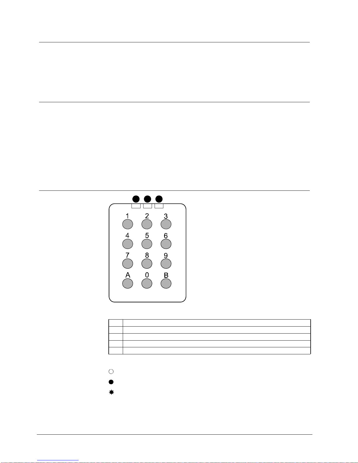
7.6 Keypad..................................................................................................10
7.7 LED status when connecting.................................................................11
7.8 LED status in service mode...................................................................11
7.9 LED Status at battery warning...............................................................11
7.10 Buzzer...................................................................................................12
7.11 Unlock a door........................................................................................12
8Change Administrator code................................................................13
8.1 Present Administrator code is known.....................................................13
8.2 Present Administrator code is not known...............................................14
9System mode.......................................................................................15
9.1 Activate System mode...........................................................................15
9.2 Service mode ........................................................................................16
9.2.1 Check signal strength - A30..................................................................16
9.2.2 Check link reliability – A31.....................................................................16
9.2.3 Reboot the RF30-EM – A32 ..................................................................16
9.2.4 Reconnect the network – A34................................................................16
10 Mounting..............................................................................................17
10.1 Technical details....................................................................................17
10.2 Fitting RF30-EM to the door ..................................................................18
10.2.1 Distance between units .........................................................................19
10.2.2 Test mechanical function of RF30-EM...................................................19
10.2.3 Offline mode..........................................................................................19
10.3 Change batteries...................................................................................19
10.4 Adjust the PIR sensor............................................................................20
11 Stand-alone mode ...............................................................................21
11.1 Add a card.............................................................................................21
11.1.1 Adding a card by reading it....................................................................21
11.1.2 Adding a card by entering its number....................................................22
11.1.3 Log on contiguous series of cards.........................................................23
11.2 Cancel a card........................................................................................24
11.2.1 Cancel a card by reading it....................................................................24

4
Siemens AG
04.2010
11.2.2 Cancel a card by entering its number....................................................24
11.3 Set Group code.....................................................................................25
11.3.1 Enter Group code..................................................................................25
11.3.2 Change Group code..............................................................................26
11.3.3 Delete Group code ................................................................................26
11.4 Lock/unlock door...................................................................................27
11.5 Disable/enable buzzer...........................................................................27
12 Erase memory......................................................................................28
13 Operation .............................................................................................29
13.1 Leaving the premises ............................................................................29
13.2 Automatic resetting................................................................................29
13.3 Access blocking.....................................................................................29
13.4 Backup power supply ............................................................................29
14 Command overview.............................................................................30
15 Troubleshooting..................................................................................32
16 Glossary...............................................................................................33
17 Keyword index.....................................................................................34

Service description
5
Siemens AG
04.2010
1 Service description
RF30-EM is a Scandinavian style Codoor. It can be used as a wireless system
component or as a Stand-alone unit.
2 Safety
2.1 Target group
Target readers Qualification Activity Condition of the
product
Installer Technical training for
building or electrical
installations.
Installs the product,
individual components
of the product or re-
placement parts.
Components of the
product are not yet
installed or need to be
replaced or modified.
Operational startup
personnel Technical training for
building or electrical
installations.
Special knowledge of
the device/system is
required.
Puts the product into
operation for the first
time, or changes the
existing configuration.
The product is installed
but not yet configured,
or the existing configu-
ration is to be changed.
Service personnel Technical training for
building or electrical
installations.
Special knowledge of
the device/system is
required.
Checks the product at
regular intervals to
ensure that it is in good
working order, services
the device or system
and repairs it or ex-
pands and upgrades the
system.
Product already in use
and requiring servicing.
2.2 General safety precautions
Read the general safety precautions before operating the device.
Keep this document for reference.
Always pass this document on together with the product.
Please also take into account any additional country-specific, local safety
standards or regulations concerning project planning, operation and disposal of
the product.
Damage to the device due to electrostatic discharge (ESD)
Always use wrist straps or similar connected to earth.
Damage due to unsuitable mounting location
The device should only be used for indoor applications.

Standards and guidelines
6
Siemens AG
04.2010
3 Standards and guidelines
3.1 EU directives
This product complies with the requirements of the European Directives. The EU
declaration of conformity is available from:
Siemens AG
I BT DE FS SP
76187 Karlsruhe, Germany
EU directives 1999/5/EC R&TTE: “Radio and telecommunications terminal
equipment”
Compliance with the European Directive 1999/5/EC has been proven by testing
according to the following standards:
Electromagnetic compatibility EN 301 489-1
EN 301 489-17
EMC immunity of alarm systems EN 50130-4
Safety EN 60950-1
Radio requirements EN 300 330-2
EN 300 328

Technical data
7
Siemens AG
04.2010
4 Technical data
RF30-EM
Operating voltage Two Lithium 9V type 6LR61 batteries (not in-
cluded).
For a safe function we strongly recommend the use
of our batteries Ultralife UL9V with 9V, 1200 mAh
and sustaining minimum 400 mA peak current.
Operational time Approx. one year
Card technology EM4102 125 kHz
Card capacity In System mode (online): Set by SiPass/Bewator
Entro
In System mode (offline): 250 cards (100 priority
and 150 peronal cards)
In Stand-alone mode: 250 cards
Card read distance 1 to 3 cm (approx.)
Frequency band 2.4 GHz
Indicators 3 x LED (red/yellow/green)
1 x buzzer
Operating temperature 0 to +50 °C
Environment Indoor use only
IP rating IP30
Colour Stainless steel
Dimensions (W x H x D) 285 x 64 x 59 mm
Weight 0.76 kg
Approval CE
NOTE
Lithium batteries must be used because they provide the following advantages:
The capacity is constant throughout battery life.
Longer battery life reduces the environmental impact as fewer batteries are needed.
Battery storage life can be up to ten years.

Details for ordering
8
Siemens AG
04.2010
5 Details for ordering
Type Order No. Designation Weight
RF30-EM GBI:31-118 Codoor 0.76 kg
6 Package contents
Check that you have the following parts before discarding the packing materials:
1 x RF30-EM (batteries excluded).
4 extension sleeves for handle nipples (use only one pair, M4 or M5).
1 x reinforcing spring.
1 x reinforcing spring holder.

Description of Equipment
9
Siemens AG
04.2010
7 Description of Equipment
7.1 Stand-alone mode
In Stand-alone mode you have only one RF30-EM controlling one door.
1. Set the Administrator code. See section 8 Change Administrator code.
2. Program cards and Group codes. See section 11 Stand-alone mode.
7.2 System mode
In System mode you can have more than one RF30-EM integrated in a whole
access control system controlled by the SiPass/Bewator Entro software.
Programming can only be done via the SiPass/Bewator Entro software.
NOTE
Do not mount two RF30-EM units back to back on one door. They cannot both control the door latch.
1. Set the Administrator code. See section 8 Change Administrator code.
2. Activate System mode. See section 9 System mode.
3. Check for communication between the RF30 and the SiPass/Bewator Entro
system. See section 9.2 Service mode
4. Mount the RF30-EM. See section 10 Mounting.
Back to Stand-alone mode
Erase the system settings and return to the factory default condition. See
section 12 Erase memory.
7.3 Mounting
The RF30-EM may be fitted on most doors with handle operated ASSA modular
type mortise locks.
When fitted, the external handle is inoperable until a valid card or code is entered.
The internal handle is not affected and will retract the latch bolt as required.
7.4 Wireless communication
The RF30-EM communicates with a host controller via a radio network. Thus the
RF30-EM operates as a wireless reader in an SiPass/Bewator Entro system. All
communication takes place via a Private Area Network (PAN) where either a SR35i
or a router RF9 transmits information via radio to/from the RF30-EM.

Description of Equipment
10
Siemens AG
04.2010
7.4.1 Antennae
The card reader antenna is integrated in the upper part of the keypad, so cards
and other tags should be presented to the keypad.
The network antenna is located in the grey plastic housing on the lower face of the
RF30-EM.
7.5 Power down and activation
Normal operational use of the RF30-EM will consume power from the batteries.
When the RF30-EM is not in use, the power consumption is reduced to a minimum
to save batteries.
PIR sensor
A passive infra-red (PIR) sensor “wakes up” the reader when it detects a person
close to the RF30-EM. The RF30-EM is thus ready to provide access to the door
via card and/or Group code/PIN. See section 10.4 Adjust the PIR sensor.
7.6 Keypad
1 2 3
Fig. 1 Keypad RF30-EM
Red LED.
Yellow LED.
Green LED.
0-9 Are used for entering codes and/or programming.
A/B Are used only for programming.
In this manual three symbols illustrate how the LEDs are used:
= OFF
= ON
= Flashing

Description of Equipment
11
Siemens AG
04.2010
7.7 LED status when connecting
When the yellow is LED flashing (e g due to wrong segment ID or the
radio connection link is down, press 0 for at least two seconds for detailed error
codes.
Detailed error codes
Address collision
Another RF30-EM might have the same address.
Too many doors in one segment.
Address number is not allowed in this segment. This is depending
on the SR35i range (4/8/16/32). E.g. in a SR35i/4 you can’t use
the Address “5”. See installation manual SiPass/Bewator Entro
Wireless.
Wrong installation key.
For safety reasons the entry is blocked for a while. The installation
key has been entered wrong three times in a row.
System limit of RF30-EM in the system reached. See installation
manual SiPass/Bewator Entro Wireless.
, , , ,… Connecting to the network.
7.8 LED status in service mode
To enter the Service mode see section 9.2 Service mode.
LEDs Declaration
Service mode - Signal strength (command A30)
Signal strength excellent.
Signal strength sufficient.
Signal strength OK.
Recommendation
Relocate the router.
Signal strength weak.
Relocate the router.
Service mode - Link reliability (command A31)
Link reliability OK. Sending and receiving messages.
One or more messages lost.
Recommendation
Relocate the router.
Link unreliability. Messaging took more than 0.7 s.
Relocate the router.
7.9 LED Status at battery warning
First warning level for low battery: Flashing LED and a delay of the unlocking.
Second warning level for low battery: Fast flashing LED on each key press. Door
can be opened only with Administrator code. Loosing connection to the network,
entering Offline mode.

Description of Equipment
12
Siemens AG
04.2010
7.10 Buzzer
RF30-EM also incorporates a buzzer to confirm each key press (if required).
The buzzer also sounds to confirm successful programming.
7.11 Unlock a door
In Stand-alone mode either a card or a code can be used to unlock the door. The
use of a card provides higher security.
In System mode, a card with corresponding code can be used.

Change Administrator code
13
Siemens AG
04.2010
8 Change Administrator code
8.1 Present Administrator code is known
NOTE
The Administrator code cannot be the same as the code 112186 to erase the memory.
See section 12 Erase memory.
If you are in administrator mode and don’t press a key the device will automatically leave the
administrator mode after 30 seconds.
RF30-EM is delivered with the default Administrator code set as 112233.
1. Press B.
2. Enter the 6-digit Administrator code.
3. Press A27.
The buzzer sounds a confirm tune.
4. Enter a new 6-digit Administrator code.
The buzzer sounds a confirm tune.
5. Verify by entering the same Administrator code again.
RF30-EM exits at the Administrator mode.
6. Make a note of the Administrator code.

Change Administrator code
14
Siemens AG
04.2010
8.2 Present Administrator code is not known
NOTE
The Administrator code cannot be the same as the code 112186 to erase the memory.
See section 12 Erase memory.
If you are in administrator mode and don’t press a key the device will automatically leave the
administrator mode after 30 seconds.
1. Remove the RF30-EM from the door.
2. Quickly press the reset button on the back of the RF30-EM.
Fig. 2 Reset button on the back
The buzzer sounds a confirm tune.
3. Enter the desired 6-digit Administrator code.
The buzzer sounds a confirm tune.
4. Verify by entering the same Administrator code again.
The buzzer sounds a confirm tune.
If the second input doesn’t match the first input the buzzer will sound a error
tone and the Administrator code will not be changed.
5. Make a note of the Administrator code.

System mode
15
Siemens AG
04.2010
9 System mode
9.1 Activate System mode
Starting in Stand-alone mode, three parameters must be entered to set the
RF30-EM in System mode:
4-digit Segment ID
2-digit Address
8-digit Installation key
CAUTION Remember to change the Administrator code for safety reasons
If the battery is low the door can be opened with the default Administrator code.
1. Change the Administrator code. See section 8 Change Administrator code.
2. Check in the SiPass/Bewator Entro software which Segment ID, Address and
installation key is used in the SR35i.
3. Press B.
4. Enter the 6-digit Administrator code.
5. Enter A80.
6. Enter the 4-digit Segment ID.
7. Enter the 2-digit Address. (01 - 32)
8. Enter the 8-digit Installation key.
9. Press A.
The RF30-EM will operate in System mode. If any other key than A is pressed
the RF30-EM returns to Stand-alone Administrator mode.
If any of these steps is not performed within 20 seconds the RF30-EM returns to
Administrator mode.
NOTE
If you make errors in steps 6 to 8, press any other key than A in step 9 and start over from step 5.

System mode
16
Siemens AG
04.2010
9.2 Service mode
1. To enter the service mode quickly press key B followed by a long press on
key B and wait until the buzzer confirm.
2. Enter the 6-digit Administrator code
The commands A30, A31, A32 or A34 can then be performed.
3. To leave this mode press B.
9.2.1 Check signal strength - A30
The A30 command displays the signal strength. It will proceed for 5 minutes or until
a key press or card use. Note that although the green LED lit the command A31
should be performed to confirm a reliable data transmission.
LED Description
Signal strength excellent.
Signal strength sufficient.
Signal strength OK.
Recommendation
Relocate the router.
Signal strength bad.
Relocate the router.
9.2.2 Check link reliability – A31
The command A31 displays the reliability of the data transmission. It will proceed
for 5 minutes or until a key press or card use.
Buzzer Description
Continuous tones. Link reliability OK. Sending and receiving messages.
Non continuous
tones. One or more messages lost.
Recommendation
Relocate the router.
Error tone. Link unreliability. Messaging took more then 0.7 s.
Relocate the router.
9.2.3 Reboot the RF30-EM – A32
The command A32 performs a reboot of the firmware in the RF30-EM.
9.2.4 Reconnect the network – A34
The command A34 should be performed if e g a router has been added to the sys-
tem. The system tries to reconnect the RF30-EM to the Segment Controller.

Mounting
17
Siemens AG
04.2010
10 Mounting
10.1 Technical details
NOTE
Do not mount two RF30-EM units back to back on one door. They cannot both control the latch.
RF30-EM is suitable for most doors with handle-operated mortise locks.
The distance between the centre of the handle and the centre of the cylinder
should be between 105 – 116 mm.
Latchbolt function.
The handle must have an 8 mm square spindle.
The handle’s fixing holes should be at 30 – 38 mm centres (diagonal).
The RF30-EM can be used with a variety of locks such as ASSA 8561 or 565.
The backset should be 70 mm.
Backset = 70 mm
Fig. 3 RF30-EM door mounting

Mounting
18
Siemens AG
04.2010
10.2 Fitting RF30-EM to the door
1. Check that the Administrator code has been set. See section 8 Change Ad-
ministrator code.
2. Make sure you have the following tools handy:
– Screwdriver for door handle and cylinder ring screws.
– Hacksaw for trimming lever handle spindle.
3. Remove the cylinder ring and door handle from the door by loosening the four
screws. See figure 1.
4. Ensure that the handle spindle does not project more than 20 mm on the
outside of the door. If the spindle is too long, push it through into the handle
on the inside. If this cannot be done, cut the spindle to the right length. See
figure 2.
5. Prepare the handle by extending the screws with the supplied extension
sleeves (M4 or M5). See figure 3.
6. Place the RF30 on the outside of the door with the handle attached, and pass
the lever handle spindle through the square hole. See figure 4.
7. Ensure that the red mark on the follower point downwards. See figure 5.
8. Tighten the four previously loosened screws to the nipples (the screws for the
handle first). These should be just firm. Over-tightening may distort the lock
structure so that it jams. See figure 6.
9. Test the mechanical function of the RF30-EM. See section 10.2.2 Test
mechanical function of RF30-EM.
1
2
3
4
5
6

Mounting
19
Siemens AG
04.2010
10.2.1 Distance between units
For reliable operation, the distance between the SR35i and the RF30-EM units
must not exceed 25 metres. In that case a RF9 router/amplifier must be installed.
You can read more about this in the installation guide supplied with the RF9. Note
that electrical interference or noise may also reduce the working range of the
wireless link. See SiPass/Bewator Entro Wireless intstallation manual.
10.2.2 Test mechanical function of RF30-EM
It must always be possible to open the door from the inside.
Check that the PIR sensor will detect a person and activate the electronics. This
means that nothing limits the detection area of the sensor.
The handle on the outside should not be engaged, and should not open the door
until the correct card/code is entered.
When the correct card/code is entered, the handle on the outside should activate
the lock, but only once. As the handle is released, it should again disengage.
If the correct card/code is entered but the handle is not pressed down, the RF30-
EM should automatically disengage the handle after about 4 seconds.
The handle on the outside must not be jammed in any position, and should
spring back up completely after being pressed down.
10.2.3 Offline mode
In normal operation the host system controls the validity of the cards. If the
RF30-EM loses contact with the system it will operate offline in offline mode. The
yellow LED will flash slowly, if the RF30-EM has never had a connection to the
system.
In this mode the RF30-EM accepts up to 250 cards stored in internal memory.
These are known as Priority Cards and are identical to the priority cards in
SiPass/Bewator Entro. The priority cards are regularly downloaded from the
system when the RF30-EM is on-line (see section 7.7 LED status when
connecting.
If the red LED flashes and the buzzer sounds when reading a card this means that
the card is not valid in offline mode.
10.3 Change batteries
When the unit’s batteries run flat the RF30-EM will cease to release the latch so
the unit should be fitted with cylinder override. The lock has a backup power supply
that will allow the door to be opened a limited number of times, but the batteries
should be replaced as soon as the low battery warning is noticed. See sections
7.7 LED status, 11.5 Disable/enable buzzer and 13.4 Backup power supply. The
card memory of the RF30-EM is retained while the batteries are flat and while the
batteries are being replaced.
1. Remove the RF30-EM from the door.
2. Remove the two batteries from the rectangular shaped holes on the lower part
of the back of the unit (to power off the unit).
3. Always change both batteries at the same time. See section 4 Technical data.
4. Re-mount the RF30-EM.

Mounting
20
Siemens AG
04.2010
10.4 Adjust the PIR sensor
Depending on the environment it could be necessary to adjust the PIR sensor.
Remember to do this carefully and keep the sensor while the screw is adjusted.
Fig. 4 RF30-EM – PIR sensor and screw to adjust the PIR sensor
Minimize the PIR sensor radius
The door is located in a busy environment for example stores or corridors.
1. Turn the screw anticlockwise.
The sensor moves down.
Extend the PIR sensor radius
The door will be opened from the side instead of the front.
1. Turn the screw to the right.
The sensor moves up.
Table of contents
Languages:
Other Siemens Door Lock manuals
Popular Door Lock manuals by other brands

ZKTeco
ZKTeco LH7000 installation guide

24/7 HOME SECURITY
24/7 HOME SECURITY PDL247 Installation

Allegion
Allegion Falcon MA Series installation instructions

CEStronics
CEStronics Omega Flex Assembly and operating manual

Weiser
Weiser PowerboIt 3 Installation and user guide

Easy Access
Easy Access EASYCODETOUCH manual