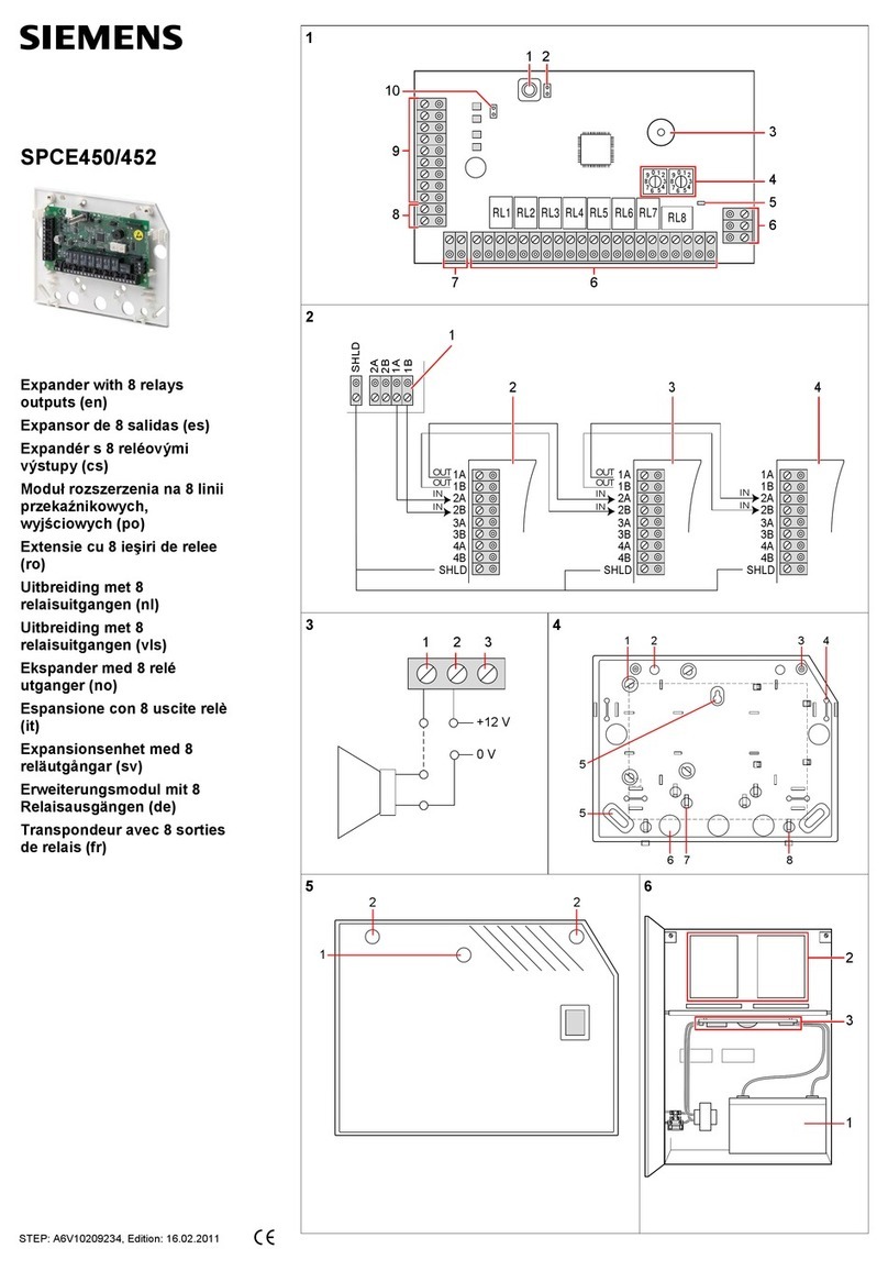
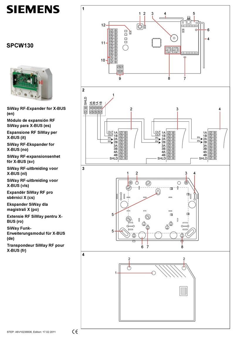
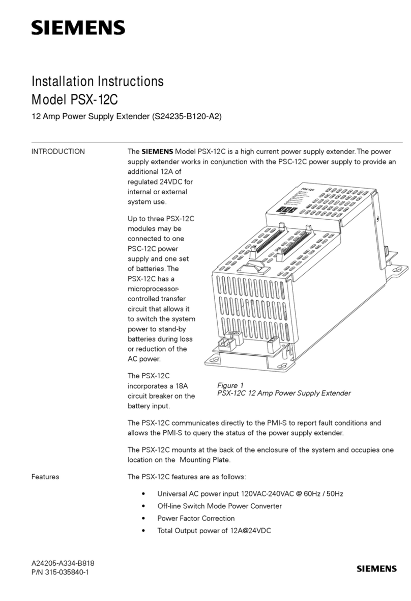
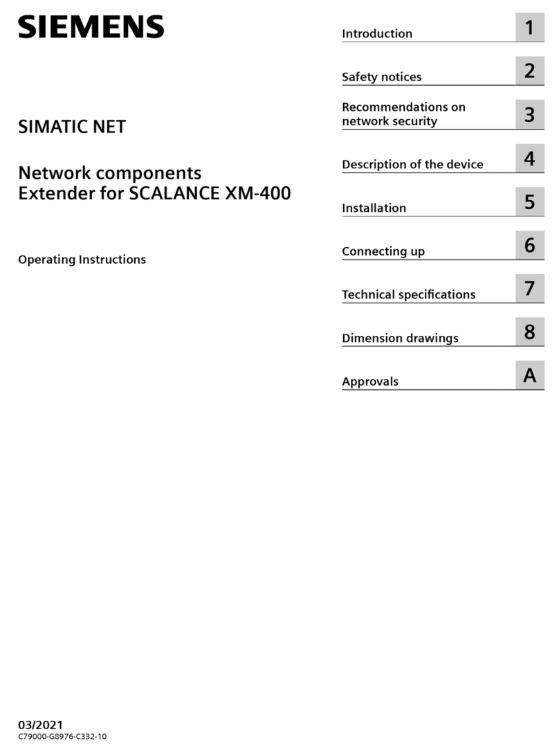
Siemens 6ES7 972-4AA02-0XA0 User manual

Artisan Technology Group is your source for quality
new and certied-used/pre-owned equipment
• FAST SHIPPING AND
DELIVERY
• TENS OF THOUSANDS OF
IN-STOCK ITEMS
• EQUIPMENT DEMOS
• HUNDREDS OF
MANUFACTURERS
SUPPORTED
• LEASING/MONTHLY
RENTALS
• ITAR CERTIFIED
SECURE ASSET SOLUTIONS
SERVICE CENTER REPAIRS
Experienced engineers and technicians on staff
at our full-service, in-house repair center
WE BUY USED EQUIPMENT
Sell your excess, underutilized, and idle used equipment
We also offer credit for buy-backs and trade-ins
www.artisantg.com/WeBuyEquipment
REMOTE INSPECTION
Remotely inspect equipment before purchasing with
our interactive website at www.instraview.com
LOOKING FOR MORE INFORMATION?
Visit us on the web at www.artisantg.com for more
information on price quotations, drivers, technical
specications, manuals, and documentation
Contact us: (888) 88-SOURCE | sales@artisantg.com | www.artisantg.com
SM
View
Instra

User´s Guide Power Rail Booster Version 12/2005
Copyright ©Siemens AG 2005 All rights reserved. 6ES7 972-4AA02-0XA0 Page 1 of 49
Power Rail Booster
User’s Guide
Version 12/2005
Artisan Technology Group - Quality Instrumentation ... Guaranteed | (888) 88-SOURCE | www.artisantg.com
User´s Guide Power Rail Booster Version 12/2005
Copyright ©Siemens AG 2005 All rights reserved. 6ES7 972-4AA02-0XA0 Page 2 of 49
Exclusion of liability
We have checked the contents of this manual for agreement with the
hardware and software described. Since deviations cannot be precluded
entirely, we cannot guarantee full agreement. However, the data in this
manual are reviewed regularly and any necessary corrections included in
subsequent editions. Suggestions for improvement are welcomed.
Copyright
Copyright ©Siemens AG 2005. All rights reserved.
The reproduction, transmission or use of this document or its content is
not permitted without express written authority.
Offenders will be liable for damages. All rights, including rights created
by patent grant or registration of a utility model or design, are reserved.
Technical specifications are subject to change without prior notice.
Artisan Technology Group - Quality Instrumentation ... Guaranteed | (888) 88-SOURCE | www.artisantg.com
User´s Guide Power Rail Booster Version 12/2005
Copyright ©Siemens AG 2005 All rights reserved. 6ES7 972-4AA02-0XA0 Page 3 of 49
Foreword
Purpose of this manual
This manual provides an overview of the Power Rail Booster for
PROFIBUS-DP and supports users in configuration, installation
and commissioning.
It is directed at persons, whose work involves the configuration,
commissioning and/or servicing of automation systems.
Basic knowledge requirements
General knowledge in the field of automation is required to use
this manual.
Validity of this manual
The manual is designed for use with the Power Rail Booster for
PROFIBUS-DP with the order No. 6ES7 972-4AA02-0XA0.
This manual describes components that are valid at the time of
publishing. We reserve the right to include current product
information on any new components and components with a
newer release level.
Comparison with the previous version
The previous version of this manual was revised and
supplemented to create this latest version:
•“General Remarks” revised and Table “Overview of
Compatibility with Previous Versions” supplemented.
•Chapter 2 „Introduction“ revised.
•Chapter 3.2.3 „LED Test on Activating the Voltage Supply“
added.
•Chapter 3.3 „Mode-dependent Functions“ added.
•Chapter 4.3.1 „Cascading“ revised.
•Chapter 4.3.2 „Point-to-point Connection” revised.
•Chapter 4.4 „Rail Sections“ revised.
•Chapter 5.2 „Configuration with the PRB Checker“ revised.
•Chapter 5.3 „Configuration of the Bus Parameters“ revised.
•Chapter 6.3.2 „Interfaces and Connections“ revised.
•Chapter 7.1 „Diagnostic Displays fort he PRB“ revised.
•Chapter 7.2 „Diagnostics Message Frame“ added.
•Chapter 8 „Technical Specifications“ revised.
•Chapter 9.1 „Additional Hardware and Hardware for PRB
Applications“ replaced by Chapter 9.1 „Examples for
Applications“ of the previous version.
•Chapter 10 „Standards and Certifications“ added.
Artisan Technology Group - Quality Instrumentation ... Guaranteed | (888) 88-SOURCE | www.artisantg.com
User´s Guide Power Rail Booster Version 12/2005
Copyright ©Siemens AG 2005 All rights reserved. 6ES7 972-4AA02-0XA0 Page 4 of 49
Certification See the Chapter on Standards and Certifications.
CE Compliance See the Chapter on Standards and Certifications.
Standards See the Chapter on Standards and Certifications.
SIMATIC Technical Support, Contacts and Training Courses
For more information visit us on the Internet:
http://support.automation.siemens.com
Overview of “Compatibility with Previous Versions“
Function/Properties 6ES7 972-4AA02-0XA0 6ES7 972-4AA01-0XA0 6ES7 972-4AA00-0XA0
Housing Plastic Plastic Metal
Dimensions W x H x D (mm)
Incl. plugs with assembly to 7.5 mm
Top-hat rail
Minimum installation space W x H x D
(mm)
90x132x75
90x165x75
90x132x75
90x165x75
120x110x135
120x170x135
Terminal connectors
Power Rail
DC24 SF signalling contact
Pluggable
Max. cross-section: 2.5 sqmm
max. cross-section: 2.5 sqmm
Pluggable
Max. cross-section: 2.5 sqmm
Integrated
Max. cross-section: 2.5 sqmm
Max. cross-section: 4.0 sqmm
Hybrid operation permissible with PRB: 6ES7 972-4AA00-0XA0
6ES7 972-4AA01-0XA0 6ES7 972-4AA02-0XA0 6ES7 972-4AA02-0XA0
SF signalling contact Non-wearing semi-
conductor: 24..230V UC /
0.2A
Relay
24..230V UC / 2A Relay
24..230V UC / 6A
Cascadeable Yes, up to 10 PRBs in
series Yes, up to 10 PRBs in series No
UL-approved Yes No Yes
Operating modes of SF relay
Signalling contact / diagnostics
Yes / yes, product release 3
and above 3
Yes / no
Yes / no
Artisan Technology Group - Quality Instrumentation ... Guaranteed | (888) 88-SOURCE | www.artisantg.com
User´s Guide Power Rail Booster Version 12/2005
Copyright ©Siemens AG 2005 All rights reserved. 6ES7 972-4AA02-0XA0 Page 5 of 49
C o n t e n t s
1GENERAL REMARKS ............................................................................................................ 7
2INTRODUCTION ..................................................................................................................... 9
2.1 APPLICATIONS ........................................................................................................................... 9
3GENERAL FUNCTIONS........................................................................................................ 11
3.1 BASIC FUNCTION...................................................................................................................... 11
3.2 FUNCTIONS.............................................................................................................................. 11
3.2.1 SUPPORTED PROTOCOLS ......................................................................................................... 11
3.2.2 TRANSMISSION SPEED.............................................................................................................. 11
3.2.3 LED TEST ON ACTIVATING THE VOLTAGE SUPPLY....................................................................... 12
3.2.4 SIGNAL REGENERATION............................................................................................................ 12
3.2.5 SHORT CIRCUIT DETECTION...................................................................................................... 12
3.2.6 MONITORING OF THE OUTPUT TEMPERATURE............................................................................ 12
3.2.7 COMMISSIONING AIDS............................................................................................................... 12
3.3 SETTABLE ADDITIONAL FUNCTIONS (PRODUCT RELEASE 3AND ABOVE)........................................ 12
3.3.1 DISPLAY OF THE FIRMWARE VERSION ........................................................................................ 12
3.3.2 CONTROLLING THE "IS-MASTER"SIGNAL.................................................................................... 13
3.3.3 DIAGNOSTIC MESSAGE............................................................................................................. 13
4NETWORK TOPOLOGIES FOR CONTACT RAIL SYSTEMS.............................................. 14
4.1 TERM DEFINITIONS................................................................................................................... 14
4.2 INTRODUCTION......................................................................................................................... 15
4.3 EXAMPLES OF TOPOLOGIES ...................................................................................................... 15
4.3.1 CASCADING ............................................................................................................................. 15
4.3.2 POINT-TO-POINT CONNECTION.................................................................................................. 15
4.3.3 LINE TOPOLOGY....................................................................................................................... 16
4.3.4 STAR TOPOLOGY ..................................................................................................................... 16
4.3.5 CLOSED RING CIRCUITS ........................................................................................................... 17
4.4 RAIL SECTIONS........................................................................................................................ 18
5CONFIGURATION................................................................................................................. 19
5.1 PROCEDURE............................................................................................................................ 19
5.2 CONFIGURATION WITH THE „PRB CHECKER“.............................................................................. 21
5.3 CONFIGURATION OF THE BUS PARAMETERS ............................................................................... 23
5.3.1 CONFIGURING THE PARAMETER:„NUMBER OF OLMS “................................................................ 23
5.3.2 ADAPTING THE„RETRY LIMIT“PARAMETER ................................................................................. 24
5.4 CONFIGURING THE CONTACT RAILS AND SLIDING CONTACTS....................................................... 24
5.4.1 INTRODUCTION......................................................................................................................... 24
5.4.2 CONTACT RAIL CAPACITANCE ................................................................................................... 24
5.4.3 CONTACT RESISTANCE BETWEEN CONTACT RAILS AND SLIDING CONTACTS ................................. 24
5.4.4 PREFERRED ARRANGEMENT OF THE CONTACT CONDUCTORS ..................................................... 25
5.4.5 PREFERRED ARRANGEMENT OF THE WIRES IN CABLES ................................................................ 26
6COMMISSIONING................................................................................................................. 27
6.1 SAFETY INFORMATION .............................................................................................................. 27
6.2 GENERAL INFORMATION REGARDING COMMISSIONING................................................................. 28
6.3 INSTALLATION .......................................................................................................................... 29
6.3.1 INSTALLING A PRB................................................................................................................... 29
6.3.2 INTERFACES AND CONNECTOR PIN ASSIGNMENT ........................................................................ 30
6.3.2.1 GRAPHICAL INTERFACE DIAGRAM,GALVANIC ISOLATION ...................................................... 30
6.3.2.2 WIRING GUIDELINES FOR INTERFACES ............................................................................... 30
6.3.2.3 CONNECTING THE POWER RAIL INTERFACE........................................................................ 31
6.3.2.4 CONNECTING THE PROFIBUS INTERFACE ........................................................................ 31
Artisan Technology Group - Quality Instrumentation ... Guaranteed | (888) 88-SOURCE | www.artisantg.com
User´s Guide Power Rail Booster Version 12/2005
Copyright ©Siemens AG 2005 All rights reserved. 6ES7 972-4AA02-0XA0 Page 6 of 49
6.3.2.5 CONNECTING THE OPERATING VOLTAGE ............................................................................ 31
6.3.2.6 CONNECTING THE SIGNALLING CONTACTS.......................................................................... 32
6.3.2.7 CONNECTION SCHEME FOR WIRING PRB ........................................................................... 32
6.4 DETERMINING THE TRANSFER RESISTANCE OF COLLECTORS....................................................... 33
6.4.1.1 MEASURING INDIVIDUAL RESISTANCES............................................................................... 33
6.4.1.2 MEASURING THE SERIES RESISTANCES ON INDIVIDUAL DOUBLE SLIDING CONTACTS ............... 33
6.4.1.3 MEASURING THE SERIAL RESISTANCES ON BOTH DOUBLE SLIDING CONTACTS ....................... 33
7LED DISPLAY AND TROUBLESHOOTING ......................................................................... 34
7.1 DIAGNOSTIC DISPLAYS FOR THE POWER RAIL BOOSTER ............................................................. 34
7.2 DIAGNOSTICS MESSAGE FRAME................................................................................................ 35
7.2.1 MESSAGE FRAME STRUCTURE.................................................................................................. 35
7.2.2 CONTENTS OF THE MESSAGE FRAME......................................................................................... 35
7.2.3 TIMING .................................................................................................................................... 36
7.3 FAULT SCENARIOS IN A DP MASTER SYSTEM WITH PRBS........................................................... 36
8TECHNICAL SPECIFICATIONS ........................................................................................... 37
9APPENDIX ............................................................................................................................ 39
9.1 ADDITIONAL HARDWARE AND SOFTWARE FOR PRB APPLICATIONS .............................................. 39
9.1.1 PRB SEGMENT CONTROLLER ................................................................................................... 39
9.1.2 UPDATE MANAGER FOR APPLICATIONS WITH OVERHEAD CONVEYOR ........................................... 41
9.1.3 S7 –FUNCTION BLOCK “PRB DIAGNOSTICS“ ............................................................................. 42
10 STANDARDS AND CERTIFICATIONS................................................................................. 43
11 GLOSSARY........................................................................................................................... 45
12 LIST OF FIGURES ................................................................................................................ 49
Artisan Technology Group - Quality Instrumentation ... Guaranteed | (888) 88-SOURCE | www.artisantg.com
User´s Guide Power Rail Booster Version 12/2005
Copyright ©Siemens AG 2005 All rights reserved. 6ES7 972-4AA02-0XA0 Page 7 of 49
1 General Remarks
Safety-related
remarks
This User’s Guide contains warnings that you must observe for
your own personal safety as well as to avoid material damage. The
warnings are emphasized by a warning triangle and appear as
follows in dependence of the danger level:
U
Danger
This means that death, serious injury or substantial material
damage will occur if the prescribed precautionary measures are
not taken.
U
Warning
This means that death, serious injury or substantial material
damage may occur if the prescribed precautionary measures are
not taken.
U
Caution
This means that minor injuries or light material may occur if the
prescribed precautionary measures are not taken.
Note
Provides important information about the product, the handling of
the product or about a specific part of the documentation to which
attention needs to be called.
Artisan Technology Group - Quality Instrumentation ... Guaranteed | (888) 88-SOURCE | www.artisantg.com
User´s Guide Power Rail Booster Version 12/2005
Copyright ©Siemens AG 2005 All rights reserved. 6ES7 972-4AA02-0XA0 Page 8 of 49
Qualified
personnel
A device may be put into operation or operated only by qualified
personnel. For the purpose of this manual, qualified personnel are
persons who are authorized to put into operation, ground and
designate devices, systems and electrical circuits according to the
safety-related standards.
Control cabinet
For the purposes of this User’s Guide, a control cabinet must fulfil
the fire enclosure requirements to EN 60950.
U
Warning
The device is intended for operation in control cabinets or closed
equipment rooms.
The device may not be opened.
U
Warning
The configuring engineer is always responsible for ensuring that
data transmission errors cannot produce a dangerous situation. In
the case of systems connected by contact conductors, it is not
possible to exclude brief interruptions to communication due to the
mechanical link of the electrical transfer paths. The control
software must take this into account.
Use as
prescribed
The device may be used only for the applications described in this
Guide and only in conjunction with non-Siemens devices and
components recommended or authorized by Siemens.
Proper transport, storage and installation as well as careful
operation and maintenance of the device are prerequisites for
problem-free and safe operation.
Artisan Technology Group - Quality Instrumentation ... Guaranteed | (888) 88-SOURCE | www.artisantg.com
User´s Guide Power Rail Booster Version 12/2005
Copyright ©Siemens AG 2005 All rights reserved. 6ES7 972-4AA02-0XA0 Page 9 of 49
2 Introduction
The PRB (Power Rail Booster) is intended for use as a network component in
electrical PROFIBUS networks. Its purpose is the amplification and safe, reliable
transmission of PROFIBUS signals. The PRB enables the transmission of
PROFIBUS signals over contact rails, loops and other cable types (such as
telephone cables) not compliant with the PROFIBUS Specification. The PRB also
enables data transmission in the face of an excessive EMC load.
The PRB can be easily integrated in existing PROFIBUS fieldbus networks. It is also
possible to configure a complete PROFIBUS fieldbus network in line and/or star
topology. Except for the Power Booster itself, no other filters or terminating elements
are required for safe, reliable data transmission. In the case of increased EMC
loading above the limit values stated in the technical specifications, using
interference suppressor filters can allow you to achieve higher limit values.
Every PRB has two independent, isolated interfaces, each in turn consisting of a
transmitter component and a receiver component.
The primary channel is designated as 9-pin D subminiature (female) socket
connector. An RS 485 bus segment to PROFIBUS Standard EN 50170 can be
connected to this channel.
The secondary channel is run to a terminal strip. There are two pins for each signal
(A1, A2 and B1, B2). A power rail segment can be connected to this channel. The
nominal cross-sectional area measures 2,5mm².
LEDs signal the current status as well as any malfunctions.
The operating voltage supply comes from 24 V direct voltage.
At least two Power Rail Boosters are required for a transmission link.
2.1 Applications
Primary applications for the Power Rail Booster include:
-Motor-driven overhead trolley conveyors,
-Storage/retrieval devices,
-Crane installations,
-Rotary feed through units and rotary tables,
-Lifts and hoisting apparatus,
-Traversing tracks.
It is also generally recommended that the Power Rail Booster be used for cost-
efficient, safe and reliable PROFIBUS transmissions via contact rails or cables.
Artisan Technology Group - Quality Instrumentation ... Guaranteed | (888) 88-SOURCE | www.artisantg.com
User´s Guide Power Rail Booster Version 12/2005
Copyright ©Siemens AG 2005 All rights reserved. 6ES7 972-4AA02-0XA0 Page 10 of 49
The following illustration shows a sample application.
Fig. 1: Sample application of the Power Rail Booster
Artisan Technology Group - Quality Instrumentation ... Guaranteed | (888) 88-SOURCE | www.artisantg.com

User´s Guide Power Rail Booster Version 12/2005
Copyright ©Siemens AG 2005 All rights reserved. 6ES7 972-4AA02-0XA0 Page 11 of 49
3 General Functions
3.1 Basic Function
The basic functionality of the Power Rail Booster is safe, reliable, bidirectional data
transmission. Following power-up, the PRB begins an automatic search for the baud
rate. Data transmission is activated as soon as a valid baud rate is found. If the
master then sends a request to its slave, data coming in over the RS485 interface
are received by the stationary PRB, elevated to a noise-free level, and sent to the
moving PRB on the power rail side, which receives the data, converts them to the
RS485 level and sends them to the slave. The slave’s response to the master is
transferred the same manner, but in reverse order.
3.2 Functions
These are the functions which are permanently executed or supported by the Power
Rail Booster.
3.2.1 Supported Protocols
The PRB is designed for use as a network component in electrical PROFIBUS
networks. It is a pure transformer, and is largely transparent as PROFIBUS device. It
has no PROFIBUS address. Messages are checked for syntax, but the data are not
checked for correctness as regards their content. The Power Rail Booster supports
mono- and multi-master systems. PROFIBUS DP/FMS, as well as FDL and MPI, are
transferred as protocols.
U
Warning
If there are active stations on both sides of the power rail section,
all stations are at risk of a brief failure in the wake of line
interruptions.
3.2.2 Transmission Speed
The Power Rail Booster supports the following EN 50170-compliant transmission
speeds (baud rates):
9,6 kBit/s, 19,2 kBit/s, 45,45 kBit/s, 93,75 kBit/s, 187,5 kBit/s and 500 kBit/s
The transmission speed is set automatically as soon as the Power Rail Booster
receives valid messages over an interface. If the transmission speed is not yet
known, the outputs for all interfaces are disabled. The PRBs recognize any changes
in the transmission speed during operation and reconfigure themselves accordingly.
Brief transmission problems may occur at the moment of switch-over.
Artisan Technology Group - Quality Instrumentation ... Guaranteed | (888) 88-SOURCE | www.artisantg.com

User´s Guide Power Rail Booster Version 12/2005
Copyright ©Siemens AG 2005 All rights reserved. 6ES7 972-4AA02-0XA0 Page 12 of 49
3.2.3 LED Test on activating the Voltage Supply
When you power up, the PRB activates the LEDs on the front for approximately 1
second.
3.2.4 Signal Regeneration
The PRB regenerates the signal waveshape of the data received, making it possible
to cascade as many as 10 PRBs. The signal throughput time is max. 6 tbit per PRB.
3.2.5 Short Circuit Detection
The Power Rail interface on the PRB is monitored for short circuits. If a short circuit is
detected, the transmitter components are shut down. When the problem has been
rectified, they are automatically put back into operation as described in Chapter 3.1
„Basic Function“. Critical states are signalled as described in Chapter 7 „LED display
and troubleshooting“.
3.2.6 Monitoring of the Output Temperature
The output element is protected against overload by a temperature monitor. The
monitor shuts the output element down when a critical temperature is exceeded.
When the output has cooled down, the PRB automatically restarts data transmission.
Critical states are signalled as described in Chapter 7 „LED Display and
Troubleshooting“.
3.2.7 Commissioning Aids
At least one active station is required to test the Power Rail connection during
installation. That station is usually the PROFIBUS master on the stationary side of
the Power Rail. This station serves as message source. On power-up, the Power Rail
Boosters are passive. They recognize the transmission speed based on the
messages sent by the station. The diagnostic LEDs on the front of the Power Rail
Booster provide a visual aid.
3.3 Settable Additional Functions (product Release 3 and above)
You can activate various additional functions using the DIP switch.
3.3.1 Display of the Firmware Version
Users can activate display of the firmware version on the PRB using DIP switch "DIP-
4".
•DIP-4 Æ„OFF“: displaying the firmware version is deactivated
•DIP-4 Æ„ON“: displaying the firmware version is activated
When display of the firmware version is activated, the LEDs have the following
meanings:
•LED „ϑ“ = “ON” corresponds to 20
•LED „PR“ = “ON” corresponds to 21
•LED „DP“ = „ON“ corresponds to 22
Artisan Technology Group - Quality Instrumentation ... Guaranteed | (888) 88-SOURCE | www.artisantg.com

User´s Guide Power Rail Booster Version 12/2005
Copyright ©Siemens AG 2005 All rights reserved. 6ES7 972-4AA02-0XA0 Page 13 of 49
3.3.2 Controlling the "IS-Master" signal
When deploying several nodes with an active interface, customers must set DIP
switches DIP7 and DIP8 in accordance with the following Table.
Active node stationary Passive node stationary
At least one
active node
travelling
With all stationary PRBs
DIP-7ÆON, DIP-8ÆON
With all travelling PRBs
DIP-7ÆON, DIP-8ÆOFF
With all stationary PRBs
DIP-7 ÆON, DIP-8 ÆON
With all travelling PRBs
DIP-7 ÆON, DIP-8 ÆOFF
Only passive
nodes
travelling
With all stationary PRBs
DIP-7 ÆOFF, DIP-8 ÆOFF
With all travelling PRBs
DIP-7 ÆOFF, DIP-8 ÆOFF
(Factory default setting)
Fig. 2: Setting of DIP switches for controlling the "IS-Master" signal
If the structure of the Power Rail network is a "point-to-point connection", as
described in Chapter 4.3.2, you must set DIP switches DIP-7 and DIP-8 to "ON" on
both the stationary and travelling PRB.
3.3.3 Diagnostic Message
Using DIP switch "DIP-6", users can choose between two diagnostics modes.
•DIP-6 Æ„OFF“: The electronic signalling contact maps the behaviour of the
SF-LED as described in the Table in Chapter 7.1 "Diagnostic
Displays of the Power Rail Booster"
For a detailed description of the behaviour and assignment of the signalling contact
refer to Chapter 6.3.2 “Interfaces and Connections".
•DIP-6 Æ„ON“: The system reports detected errors via the electronic
signalling contact as a serial message frame. This allows you
to make a more exact differentiation between the causes of
errors.
For a more detailed description of the diagnostics message frame refer to Chapter
7.2 "Diagnostics message frame".
Artisan Technology Group - Quality Instrumentation ... Guaranteed | (888) 88-SOURCE | www.artisantg.com

User´s Guide Power Rail Booster Version 12/2005
Copyright ©Siemens AG 2005 All rights reserved. 6ES7 972-4AA02-0XA0 Page 14 of 49
4 Network Topologies for Contact Rail Systems
4.1 Term Definitions
Contact Rail System
The communication between stationary plant control system and mobile vehicles
takes place over PROFIBUS DP. Signals from the master are amplified by the PRB
and fed into the contact rails. The vehicle picks off the amplified signals with the
collector. The moving PRB then transforms the signals back to the Standard
PROFIBUS signal level.
DP Master Segment
A contact rail system can be connected to the PROFIBUS via one or more than one
PROFIBUS master. The segment of a contact rail system in which data interchange
takes place via a PROFIBUS master is referred to as a “DP master segment”.
Normally, a contact rail system consists of only one DP master segment. If there are
multiple DP master segments, care must be taken to see that no electrical
connection (short circuit) can be established between DP master segments via the
double collector. This can be done using rail sections (see Chapter 4.4 „Rail
sections“).
PRB Segment
As a rule, more than one stationary Power Rail Booster is required to supply a
contact rail system with PROFIBUS signals. The subsegment of a contact rail system
in which data interchange takes place via a PRB is referred to as “PRB segment”. A
PRB segment is thus a subsegment of a DP master segment. It must be ensured that
no electrical connection (short circuit) can be established between two PRB
segments via the double collector. This can be done using rail sections (see Chapter
4.4 „Rail sections“).
Fig. 3: Block diagram of a DP master segment with two PRB segments
Artisan Technology Group - Quality Instrumentation ... Guaranteed | (888) 88-SOURCE | www.artisantg.com

User´s Guide Power Rail Booster Version 12/2005
Copyright ©Siemens AG 2005 All rights reserved. 6ES7 972-4AA02-0XA0 Page 15 of 49
4.2 Introduction
The following network topologies can be implemented using the Power Rail Booster:
-Cascading of Power Rail sections,
-Point-to-point connections
-Line topology
-Star topology (contact rail system)
-Closed loop
Combinations of the above are also possible. Two contact rails or cable strands are
used to set up the Power-Rail sections for these network topologies. All cabling or
wiring for the contact rails must be done with PROFIBUS cable.
4.3 Examples of Topologies
4.3.1 Cascading
The PRB regenerates the signal waveshape of the data received, making it possible
to cascade as many as 10 PRBs. You must consider the increased signal throughput
time (6 T-bits per PRB) when configuring in STEP 7, see Chapter 5.3.1!
Fig. 4: Example of cascading
4.3.2 Point-to-point Connection
This configuration is distinguished by the fact that only one PRB is installed on each
side of the Power Rail section. To optimize interference immunity, users must set the
"IS-Master" signal on both PRBs. To do this, you must set on both PRBs DIP
switches DIP-7 and DIP-8 to "ON".
Fig. 5: Example of a point-to-point connection
Artisan Technology Group - Quality Instrumentation ... Guaranteed | (888) 88-SOURCE | www.artisantg.com

User´s Guide Power Rail Booster Version 12/2005
Copyright ©Siemens AG 2005 All rights reserved. 6ES7 972-4AA02-0XA0 Page 16 of 49
4.3.3 Line Topology
This configuration is distinguished by the fact that multiple contact rail segments are
cabled as one line and multiple PRBs are installed on the moving side.
Fig. 6: Example of line topology
4.3.4 Star Topology
This configuration is distinguished by the fact that multiple contact rail segments are
cabled in a star structure and that more than one PRB is installed on the moving
side. The star structure is permissible on no more than two levels (paths and
branches.
Fig. 7: Example of star topology
Artisan Technology Group - Quality Instrumentation ... Guaranteed | (888) 88-SOURCE | www.artisantg.com
User´s Guide Power Rail Booster Version 12/2005
Copyright ©Siemens AG 2005 All rights reserved. 6ES7 972-4AA02-0XA0 Page 17 of 49
4.3.5 Closed Ring Circuits
When using systems with closed loops, it is recommended to establish a low-
resistance connection to ground with the steel construction parallel to the contact rail.
Fig. 8: Example of a closed loop
Artisan Technology Group - Quality Instrumentation ... Guaranteed | (888) 88-SOURCE | www.artisantg.com
User´s Guide Power Rail Booster Version 12/2005
Copyright ©Siemens AG 2005 All rights reserved. 6ES7 972-4AA02-0XA0 Page 18 of 49
4.4 Rail Sections
Two types of rail section (Fig.: 9 and 10) can be used. A double rail section can
maintain communication even during a segment change through suitable switching of
the PRB segments by an PRB Segment Controller.
Fig. 9: Example of a double rail section
The isolating rail section is the cost-optimized solution for a segment change. Here,
the contact rails in the two segments are separated by a non-conductive section. In
this case, the plant controller and the vehicle cannot communicate during the
transition.
Fig. 10: Example of an isolating rail section
The isolating rail section can be created by isolating the contact rail with a suitable
isolator. In addition to isolating properties, it is also necessary to take into account
mechanical properties, particularly those relating to abrasion.
Another way of creating an isolating rail section is to use an isolator instead of a
conductor as contact rail.
U
Note
When installing rail sections, care must be taken when aligning the
junctions in order to avoid bounce.
Artisan Technology Group - Quality Instrumentation ... Guaranteed | (888) 88-SOURCE | www.artisantg.com

User´s Guide Power Rail Booster Version 12/2005
Copyright ©Siemens AG 2005 All rights reserved. 6ES7 972-4AA02-0XA0 Page 19 of 49
5 Configuration
5.1 Procedure
Configuration is handled in steps with the aid of the „PRB-Checker“ tool and
application-specific data as described below.
1. Checking to see whether there is a need for dividing the layout into multiple DP
master segments.
Prerequisites:
-Knowledge of the total number of vehicles in the plant
-Knowledge of the maximum permissible typical bus cycle time for the
application
Division of the layout is always required when:
-there are more than 125 vehicles in the plant
or
-shorter typical bus cycle times are required
or
-the base load of the infeed PRB is to be reduced
Result:
-Number of DP master segments
-Transmission speed used.
2. Checking to see whether there is a need to divide the number of DP master
segments specified in Step 1 into multiple PRB segments. This step must be
performed separately for each DP master segment specified in Step 1.
Prerequisites:
-Results from Step 1
-„PRB Checker“ configuring tool
-Layout of the plant with dimensions
-Number of slaves in the relevant DP master segment
-Number of vehicles in the relevant PRB segment. Each Power Rail Segment
Controller connected to the segment also has to be treated as vehicle.
-Length of the cable between collector and vehicle
-Maximum length of the data in the input/output bytes to be interchanged
between stationary control system and vehicle control system.
Division is always required when it is not possible
-to supply the entire rail length of the relevant DP master segment
or
-to supply the maximum possible number of vehicles in the relevant DP
master segment
with a stationary PRB.
Artisan Technology Group - Quality Instrumentation ... Guaranteed | (888) 88-SOURCE | www.artisantg.com
Table of contents
Other Siemens Extender manuals

Siemens
Siemens PSX-12 User manual

Siemens
Siemens PAD-3 User manual

Siemens
Siemens PAD-4 User manual

Siemens
Siemens SPCE110 User manual

Siemens
Siemens PSX-12C User manual

Siemens
Siemens 505-2571 User manual

Siemens
Siemens SPCE120 User manual

Siemens
Siemens SIMATIC NET PE408 User manual

Siemens
Siemens SPCE450 User manual

Siemens
Siemens SPCW130 User manual