Siemens PSX-12C User manual

A24205-A334-B818
P/N 315-035840-1
12 Amp Power Supply Extender (S24235-B120-A2)
Installation Instructions
Model PSX-12C
Figure 1
PSX-12C 12 Amp Power Supply Extender
INTRODUCTION The SIEMENS Model PSX-12C is a high current power supply extender.The power
supply extender works in conjunction with the PSC-12C power supply to provide an
additional 12A of
regulated 24VDC for
internal or external
system use.
Up to three PSX-12C
modules may be
connected to one
PSC-12C power
supply and one set
of batteries.The
PSX-12C has a
microprocessor-
controlled transfer
circuit that allows it
to switch the system
power to stand-by
batteries during loss
or reduction of the
AC power.
The PSX-12C
incorporates a 18A
circuit breaker on the
battery input.
The PSX-12C communicates directly to the PMI-S to report fault conditions and
allows the PMI-S to query the status of the power supply extender.
The PSX-12C mounts at the back of the enclosure of the system and occupies one
location on the Mounting Plate.
Features The PSX-12C features are as follows:
• Universal AC power input 120VAC-240VAC @ 60Hz / 50Hz
• Off-line Switch Mode Power Converter
• Power Factor Correction
• Total Output power of 12A@24VDC
s

A24205-A334-B818
P/N 315-035840-1
2
• Two separate power output terminals: one power limited terminal with 4A
max @ 24VDC capacity and one non-power limited terminal with 12A max
@ 24VDC capacity (total not to exceed 12A)
• Both output terminals have current measurement capability
• Auto resettable current protection circuits for overload and short circuit
• Access to CC-5/CC-2 System bus
• Communicates via CAN protocol
OPERATION The PSX-12C occupies one network address in the CAN network and has three func-
tional components: the Controller, the Power Supply Extender and the Interface Board.
The Controller monitors the status of the Power Supply Extender (loss of network
communication, 24VDC terminal overload and the status of the battery). This informa-
tion is relayed to the User Interface, where applicable, and is communicated to the
PMI-S for system reporting. The Controller also allows the PMI-S to query the state of
the power supply extender and its current load and can send a diagnostics command
to the PSX-12C.
The Power Supply Extender has an Off-line switch mode power converter and power
factor correction circuit to improve conductive RF emission at low frequency. It is
designed to take voltage inputs of 120VAC-240VAC at 50Hz/60Hz and has one
resettable circuit breaker that can also be used as a battery power switch.
The Interface Board provides diagnostics LEDs, system connections and the terminal
connections on the PSX-12C.
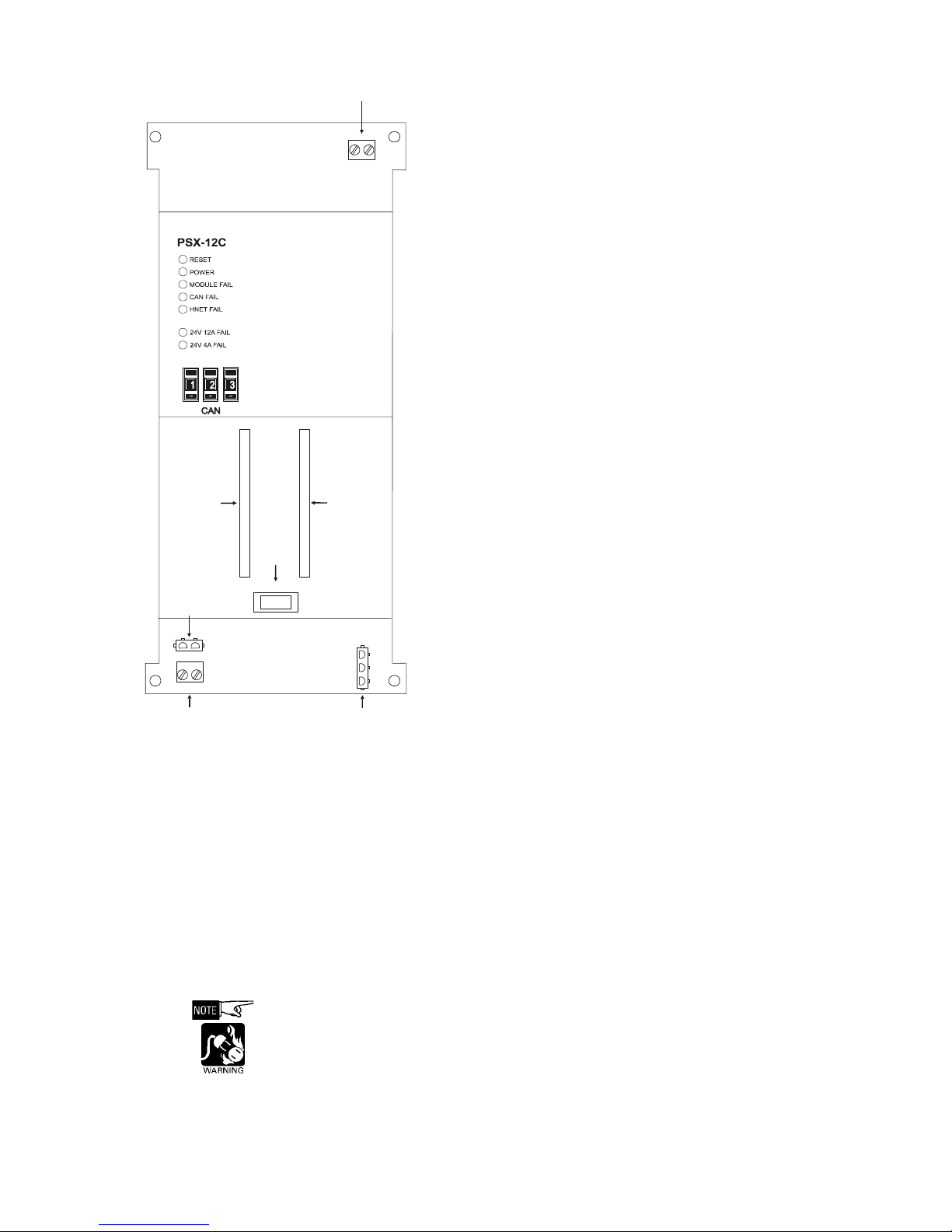
Terminal Blocks, The PSX-12C has one reset switch, six LEDs, one address switch, one circuit breaker,
two terminal blocks, two terminal connections and two 60 pin flat ribbon connections
as shown in Figure 2.The ribbon cable connectors are used to connect the PSX-12C
with a PSC-12C, additional PSX-12-Cs or a Card Cage (CC-2/CC-5).
A reset switch is located on the top of the front panel. Pushing the reset switch re-
initializes the PSX-12C operation.
The LEDs located at the top left of the module and are defined as follows:
POWER - (Green) Normally ON. When illuminated, indicates
that the PSX-12C is powered from the AC
mains. When flashing, indicates that the
PSX-12C is powered from the battery.
MODULE FAIL - (Yellow) Normally OFF. When illuminated indicates
that the module microprocessor has failed.
CAN FAIL - (Yellow) Normally OFF. When illuminated, indi-
cates that CAN communication with the
PSX-12C has terminated.
HNET FAIL - (Yellow) Normally OFF. Not used for E100
applications
Controls and Indicators

A24205-A334-B818
P/N 315-035840-1
3
24V 12A FAIL -(Yellow) Normally OFF. When illuminated, indicates
that the 24VDC non-power limited output
has a trouble condition or the PSX-12C
has disconnected the 24VDC output due
to current overload or short circuit.
24V 4A FAIL -(Yellow) Normally OFF. When illuminated, indi-
cates that the 24VDC power limited
output has a trouble condition or the
PSX-12C has disconnected the 24VDC
power output due to current overload or
short circuit.
The terminal blocks of the PSX-12C are defined as follows (refer to
Figure 2):
TB3 24VDC Power Limited OutputTerminal.This terminal
output is limited to 4A. When it is exceeded, it will shut
down, light its associated diagnostics LED and send a
fault condition to the PMI-S.
This output is normally connected to the modules and
cards located on the door of the enclosure or to the
remote CAN network modules.This output is power
limited to NFPA 70 per 760. All wiring must be in
accordance with Article 760 of NEC or local building
codes. (See Figure 2.)
Output Voltage: 24VDC +10%, -15%
Output Current: 4A max
TB3-1: (+) terminal
TB3-2: (-) terminal
TB4 24VDC Non-Power Limited Output Terminal.This
terminal is non-power limited and can supply up to 12A.
When the current draw is exceeded, it shuts down,
lights its associated LED and sends a fault condition to
the PMI-S.
This output is normally connected to the input terminals
of the CC-5. All wiring must be in accordance with
Article 760 of NEC or local building codes. (See Figure 2.)
Output Voltage: 24VDC +10%, -15%
Output Current: 12A max
TB4-1: (-) terminal
TB4-2: (+) terminal
The total cumulative sum of the 24VDC output (power limited + non-power limited)
must not exceed 12A. Over current draw will initiate a PSX-12C shut down.
The main AC power line must be turned OFF prior to installation.
Figure 2
Terminal Blocks, Controls
and Indicators
+ + +
1
1
+
+
+
_
_
_
2
2
L
N
GND
P9 P12
TB3
TB4
POWER LIMITED OUTPUT
(24VDC @ 4A)
AC
CONNECTION
(INPUT)
NON- POWER
LIMITED OUTPUT
(
24VDC @ 12A Max.)
BATTERY
CONNECTION
TO PSC-12C,
PSX-12C
OR CC-5/CC-2
TO PSC-12C,
PSX-12C
OR CC-5/CC-2
BATTERY
CIRCUIT
BREAKER
OFF
O —
ON

A24205-A334-B818
P/N 315-035840-1
4
P9 Connects the back-up battery to the PSX-12C.
Always apply AC power first followed by the battery.
P12 AC input connector
60-pin Connects the PSX-12C to the system. It is a straight- through connection
between the two connectors. It contains the communication signals and
system signal bus that is necessary for the proper operation of the
system.
These connectors are power limited. If the PSX-12C is located in a
different row in the enclosure, an optional extended ribbon cable,
SIEMENS Model FCL (C24200-K28-B6), must be used.
PRE-INSTALLATION The PSX-12C installation kit has the following components:
The following part is optional:
• If the PSX-12C is not located on the same CAB-MP as the PSC-12C, PSX-12C
and/or CC-5/CC-2 it is connected to, an extended 60 pin flat ribbon cable,
SIEMENS Model FCL (C24200-K28-B6)), is required.
The following components must be set prior installing the module in the enclosure:
Verify that the dedicated circuit breaker for the PSX-12-C is turned OFF at the mains.
•Battery Circuit Breaker: Set this circuit breaker to the OFF position.
•Network Address Switch: Set the three-digit CAN network address for the
PSX-12C using the three-position switch located near the bottom of the
front panel. (Refer to Figure 2 for the location of the switch.) The address for
the PSX-12C must be the same as the address selected for it in the Zeus
Programming Tool.To increment each digit of the address, press the “+”
button above the desired digit; to decrement each digit, press the “-” button
below the desired digit. The range of allowable addresses is from 001 to
251 (leading zeros must be used).
STNENOPMOCTIKNOITALLATSNI
elbac-rewopCA17B-01K-00242C
eulb/dereriwCD16B-01K-00242C
mm561=l,sniP06elbacnobbiR111640000Q5A
swercsdaehta
lF485930000Q5A
rehsawtcatnoC1766S-05A-39007H

A24205-A334-B818
P/N 315-035840-1
5
INSTALLATION
Disconnect BATTERY and AC
prior to working on equipment.
The PSX-12C mounts on the
Mounting Plate (CAB-MP).The
Mounting Plate may be located
either “IN” or “OUT” of the
enclosure to perform this
installation procedure. If the
Mounting Plate is located “IN”
the enclosure you will have to
gain access to it by opening the
enclosure Inner and Outer
doors. If the Mounting Plate is
located outside of the enclo-
sure, place it in front of you so
that the word “TOP” is at the
top and away from you.
The PSX-12C can occupy any
position on the mounting plate,
but it should be installed in the
row and position that is located
directly above the PTB to
which it is connected. (Refer to
Figures 3 and 5). When the
PSX-12C is mounted correctly
on the Mounting Plate it will be
flush on the top, bottom, and
right with the Mounting Plate
and the mounting screw holes
of the PSX-12C will align with
the threaded posts.
1. Install four M5 screws in
the threaded posts at the
mounting position. Screw
each of the M5 screws
into the threaded posts 5-6
turns.
2. Place the PSX-12C over
the four screws on the
Mounting Plate and slide it
down or towards you to
rest on the four screws.
(Refer to Figure 4.) When the PSX-12C is in the correct position it will be flush
with the top, bottom and right side of the Mounting Plate.
3. Tighten the four screws.
Figure 3
Location Of The PSX-12C On The MP-M
Figure 4
Mounting The PSX-12C On The MP-M
T
,
RIGHTOM
CAB-MP
PSC-12
PSX-12C
MOUNTING PLATE MP-M
SLIDE DOWN UNTIL
FLUSH ON TOP,
RIGHT, AND BOTTO
M

A24205-A334-B818
P/N 315-035840-1
6
WIRING The PSX-12C has removable terminal blocks and connectors at the top and bottom of
the module. The terminal block at the top of the PSX-12C is power limited.The
terminals and connectors at the bottom of the PSX-12C are non-power limited. (Refer
to Figure 5.)
Use a separate or dedicated circuit breaker and run the earth ground from a suitable
source to the PSX-12C. Check local requirements.
Conduit is not an acceptable Earth Ground Conductor.
Wire in accordance with local codes.
Figure 5
PSX-12C Wiring In The CAB Enclosures
Battery
PSC-12CPSX-12C
RESETRESET
POWERPOWER
MODU LE FAILMODULE FAIL
H - NET FAILH - NET FA IL
GND FAULTGND FAULT 24V 12 FAIL24V12 FAIL
24V 4AFAIL24V 4A FAIL
CAN FAILCAN FAIL
TB3TB3 P4 TB1
P5
TB2
CC-5
CC-5
CC-5
Power Limited Wiring
Non-Power Limited Wiring
1
+
+
_
_
2H
N
GND
P9 P12
TB4
BATTERY
OFF
O —
ON
BATTERY
OFF
O —
ON
1
+
+
_
_
2H
N
GND
P9 P12
TB4
TO AC MAINS

A24205-A334-B818
P/N 315-035840-1
7
Figure 6
Wiring In The CAB-2 Enclosure
PSX-12C
RESET
POWER
MODULE FAIL
H - NET FAIL
GND FAULT
24V 12 FAIL
24V 4A FAIL
CAN FAIL
TB3
1
+_
2
TB4
L
N
GND
P12
+
_
P9
PSC-12C
RESET
POWER
MODULE FAIL
H - NET FAIL
GND FAULT
24V 12 FAIL
24V 4AFAIL
CAN FAIL
TB3
P4 TB1
P5
TB2
1
+_
2
TB4
L
N
GND
P12
+
_
P9
gnye gnye
bk bk
blbl
0,75 mm
2
P9
-+
P9
-+
24V/12A R1
R2
R4
R3
gnye
bk bl
bl
br
gnye
230VAC
50 ... 60Hz
BATTERY
OFF
O —
ON
BATTERY
OFF
O —
ON

A24205-A334-B818
P/N 315-035840-1
8
PSX-12C
RESET
POWER
MODULE FAIL
H - NET FAIL
GND FAULT
24V 12 FAIL
24V 4A FAIL
CAN FAIL
TB3
1
+_
2
TB4
L
N
GND
P12
+
_
P9
PSC-12C
RESET
POWER
MODULE FAIL
H - NET FAIL
GND FAULT
24V 12 FAIL
24V 4AFAIL
CAN FAIL
TB3
P4
TB1
P5
TB2
1
+_
2
TB4
L
N
GND
P12
+
_
P9
gnye gnye
bk bk
bl
bl
gnye
gnye
bk bk
bk
bl bl
bl
0,75 mm
2
P9
-
+
P9
-
+
24V/12A R1
R2
R4
R3
bl
gnye
br
230VAC
50 ... 60Hz
BATTERY
OFF
O —
ON
BATTERY
OFF
O —
ON
Figure 7
Wiring In The CAB-19 Enclosure

A24205-A334-B818
P/N 315-035840-1
9
Power Supply Load Calculations
To ensure that the PSX-12C power supply is not overloaded, use the form and follow
the procedure listed below.
1. Enter the quantity of each card/module in the enclosure.
2. Calculate both the 24VDC and 6.2VDC loads for each row.
3. Total the Active 24VDC and Active 6.2VDC columns.
4. Ensure that both totals are within the power supply output ratings.
MROFNOITALUCLACDAOLYLPPUSREWOP
/draC eludoM ytitnauQ tnerruCV42lanimreTwercS
eludoM/draCreP CDV42latoT tnerruC
CIA00
TEN-CAD00
S6-MCF +Am41 DELevit
carepAm1
S-TMFAm051
S8-MCL +Am41 DELevitcarepAm1
BPL00
SH/SS-MVLAm52
D-MVLAm001
C-CIN00
61-MCO +Am41 DELevitcarepAm01
IM
P00
INRAm57
MPRAm051
S8-MCS +Am41 DELevitcarepAm1
61-MIS +yalerevitcarepAm01 tupni.vpusrepAm2.1
B8-CZTAm553
04-CAZ +A
m051 ttaWrepAm35
081-MAZ +Am082 ttaWrepAm35
CA4-CIZtnadnepedegasU
tontsuM( 21deecxe )spmA

Figure 8
Wiring Batteries
Battery Power Make sure that the battery circuit breaker is in the OFF position.
Use either 14 or 12 AWG for (2.5mm2or 4mm2 ) battery connection.
Battery backup is required. (15 amp hours is the minimum size and 100 amp hours is
the maximum size of the battery for the PSX-12C).
Battery Connections
1. Attach the red battery wire to the quick disconnect on the positive terminal
and the blue battery wire to the quick disconnect on the negative terminal
with the M5 screws and lock nuts supplied with the PSC-12C.
2. Close the covers of the battery terminals.
A24205-A334-B818
P/N 315-035840-1
10

PSX-12C
RESET
POWER
MODULE FAIL
H - NET FAIL
GND FAULT
24V12 FAIL
24V 4A FAIL
CAN FAIL
TB3
BATTERY
1
+
_
2
TB4
L
N
GND
P12
+
_
P9
2
,5 mm
2
PSX-12C
RESET
P
OWER
M
ODULE FAIL
H - NET FAIL
G
NDFAULT
2
4V 12 FAIL
2
4V 4A FAIL
CAN FAIL
TB3
BATTERY
1
+
_
2
TB4
L
N
G
ND
P12
+
_
P9
PSC-12C
RESET
POWE R
MODULE FAIL
H - NET FAIL
GND FAULT
24V 12 FAIL
24V 4A FAIL
CAN FAIL
TB3
P4 TB1
P5
BATTERY
TB2
1
+
_
2
TB4
L
N
GND
P12
+
_
P9
PSX-12C
RESET
POWER
MODULE FAIL
H - NET FAIL
GND FAULT
24V 12 FAIL
24V4A FAIL
CAN FAIL
TB3
BATTERY
1
+
_
2
TB4
L
N
GND
P12
+
_
P9
PSC-12C
RESET
POWER
MODULE FAIL
H - NET FAIL
GND FAULT
24V 12 FAIL
24V 4A FAIL
CAN FAIL
TB3
P4 TB1
P5
BATTERY
TB2
1
+
_
2
TB4
L
N
GND
P12
+
_
P9
P9
-+
PSX-12C
RESET
P
OWE R
M
ODULE FAIL
H - NET FAIL
G
ND FAULT
2
4V 12FAIL
2
4V 4A FAIL
CAN FAIL
TB3
BATTERY
1
+
_
2
TB4
H
N
G
ND
P12
+
_
P9
PSC-12C
RESET
P
OWER
M
ODULE FAIL
H - NET FAIL
G
ND FAULT
2
4V 12 FAIL
2
4V 4A FAI L
CAN FAIL
TB3
P4
TB1
P5
BATTERY
TB2
1
+
_
2
TB4
L
N
G
ND
P12
+
_
P9
P9
-+
P9
-+
BATTERY
OFF
O —
ON
BATTERY
OFF
O —
ON
P9
-+
OFF
O —
ON
BATTERY
OFF
O —
ON
B
ATTERY
OFF
O —
ON
B
ATTERY
P9
-+
OFF
O —
ON
BATTERY
P9
-+
A24205-A334-B818
P/N 315-035840-1
11
Figure 9
Wiring Batteries To The PSX-12C

For CE applications in Cerberus E100 systems refer to
Installation Instruction A24205-A334-B844 (English) or A24205-A334-A844 (German).
ELECTRICAL RATINGS
egatloVtupnI CAV042/CAV022/CAV021 %51-,%01+
tnerruCtupnI CAV021@.xaMA3.3 CAV022@.xaMA5.2 CAV042@.xaMA0.2
tne
rruCV42lanimreTwercS .xaMA4:detimiLrewoP
.
xaMA21:detimiLrewoP-noN
tnerruCybdnatSV42Am051
Order No. A24205-A334-B818
(Edition1)
P/N 315-035840-1
© Siemens Gebäudesicherheit GmbH & Co. oHG 2003
Siemens Building Technologies, Inc. Florham Park, New Jersey 07932
Siemens Building Technologies, Ltd Brampton, Ontario L6T 5E4 CN
Issued by Siemens
Gebäudesicherheit Gmbh & Co. oHG
D-80930 München
Delivery subject to availability;
right of technical modifications reserved.
Table of contents
Other Siemens Extender manuals

Siemens
Siemens PAD-4 User manual

Siemens
Siemens SPCW130 User manual

Siemens
Siemens SIMATIC NET SCALANCE XM-400 User manual

Siemens
Siemens SPCE120 User manual

Siemens
Siemens 505-2571 User manual

Siemens
Siemens PAD-3 User manual

Siemens
Siemens 6ES7 972-4AA02-0XA0 User manual

Siemens
Siemens SIMATIC User manual

Siemens
Siemens SPCE450 User manual

Siemens
Siemens SIMATIC NET PE408 User manual