Siemens LOGO! User manual

52,4
90
1
1
1
71,5
P1 P2 P3
2
P1
AC/DC
230V
P2 P3 P4
L1 N
X1:P4
X1:P1 X1:P2 X1:P3
X10
1
1
3
6GK7177-1FA10-0AA0
s
LOGO! CSM2 30
DC 115...210V 0.02...0.01A
AC 100...240V ~ 0.02...0.01A
X1:P1 TO X1:P4 FOR LAN ONLY
Mounting slides Hole pattern for wall mounting
Prior to wall-mounting, the mounting slides on the back
of the device are pushed open.
98 +/- 0.3
1
2
P1
AC/DC
230V
P2 P3 P4
X1:P4
X1:P1 X1:P2 X1:P3
L- N
36.0
cULus
C-Tick
- UL 508 Listed
- CSA C22.2 Number 142
AS/NZS 2064 Class A
cULus Haz.Loc.
FM
You can use the device in the following hazardous locations:
IND. CONT. EQ., E223122, UL 1604, UL 2279-15
FM3600 and 3611:
CL. I, Div. 2, Group A, B, C, D, T4
CL. I, Zone 2, Group IIC, T4, Ta = 55°C
Installation, Connection, Technical specifications
2
3
1
EU Directive 2004/108/EC "Electromagnetic Compatibility" (EMC Directive)
- Emission: EN 55022 Class B: 2010
- Immunity: EN 61000-6-2: 2005
EU Directive 2006/95/EC "Low Voltage Directive" (LVD)
- Safety: EN 61131-2: 2008
The EC Declaration of Conformity is available for all responsible authorities at:
Siemens Aktiengesellschaft
Industry Automation, I IA SC CI
Postfach 4848
D-90026 Nuernberg
Germany
You will find the EC Declaration of Conformity for this product on the Internet
at the following address:
http://support.automation.siemens.com/WW/view/en/10805878
→ Tab "Entry List"
Filter settings: Entry type: "Certificates"
Certificate Type: "Declaration of Conformity"
Search items(s): <name of the module>
The product meets the requirements and aims of the following EC directives:
Sources of information and other documentation
The "SIMATIC NET Industrial Ethernet Network Manual" contains
detailed information on the network structure, maximum cable lengths,
cabling technology etc.
http://support.automation.siemens.com/WW/view/en/27069465
Entry ID: 27069465
You will find additional information on the Siemens LOGO! Web page:
http://www.siemens.com/logo
Neutral C onductorN
ConductorL1
Functional grounding
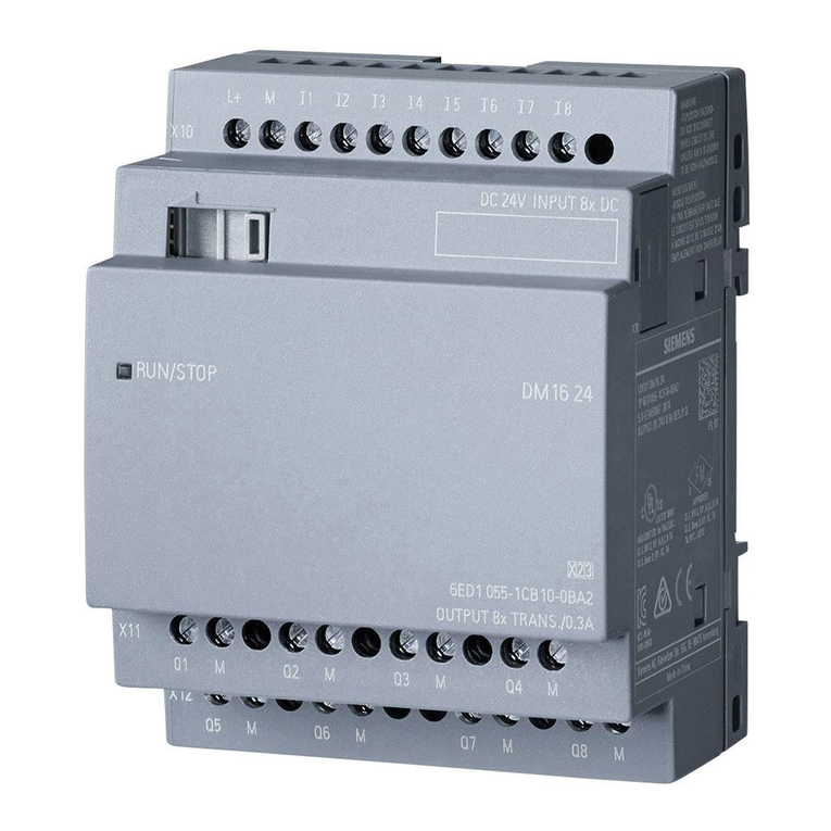
RJ-45 jacks for connections via Ethernet (10/100 Mbps)
LED for the power supply (AC/DC 230V) and
LEDs for the Ethernet communication status (P1 - P4)
Three screw terminals:
AC 47... 63 HzPermitted line power frequency
Technical specifications
All ports adhere to 1.5 kV insulation voltage:
- to shield
- between the ports.
Insulation of the ports
Ethernet interface
300 seconds
Aging Time
1024
Functional grounding can be established by connecting a cable
from terminal 3, for example to the DIN rail. Such a cable should be
kept as short as possible. Grounding is, however, not necessary for
interference-free operation.
Functional grounding
Per terminal for L1 and N
Cable cross section: 1 x 2.5 mm2 or 2 x 1.5 mm2
Connection
1.8 WEffective power loss
- AC 100 ... 240 V: 0.05 ... 0.03 A
- DC 115 ... 210 V: 0.02 ... 0.012 A
Current consumption (I)
AC 100 ... 240 V
DC 115 ... 210 V
Input voltage
Electrical specification
Delay resulting from latency
64 byteSmallest data packet
1518 byteLargest data packet
A standard Ethernet cable can be connected to the Ethernet interface.
However, to minimize electromagnetic interference, Siemens
recommends a shielded Ethernet cable with a twisted pair
(category 5) with a shielded RJ-45 connector at both ends.
Network cable
4 x RJ‑45 jacks with MDI‑X assignment 10/100 Mbps
(half / full duplex), autopolarity, autonegotiation
Communications connector
Star and bus topology
Note that the direct connection of two ports on the switch or
accidental connection over several switches causes an illegal loop.
Such a loop can lead to network overload and network failures.
Topology
When a frame passes through the CSM 230, it is delayed
by the store and forward function of the switch:
- with a 64 byte frame length by approx. 8 μs (at 100 Mbps).
- with a 1518 byte frame length by approx. 125 μs (at 100 Mbps).
Technical specifications
You will find the currently valid approvals on the type plate.
Approvals
http://www.siemens.com/logo
When installing and connecting up, keep to the procedures described in the LOGO! manual.
You will find additional information on the Siemens LOGO! web page:
Entry ID: 50074616
http://support.automation.siemens.com/WW/view/en/50074616
Entry ID: 27069465
http://support.automation.siemens.com/WW/view/en/27069465
Sources of information and other documentation
Prior to installation, connecting up and commissioning, read the relevant sections
in the LOGO! manual:
Installation
Order number: 6GK7177-1FA10-0AA0
Status of LEDs
Product information
© Siemens AG 2012
A5E03733191-04
CSM 230
LOGO!
MeaningStatusLED
P1 - P4
P1 - P4
LOGO! receives / sends data via Ethernet.
Power is connected.
The connection via Ethernet is established (link up).
No connection via Ethernet (link down).
Power is not connected or the connected
power is too low.
Off
Off
Flashing
On
On
AC/DC
230V
AC/DC
230V
P1 - P4
IP 20Degree of protection
35 mm DIN rail (DIN EN 60715 TH35) or wall mountingInstallation
Net weight 155 g
72 (4 TE) x 90 x 55 mmDimensions (W x H x D) in mm
< 90% (no condensation)Relative humidity during operation
- 40°C … +70°CTransport/storage temperature
0 … 55°C
Operating temperature
Further technical specifications
Learnable MAC addresses
DIN rail mount
2. Press down the lower part until the device locks in place.
The mounting slide on the back must snap into place.
1. Fit the LOGO! onto the DIN rail.
Pin 8 - n. c.
Pin 7 - n. c.
Pin 6 - TD -
Pin 5 - n. c.
Pin 4 - n. c.
Pin 3 - TD +
Pin 2 - RD -
Pin 1 - RD +
RJ-45 jacks with MDI-X assignment
Wall mounting
All dimensions in mm
Tightening torque 0.8 ... 1.2 Nm
Hole for screw Ø 4 mm
The "SIMATIC NET Industrial Ether net Networking Manual" cont ains detailed information
on the network structure, maximum cable lengths, cabling technology etc.
To fulfill the requirements according radiated emission EN 55022 Class B, the shield of all
connected LAN cables must be grounded.
Release 06/2012

警告
机柜/机壳要求
在相当于 I 级 2 分区或 I 级 2 区的危险环境下使用本设备时,必须将其安装在机柜或适当的机壳内。
更换组件
更换组件可能损害在 I 级 2 分区或 2 区的适用性。
连接或断开本设备时有爆炸风险
请勿在易燃环境下连接或断开设备。
警告 - 爆炸危险
LOGO! 模块是开放式设备。 也就是说,LOGO! 必须安装在外罩或者机柜中。
在 LOGO! 使用手册中有详细说明。
警告
只有正确地运输、存储、设置和安装本产品,并且按照推荐的方式操作和维护,产品才能正常、安全地运行。
只能让电气专业人员执行连接和断开操作。
只能在电源已关闭的情况下连接或断开电源电缆。
危险
有关在危险场所使用的通用注意事项
警告 - 爆炸危险
重要事项
说明
始终确保 LOGO! 的接线符合当前的规定和标准。 并且确保设备的安装和操作符合国家和
地区的所有规定。 请联系本地机构了解您具体情况下应遵守的标准和规章。
Attention
Exigences relatives à l'armoire électrique
En cas d'utilisation en atmosphère explosible selon Class I, Division 2 ou Class 1,
Zone 2, l'appareil doit être incorporé à une armoire électrique ou à un boîtier.
Echange de composants
L'échange de composants peut porter préjudice à la conformité à Class I, Division 2
ou Zone 2.
Danger d'explosion lors de la connexion ou déconnexion de l'appareil
II est interdit, dans un environnement facilement inflammable ou combustible, de
connecter des câbles à l'appareil ou de les déconnecter.
Attention - Danger l'explosion
Les modules de LOGO! sont des équipements ouverts. Cela signifie que que vous
devez installer LOGO! uniquement dans un boîtier ou une armoire.
Vous trouverez davantage d’informations dans le manuel de LOGO!
Attention
Un transport, un stockage, une installation et un montage en bonne et due forme ainsi
qu'une manipulation et un entretien effectués avec soin sont des conditions préalables
essentielles pour que le matériel puisse fonctionner parfaitement et en toute sécurité.
Seul un électricien qualifié est autorisé à effectuer le branchement/débranchement ! Il
est interdit de brancher ou de débrancher des câbles d'alimentation sous tension.
Danger
Consignes pour une mise en oeuvre en atmosphère explosible
Remarques importantes
Assurez-vous toujours que le câblage de votre LOGO! est conforme aux règles et
normes en vigueur. Lors de l'installation et de l'utilisation des appareils, respectez
également les réglementations nationales et régionales. Consultez les administrations
locales pour savoir quelles normes et réglementations doivent être appliquées dans
votre cas particulier.
Remarque
Attention - Danger l'explosion
Avvertenza
Requisiti richiesti per il quadro elettrico
In caso di impiego in ambiente a rischio di esplosione secondo la Class I, Division 2
o Class I, Zone 2, l'apparecchio deve essere montato in un quadro elettrico o in una
custodia.
Sostituzione di componenti
La sostituzione di componenti può compromettere l'idoneità per Dlass I, Division 2
o Zone 2.
Pericolo di esplosione durante il collegamento o la rimozione dell'apparecchio
In un ambiente facilmente infiammabile o incendiabile non devono essere collegati
o scollegati cavi dall'apparecchio.
Avvertenza - Pericolo di esplosione
I moduli LOGO! sono dispositivi elettrici aperti e vanno pertanto installati in un case o
un armadio. Ulteriori informazioni si trovano nel manuale di LOGO!
Avvertenza
Il funzionamento coretto e sicuro del prodotto presuppone un trasporto, un
magazzinaggio, un'installazione e un montaggio appropriati nonché un comando e
una manutenzione accurati. Il collegamento/la rimozione possono essere eseguiti
solo da personale elettrico specializzato! I cavi per l'alimentazione possono essere
collegati o rimossi solo in assenza di tensione.
Pericolo
Avvertenze per l'impiego in zone Ex
Avvertenze importanti
Accertarsi sempre che il cablaggio di LOGO! sia conforme alle regole e alle norme
correnti. Durante l'installazione e l'uso dei dispositivi attenersi alle norme nazionali e
regionali vigenti. Per informazioni sulle norme e le prescrizioni applicabili al proprio
caso specifico rivolgersi agli enti locali preposti.
Nota
Avvertenza - Pericolo di esplosione
Advertencia
Requisitos exigidos al armario de distribución
Para el uso en atmósferas potencialmente explosivas según Class I, Division 2 o Class I,
Zone 2, el aparato se tiene que montar en un armario de distribución o en una carcasa.
Sustitución de componentes
La sustitución de componentes puede mermar la aptitud para la Class I, Division 2 o
Zone 2.
Riesgo de explosión al conectar o desconectar el aparato
En una atmósfera fácilmente inflamable o combustible no se deben conectar cables al
aparato ni desconectarlos del mismo.
Advertencia - Riesgo de explosión
Los módulos LOGO! son material eléctrico abierto. Por tanto, LOGO! debe montarse en
una carcasa o armario eléctrico.
Encontrarán más informaciones en el manual sobre LOGO!
Advertencia
El funcionamiento correcto y seguro del producto presupone que se realicen correcta-
mente el transporte, el almacenamiento, la instalación y el montaje así como un manejo
y un mantenimiento esmerados. Las operaciones de conexión y desconexión deben ser
realizadas sólo por electricistas profesionales. Los cables de alimentación de tensión se
deben conectar o desconectar sólo en estado sin tensión.
Peligro
Indicaciones para el uso en la zona Ex
Indicaciones importantes
Vigile siempre que el cableado del LOGO! cumpla todas las reglas y normas vigentes.
Observe asimismo todos los reglamentos nacionales y regionales durante el montaje y
la operación de los dispositivos. Para más información sobre las normas y reglamentos
aplicables a su caso específico, contacte con las autoridades locales.
Nota
Advertencia - Riesgo de explosión
Warnung
Anforderungen an den Schaltschrank
Bei Einsatz in explosionsgefährdeter Umgebung entsprechend Class I, Division 2 oder
Class I, Zone 2 muss das Gerät in einen Schaltschrank oder in ein Gehäuse eingebaut
werden.
Austausch von Komponenten
Der Austausch von Komponenten kann die Eignung für Class I, Division 2 oder Zone 2
beeinträchtigen.
Explosionsgefahr beim Anschließen oder Abklemmen des Geräts
In einer leicht entzündlichen oder brennbaren Umgebung dürfen keine Leitungen
an das Gerät angeschlossen oder vom Gerät getrennt werden.
Warnung - Explorsionsgefahr
Baugruppen einer LOGO! sind offene Betriebsmittel. Das heißt, Sie dürfen LOGO! nur
in Gehäuse oder Schränke einbauen.
Weitere Informationen finden Sie im Handbuch zu LOGO!
Warnung
Der einwandfreie und sichere Betrieb des Produkts setzt sachgemäßen Transport,
sachgemäße Lagerung, Aufstellung und Montage sowie sorgfältige Bedienung und
Instandhaltung voraus. Das Anschließen/Abklemmen darf nur von einer Elektrofachkraft
durchgeführt werden! Leitungen für die Spannungsversorgung dürfen nur in spannungs-
losem Zustand angeschlossen oder abgeklemmt werden.
Gefahr
Hinweise für den Einsatz im Ex-Bereich
Wichtige Hinweise
Stellen Sie sicher, dass Sie bei der Verdrahtung Ihrer LOGO! alle geltenden und
verbindlichen Richtlinien und Normen befolgen. Beachten Sie bei Installation und Betrieb
der Geräte die entsprechenden nationalen und regionalen Vorschriften. Erfragen Sie bei
den Behörden vor Ort die Normen und Vorschriften, die für Ihren speziellen Fall zu
befolgen sind.
Hinweis
Warnung - Explorsionsgefahr
Warning
Requirements for the cabinet/enclosure
When used in hazardous areas corresponding to Class I, Division 2 or
Class I, Zone 2, the device must be installed in a cabinet or a suitable
enclosure.
Warning - Explosion hazard
Replacing components
Replacing components may impair suitability for class I, division 2 or
zone 2.
Warning - Explosion hazard
Risk of explosion when connecting or disconnecting the device
Do not connect or disconnect equipment when a flammable or
combustible atmosphere is present.
Warning
Modules of a LOGO! are open equipment. This means that you must
install LOGO! only in an enclosure or cabinet. You will find more
detailed information in the LOGO! manual.
Danger
This product can only function correctly and safely if it is transported,
stored, set up, and installed correctly, and operated and maintained as
recommended. Connecting and disconnecting may only be performed
by an electrical specialist. Connect or disconnect power supply cables
only when the power is turned off!
Notices regarding use in hazardous areas
Important notes
Notice
Always ensure that the wiring of your LOGO! is compliant with current
rules and standards. Also, conform with all national and regional
regulations when you install and operate the devices. For information
on standards and regulations that apply to your specific case, contact
your local authorities.
Other manuals for LOGO!
3
This manual suits for next models
1
Other Siemens Microcontroller manuals
Popular Microcontroller manuals by other brands

Novatek
Novatek NT6861 manual

Espressif Systems
Espressif Systems ESP8266 SDK AT Instruction Set

Nuvoton
Nuvoton ISD61S00 ChipCorder Design guide

STMicrolectronics
STMicrolectronics ST7 Assembler Linker user manual

Texas Instruments
Texas Instruments Chipcon CC2420DK user manual

Lantronix
Lantronix Intrinsyc Open-Q 865XR SOM user guide
