Siemens AG
Siemensstr. 10
D - 93055 Regensburg
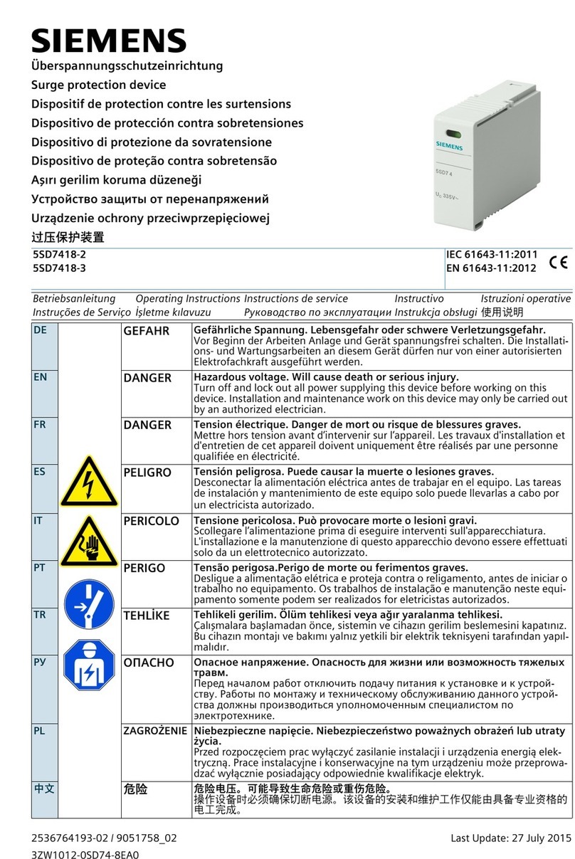
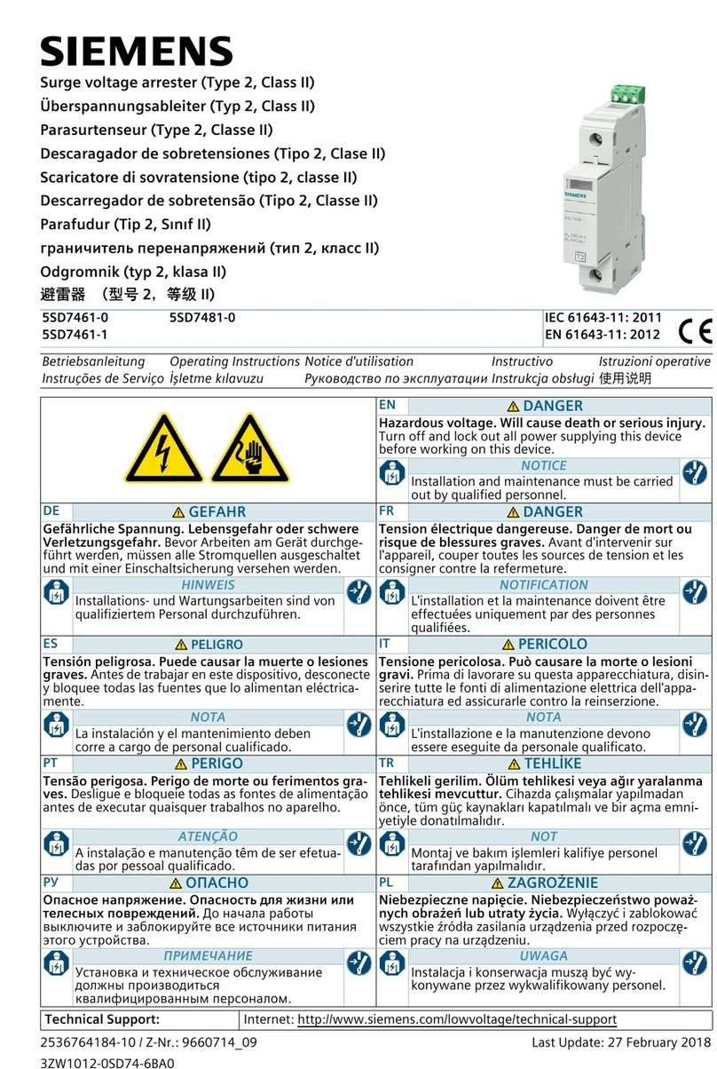
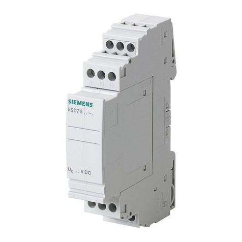
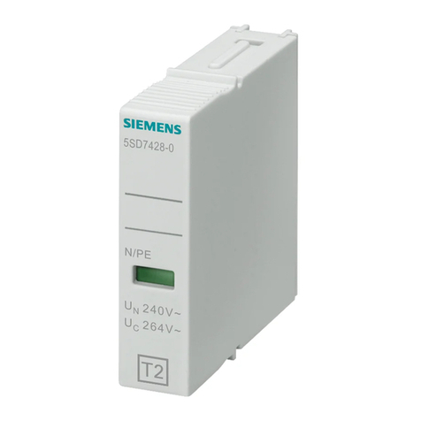
5SD7 413-2 und 5SD7 413-3 sind Blitzstromableitern mit steckbaren Schutzmodulen
5SD7 418-3 auf Varistorbasis.
Der Anschluss und die Montage des Gerätes darf nur durch eine Elektrofachkraft
erfolgen. Die nationalen Vorschriften und Sicherheitsbestimmungen sind zu beachten
(siehe auch DIN VDE 0100-534... bzw. IEC 60364-5 53...).
Zudem sind landesspezifische Vorschriften und Gesetze einzuhalten.
Der Einsatz des Gerätes ist nur im Rahmen der in dieser Einbauanleitung genannten und
gezeigten Bedingungen zulässig. Bei Belastungen, die über den ausgewiesenen Werten
liegen, können das Gerät sowie die daran angeschlossenen elektrischen Betriebsmittel
zerstört werden.
Bei Öffnen des Gerätes erlischt der Gewährleistungsanspruch gegenüber dem Her-
steller.
Isolationsmessungen
Ziehen Sie vor einer Isolationsmessung in der Anlage den Schutzstecker. Andernfalls
sind Fehlmessungen möglich. Setzen Sie den Stecker nach der Isolationsmessung
wieder in das Basiselement ein.
DE
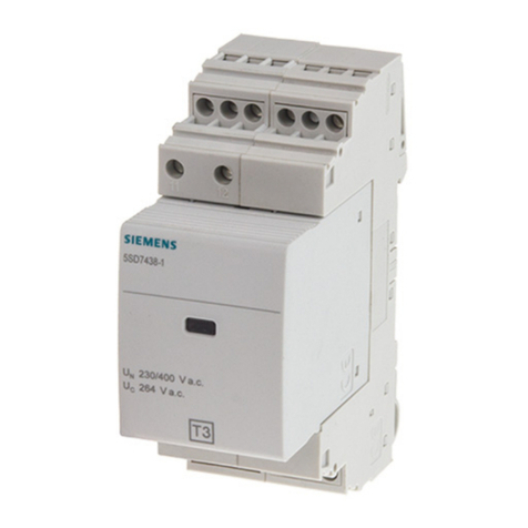
The 5SD7 413-2 and 5SD7 413-3 are lightning arresters with pluggable 5SD7 418-3
protection modules on varistor basis.
The device may only be connected and installed by a qualified electrician. The national
rules and safety regulations must be observed (see also DIN VDE 0100-534... or
IEC 60364-5 53...).
Country-specific regulations and laws must also be observed.
The device may only be used under the conditions shown and referred to in these
installation instructions. Loads above the values indicated can lead to the destruction of
the device and the electrical equipment connected.
The manufacturer's warranty no longer applies if the device is opened.
Insulation measurements
Unplug the protective plug before performing an insulation measurement in the system.
Otherwise inaccurate measurements are possible. Re-insert the plug into the base
element after the insulation measurement.
EN
5SD7 413-2 et 5SD7 413-3 sont des parafoudres à module de protection enfichable
5SD7 418-3 équipé d'une varistance.
Seul un électricien a le droit de procéder au raccordement et au montage du module.
Les normes et contraintes de sécurité nationales doivent être respectées (voir aussi DIN
VDE 0100-534... et CEI 60364-5 53...).
Les prescriptions et lois nationales doivent en outre être respectées.
L'utilisation de ce module n'est autorisée que selon les conditions indiquées et montrées
dans les présentes instructions de montage. En cas de charges dépassant les valeurs
indiquées, le module et le matériel électrique auquel il est raccordé peuvent être détruits.
Si le module est ouvert, le droit de garantie envers le constructeur sera annulé.
Mesures de l'isolement
Retirez la fiche de protection de l'installation avant d'effectuer une mesure de l'isolement.
Dans le cas contraire, des erreurs de mesure pourraient apparaître. Réinsérez la fiche
dans son embase après la mesure de l'isolement.
FR
5SD7 413-2 y 5SD7 413-3 son derivadores de corriente de rayos con módulos de pro-
tección conectables 5SD7 418-3 a base de varistores.
La conexión y el montaje del aparato sólo deben ser efectuados por un electricista.
Han de observarse las prescripciones y normas de seguridad nacionales (ver también
DIN VDE 0100-534... o IEC 60364-5 53...).
Además, deben observarse las normas y leyes específicas del país.
La utilización del aparato solo es admisible bajo las condiciones mencionadas y
mostradas en las presentes instrucciones de montaje. En caso de unas cargas superio-
res
a los valores indicados, tanto el aparato como los equipos eléctricos conectados al
mismo pueden quedar destruidos.
Al abrir el aparato se pierde cualquier derecho de garantía frente al fabricante.
Mediciones de aislamiento
Antes de realizar una medición de aislamiento en la instalación, desenchufe la pro-
tección enchufable. De lo contrario pueden producirse unas mediciones erróneas. Una
vez concluida la medición de aislamiento, vuelva a insertar la protección enchufable en
el elemento de base.
ES
5SD7 413-2 e 5SD7 413-3 sono scaricatori di corrente da fulmine con moduli di prote-
zione a innesto 5SD7 418-3 basati su varistori.
Il collegamento e il montaggio dell'apparecchiato possono essere effettuati solo da
tecnici specializzati, nel rispetto delle disposizioni e delle norme di sicurezza nazionali (v.
anche DIN VDE 0100-534... e IEC 60364-5 53...).
Devono inoltre essere osservate eventuali norme e regolamenti locali.
L'utilizzo dell'apparecchio è ammesso solo nelle condizioni specificate nelle presenti ist-
ruzioni. Eventuali carichi superiori ai valori indicati potrebbero distruggere l'apparecchio
e i dispositivi elettrici ad esso collegati.
La garanzia del produttore decade in caso di apertura dell'apparecchio.
Misurazioni dell'isolamento
Prima di una misurazione dell'isolamento nell'impianto, estrarre la spina di protezione,
per evitare possibili errori nelle misurazioni. Una volta conclusa la misurazione, reinserire
la spina nell'elemento di base.
IT
5SD7 413-2 e 5SD7 413-3 são protetores contra raios baseados em varistores com
módulos de proteção de encaixe 5SD7 418-3.
Apenas um técnico de electricidade está autorizado a efectuar a conexão e a montagem
do aparelho. É preciso respeitar as normas e as prescrições de segurança nacionais
(ver também DIN VDE 0100-534... e IEC 60364-5 53...).
Para além disso, é preciso respeitar as normas e leis específicas do país.
Só é permitido usar o aparelho de acordo com as condições mencionadas e indicadas
nestas instruções de montagem. Cargas superiores aos valores indicados podem pro-
vocar a destruição do aparelho e dos dispositivos eléctricos conectados a ele.
A garantia do fabricante perde a validade se o aparelho for aberto.
Medições do isolamento
Antes de efectuar uma medição do isolamento na instalação, retire a ficha de segu-
rança. Em caso contrário, medições incorrectas são possíveis. Após a realização da
medição do isolamento, introduza a ficha novamente no elemento de base.
PT
5SD7 413-2 и5SD7 413-3 - это варисторные грозозащитные разрядники со
вставными защитными модулями 5SD7 418-3.
Подключение имонтаж устройства должны проводить только
квалифицированные специалисты по электромонтажу. При монтаже соблюдайте
требования местных технических нормативных документов, атакже требования
по технике безопасности. (см. DIN VDE 0100-534... или МЭК 60364-5 53...).
Установку устройства следует проводить сучетом требований итехнических
условий, приведенных вданной инструкции. Превышение указанных предельных
значений нагрузки может привести кповреждению защитного устройства, а
также
подключенного кнему защищаемого оборудования.
При вскрытии корпуса изделия гарантия фирмы-изготовителя аннулируется.
Измерение сопротивления изоляции
Перед измерением сопротивления изоляции прибора снимите защитный штекер.
Впротивном случае измерения могут быть ошибочными. После измерения
изоляции установите штекерный модуль обратно на базовый элемент.
RU
5SD7 414-2 和 5SD7 414-3 雷电流避雷器附带基于可变电阻的可插接式保护模块
5SD7 418-3 以及一个封闭式无线插头 5SD7 418-2。
只允许由一位电器专家来进行设备的连接和安装。 必须遵守所在国家的安全法律规章和
规定 (参见 DIN VDE 0100-534… 和 IEC 60364-5 53… 规定)。
要遵守各个国家的相关要求和法律规定。
只有在此组装说明中叙述的并指出的允许条件下使用设备。超出规定数值的负荷可能引
起设备以及连接在设备上的电子运行装置出故障。
设备一旦打开,制造商的保险责任随即失效。
绝缘测量
在设备内进行绝缘测量时应先拔下保护插头。否则可能导致测量错误。完成绝缘测量后
将插头重新装入基座内。
ZH

