manuals.online logo
Brands
  1. Home
  2. •
  3. Brands
  4. •
  5. Siemens
  6. •
  7. Touch Terminal
  8. •
  9. Siemens SIDATA 9756 User manual

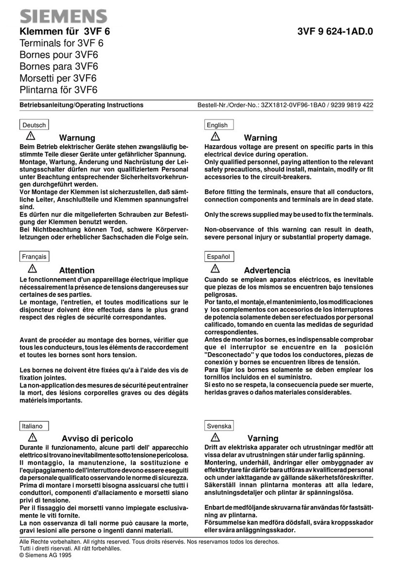
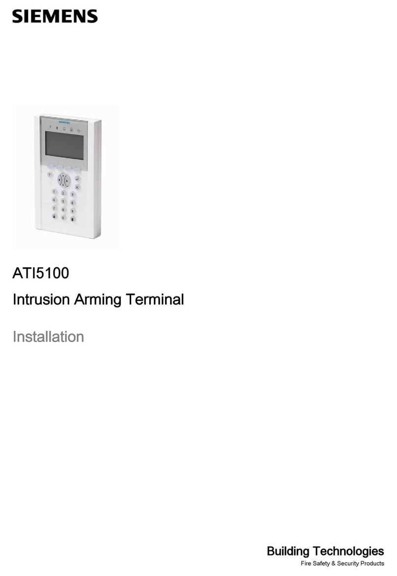
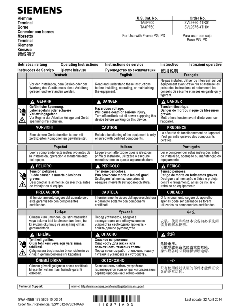
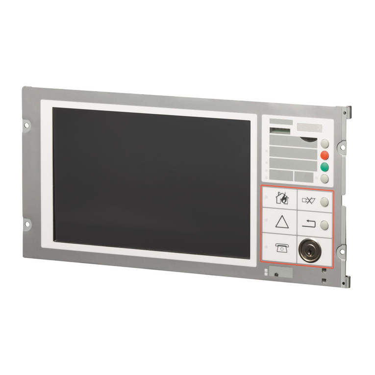
Siemens SIDATA 9756 User manual

SIEMENS
SIDATA
SIDATA
Datensichtstation
9756
Mehrfachstation
TRANSDATA®
Installationsanleitung
9756
Clustered
Data
Display
Terminal
Tl-‘lANSDATA®
Installation
Manual
SIDATA
Self
Installation
Dataprocessing
Datensiohtstation
9756
Mehrfachstation
Juli
1
987
Vervielfältigung
dieser
Unterlage
sowie
Venivertung
ihres
Inhalts
unzulässig,
soweit
nicht
ausdrücklich
zugestanden.
Im
Laufe
der
Entwicklung
des
Produktes
können
aus
technischen
oder
wirtschaftlichen
Gründen
Leistungsmerk-
male
hinzugefügt
bzw.
geändert
werden
oder
entfallen.
Ent-
sprechendes
gilt
für
andere
Angaben
in
dieser
Druckschrift.
Siemens
Aktiengesellschaft
SIDATA
Self
Installation
Dataprocessing
9756
Clustered
Data
Display
Terminal
July
1
987
This
document
shall
not
be
duplicated,
nor
its
contents
used
for
any
purpose,
unless
express
permission
has
been
granted.
Performance
features
may
be
added,
modified
or
omitted
in
the
course
of
product
development.
Other
information
in
this
publication
is
subject
to
the
same
conditions.
Siemens
Aktiengesellschaft
Inhalt
Hinweise
für
den
Benutzer
Folgende
Hinweiszeichen
sollen
Ihnen
den
Weg
durch
diese
Installationsanleitung
erleichtern:
El
Hier
müssen
Sie
etwas
tun.
.
Achtung;
diese
Angaben
sind
besonders
wichtig!
Q
Hinweis;
zusätzliche
Information.
Haben
Sie
Verbesserungsvorschläge
für
diese
Anlei-
tung,
bzw.
finden
Sie
etwas
unklar,
so
wenden
Sie
sich
bitte
an:
Siemens
AG
DOA
PM
Otto-Hahn-Ring
6
8000
München
83
Vorwort
Lieferung
überprüfen
.1
So
setzen
Sie
den
Monitor
auf
die
Steuereinheit
»
.2
Höhenverstellung
.3
So
verstellen
Sie
die
Bedienerebene
1
der
Tastatur
.4
Aufstellungshinweise
12
3
4
Datensichtstation
aufstellen
6
6
7
1
Datensichtstation
in
Betrieb
nehmen
14
.1
So
stecken
Sie
die
SIDATA*)-Module
14
.2
So
stellen
Sie
die
Offline-Anschlüsse
her
20
.3
In
Betrieb
nehmen
ohne
Rechneranschluß
27
(offline)
.4
So
stellen
Sie
den
Online-Anschluß
her
30
.5
In
Betrieb
nehmen
mit
Rechneranschluß
31
(online)
Betriebsparameter
einstellen
32
Was
tue
ich,
wenn
.
. .
49
Tests
aufrufen
51
Produktbegleitkarte
ausfüllen
52
So
machen
Sie
Ihr
Gerät
versandfertig
54
*)
Self
Installation
Dataprocessing
Contents
._L
ww
wwww N
NN
NM
01-b-
CON—L
CDNO'DU'l-P-
Notes
for
the
User
The
following
symbols
are
intended
to
assist
you
in
working
your
way
through
this
Installation
manual:
E]
User
action
required.
.
Important;
please
observe
with
particular
care!
Q
Note;
additional
information
of
relevance.
lf
you
have
suggestions
as
to
howthis
manual
might
be
improved,
0r
if
you
are
unclear
about
anything
it
con-
tains,
please
contact:
Siemens
AG
DOA
PM
Otto-Hahn-Ring
6
8000
München
83
lntroduction
Checking
the
delivery
consignment
—L
How
to
mount
the
monitor
on
the
control
unit
Height-adjustable
stand
How
to
alter
the
inclination
of
1
the
keyboard
Advice
on
positioning
the
terminal
12
3
4
Setting
up
the
data
display
terminal
6
6
7
1
JÄODN
Terminal
startup
14
How
to
install
the
SIDATA*)
modules
14
How
to
set
up
the
off-line
connections
20
Off-line
startup
procedure
27
On-line
connection
30
On-line
startup
procedure
31
Setting
the
operating
parameters
32
Having
problems?
49
Calling
up
tests
51
Filling
in
the
product
pass
52
How
to
prepare
your
terminal
for
return
54
shipment
Vorwort
Diese
Anleitung
zeigt
Ihnen,
wie
Sie
die
Datensicht-
station
9756
und
ihre
Varianten
9756-3,
-5
selbst
instal-
lieren
können.
Voraussetzung
für
eine
schnelle
Installation
ist,
daß
die
Vorarbeiten
entsprechend
der
TRANSDATA
Systemin-
stallation
(Bestell-Nr.
U1215-J-Z76-x),
Kapitel
2,
3
und
4,
ausgeführt
sind:
o
Der
Aufstellungsort
ist
entsprechend
vorbereitet,
o
geeignete
Möbel
zum
Aufstellen
der
Geräte
sind
vor-
handen,
o
die
Leitungen
für
Datenübertragung
und
Netzan-
schluß
sind
installiert,
o
die
umweltbedingungen
sind
überprüft
(KIima,Stör-
strahlung).
Nach
der
Inbetriebnahme
müssen
Sie
die
Produkt-
Zweigniederlassung
schicken.
Nur
so
werden
Sie
von
unserer
Wartungsabteilung
für
den
Service-Fall
registriert.
Siemens-Zweigniederlassung:
1
Lieferung
überprüfen
Die
Datensichtstation
wurde
auf
Vollständigkeit
über-
prüft
und
systemgetestet
ausgeliefert.
ß
Sollte
die
Lieferung
unvollständig
oder
defekt
bei
Ihnen
ankommen,
informieren
Sie
bitte
die
Siemens—
Niederlassung
oder
Ihren
Lieferanten.
Zur
vollständigen
Lieferung
gehören:
Tastatur,
Monitor,
Steuereinheit,
Netzkabel,
Koaxialkabel,
Datenleitung,
SIDATA-Module
(falls
bestellt)
Unterlagenbeipack,
bestehend
aus:
—-
Betriebsanleitung,
—
Installationsanleitung
und
—
Produktbegleitkarte.
Werfen
Sie
die
Verpackung
der
Datensichtstation
nicht
weg.
Sie
benötigen
sie
wieder
für
einen
eventu-
ellen
Rücktransport
(Kap.
8).
begleitkarte
(Kap.
7)
an
die
Sie
betreuende
Siemens-
Introduction
This
manual
describes
the
sequence
of
operations
necessary
for
installation
of
the
9756
Data
Display
Ter-
minal
and
its
versions
9756-3,
-5.
To
speed
up
the
installation
process,
the
user
should
carry
out
the
following
preparatory
measures,
as
laid
down
in
the
TRANSDATA
System
Installation
Manual
(Order
No.
U1215-J-Z76-x-7600),
sections
2,
3
and
4:
o
The
installation
site
must
be
properly
prepared.
0
Suitable
furniture
for
accommodating
the
equipment
must
be
provided.
0
The
data
communication
and
power
supply
lines
must
be
installed.
o
The
environmental
conditions
must
be
checked
in
advance
(air
conditioning,
radio
interference).
Having
put
your
data
display
terminal
into
operation,
'
pIease
remember
to
send
off
the
accompanying
pro-
.
duct
pass
to
your
local
Siemens
branch
office.
With-
out
it,
we
wiII
not
be
able
to
register
your
terminal
for
servicing
purposes.
Your
local
Siemens
office:
1
Checking
the
delivery
consignment
Prior
to
delivery,
your
data
display
terminal
was
fully
checked
out
and
subjected
to
a
system
test.
Q
If
the
delivery
consignment
is
incomplete
or
defective
in
any
way,
pIease
advise
the
Siemens
office
respon-
sible
for
your
area,
or
your
supplier.
The
consignment
should
comprise:
keyboard,
monitor,
control
unit,
mains
cable,
coaxial
cable,
data
line,
SIDATA
modules
(if
ordered),
documentation
package,
consisting
of:
—
operating
manual
-
Installation
manual
—
product
pass.
Do
not
discard
the
packaging
from
yourterminal.
You
will
need
it if
you
have
to
return
the
terminal
to
your
local
Siemens
office
(section
8).
HLQJI
JfiL
FEM—r—fi'“"'__""'i
“_"7
[_.___.__.
[1/
M—
l
._3Im_m__
m
975m
MADE
IN
GERMANY
. .
526'381...„„--.
l
l—
ALLEMAGNE
HOS:
55
a:
‚_J
Auf
der
Geräterückseite
befinden
sich
die
Produktnum-
mer
(z.B.
9756-110)
und
die
Sachnummer.
b
Die
Sachnummer
auf
dem
Lieferschein
muß
mit
der
Sachnummer
auf
dem
Gerät
übereinstimmen.
Falls
nicht,
El
setzen
Sie
sich
entweder
mit
Ihrer
Siemens-Zweig-
niederlassung
oder
Ihrem
Lieferanten
in
Verbindung.
2
Datensichtstation
aufstellen
2.1
So
setzen
Sie
den
Monitor
auf
die
Steuereinheit
33‘
us
®/\
I
‘i
At
the
rear
of
the
device
you
will
find
the
product
number
(e.g.
9756-110)
and
the
item
code.
9
The
item
code
on
the
delivery
note
must
tally
with
that
on
the
device.
If
this
is
not
the
case,
[:1
get
in
touch
either
with
your
local
Siemens
office,
or
alternatively
with
your
supplier.
2
Setting
up
the
data
display
terminal
2.1
How
to
mount
the
monitor
on
the
control
unit
'
\}\\\\\\\\\\\
89l98
L9L99
Monitor
auf
die
für
den
Monitorsockel
vorgesehene
Vertiefung
auf
der
Steuereinheit
setzen.
Die
Neigung
des
Monitors
Iäßt
sich
durch
gleichzeiti—
ges
Drehen
und
Drücken
mit
beiden
Händen
in
der
gewünschten
Neigungsrichtung
verstellen.
Ü
V
El
Position
the
monitor
on
top
of
the
control
unit,
Iocat-
ing
the
stand
in
the
circular
recess
provided.
b
The
monitor
can
be
tilted
to
the
angle
which
suits
you
best,
by
simultaneously
turning
and
tilting
it,
using
both
hands.
2.2
Höhenverstellung
2.2
Height-adjustable
stand
OZE98
Monitorsockel
Monitor
stand
Monitor
Monitor
Die
Höhenverstellung
kann
als
Zusatz
bestellt
werden.
So
montieren
Sie
die
Höhenverstellung:
D
Koaxialkabel
und
Netzkabel
von
Monitor
und
Steuer-
einheit
lösen
(siehe
Kap.
3.2),
falls
angeschlossen.
El
Monitor
von
der
Steuereinheit
herunterheben
und
vorsichtig
umdrehen
(Monitorsockel
nach
oben),
This
stand
can
be
ordered
as
an
optional
extra.
It
is
mounted
as
follows:
[I
Disconnect
the
coax
cable
and
the
mains
cable
from
the
monitor
and
the
control
unit,
if
already
attached
(see
3.2).
El
Lift
the
monitor
off
the
control
unit
and
oarefully
turn
it
upside-down
(so
that
the
stand
is
at
the
top).
Fußteller
Base
plate-
/
fir
/\‘
a‘\
C“
LU
B
ä
a
s
E]
Monitorsockel
Richtung
Frontseite
bis
zum
Anschlag
schieben,
Ei
Verriegelung
drücken
und
den
Fußteller
gleichzeitig
um
90°
drehen.
‚
Jetzt
kann
der
Monitorsockel
abgenommen
werden.
ä
[\I
_—
Verriegelung
Catch
3%‘Q
Q:
E
El
Slide
the
stand
towards
the
front
of
the
monitor
as
far
as
it
will
go.
El
Press
the
catch,
at
the
same
time
turning
the
base
plate
through
90°.
The
stand
can
now
be
removed.
Verriegelungs-
kopf
Locking
head
El
Höhenverstellung
aufsetzen.
El
Mount
the
height-adjustable
stand.
'
Der
Verriegelungskopf
muß
genau
auf
die
Monitor-
|
The
Iocking
head
must
be
exactly
lined
up
with
the
.
öffnung
gesetzt
werden.
.
socket
in
the
base
of
the
monitor.
El
Höhenverstellung
drehen,
bis
sie
einrastet,
El
Rotate
the
stand
until
it
locks
in
place.
[I]
Monitor
auf
Steuereinheit
setzen.
[:1
Place
the
monitor
on
top
of the
control
unit.
Ring
Collar
81898
So
bedienen
Sie
die
Höhenverstellung:
The
adjustable
stand
works
as
follows:
EI
Ring
nach
links
drehen,
El
Turn
the
collar
to
the
left
to
raise
the
monitor
der
Monitor
geht
nach
oben,
l]
Turn
the
collar
to
the
right
to
lower
the
monitor.
El
Ring
nach
rechts
drehen,
der
Monitor
geht
nach
unten.
10
2.3
So
verstellen
Sie
die
Bedienerebene
der
Tastatur
2.3
How
to
alter
the
inclination
of
the
keyboard
6°40
12°
V9L98
einklappbarer
Aufstellhebel
retractable
PrOP
Unter
der
Tastatur
hinten
befindet
sich
der
Aufstellhe-
bel,
mit
dem
die
Bedienerebene
in
einem
Winkel
von
12°
geneigt
werden
kann:
E]
Aufstellhebel
nach
hinten
klappen.
2.4
Aufstellungshinweise
E]
12
At
the
rear
of
the
keyboard’s
underside
you
will
find
a
re-
tractable
prop,
with
the
aid
of
which
the
slope
of
the
keyboard
can
be
increased
to
12°:
[:1
Extend
the
prop
by
pulling
it
out
towards
the
rear.
11
2.4
Advice
on
positioning
the
terminal
00
zulässiger
Sehraum
65°
Bildschirm
im
bevorzugten
Sehraum
Screen
within
preferred
field
of
vision
W898
Maximum
permissible
field
of
vision
zulässiger
Sehraum
Maximum
permissible
field
of
vision
bevorzugter
Sehraum
Preferred
field
of
vision
Stellen
Sie
lhre
Datensichtstation
so
auf,
daB
Direktblendung
und
Reflexionsblendung
vermieden
werden,
sich
der
Bildschirm
im
bevorzugten
Sehraum
befin-
det,
die
Entlüftungsflächen
des
Bildschirms
frei
sind
und
sich
die
Tastatur
im
optimalen
Griffbereich
befindet.
EI
Install
your
data
display
terminal
in
such
a
way
that
0
direct
glare
and
distracting
reflections
are
avoided,
the
screen
lies
within
the
preferred
field
of
vision,
the
monitor’s
cooling
louvres
are
unobstructed,
and
the
keyboard
is
within
comfortable
reach
of
the
user.
3
3.1
14
Beachten
Sie
dazu
bitte
auch
die
Aufstellungshin-
|
weise
in
der
Betriebsanleitung.
.
Window
Fenster
97899
Please
refer
also
to
the
installation
instructions
in
the
operating
manual.
13
Datensichtstation
in
Betrieb
nehmen
3
Terminal
startup
So
stecken
Sie
die
SIDATA-Module
“O“
stehen.
3.1
How
to
install
the
SIDATA
modules
09198
Netzkontrollampe
POWER
ON
lamp
Ein-lAusschalter
ON/OFF
switch
Schlüsselschalter
Keylock
switch
Der
Ein-lAusschaIter
für
die
Steuereinheit
muß
auf
'
The
control
unit’s
ON/OFF'switch
must
be
in
the
“0“
.
position.
Verriegelung
Catch
Abdeckkappe
Cowling
Die
rechte
Seite
der
Steuereinheit
schließt
eine
Ab-
At
the
right-hand
side
of
the
control
unit
is
a
cowling
deckkappe
ab,
unter
der
sich
die
Steckplätze
für
which
covers
the
plug-in
locations
for
the
SIDATA
mod-
SlDATA-Module
und
die
Anschlüsse
für
Monitorkabel
ules
and
the
connections
for
the
monitor
cable
and
com-
und
Datenübertragungskabel
befinden.
munication
cable.
So
öffnen
Sie
diese
Abdeckkappe:
To
remove
this
cover,
proceed
as
follows:
El
Verriegelung
mit
Daumen
nach
rechts
drücken,
El
Press
the
catch
to
the
right
with
your
thumb,
El
Abdeckkappe
nach
oben
abnehmen.
[1
Lift
the
cowling
off.
Jetzt
sind
die
Einbauplätze
und
die
Anschlüsse
zugäng-
The
plug-in
Iocations
and
connections
are
now
access-
lich
und
die
SIDATA-Module
können
gesteckt
werden.
ible,
enabling
you
to
insert
the
SIDATA
modules.
15
Verriegelung
spring
retaining
catch
Steckplätze,
wahlweise
zu
verwenden
Either
plug
in
slot
may
be
used
SIDATA-Module
SlDATA
modules
86171
SIDATA-Module
sind
The
SIDATA
modules
comprise
0
die
Programm-Module
DIALOG,
DlALOG-E
oder
o
the
DIALOG,
DlALOG-E
or
BERMUDA
program
BERMUDA.
Jedes
dieser
Programm-Module
kann
modules.
Each
of
these
program
modules
can
be
auf
Wunsch
als
zusätzliches
Päckchen
mit
der
Pro-
supplied
on
request
as
an
optional
extra
with
product
dukt-Nr.
97561
-x
mitgeliefert
werden
oder
ist
bereits
no.
97561—x
or
has
been
already
installed.
In
der
Steuereinheit
eingebaut,
o
The
local
interface
for
connection
ofthe
PC-MX
(pro-
0
die
lokale
Schnittstelle
PC-MX-Anschluß
mit
der
Pro-
duct
no.
97563-x)
or
that
for
connection
of
a
printer
dukt-Nr.
97563-x
oder
die
lokale
Schnittstelle
Druk-
(with
or
without
Magnetic
card
reader),
which
has
the
keranschluß
mit/ohne
Ausweisleser
(AWL)
mit
der
product
number
97562-xx.
Produkt-Nr.
97562-xx.
16
Da
zwei
Einsteckplätze
vorhanden
sind,
können
maxi-
mal
zwei
SlDATA-Module
in
die
Steuereinheit
einge-
baut
werden.
|
Eines
der
Programm—Module
DIALOG,
DlALOG-E
.
bzw.
BERMUDA
muß
immer
gesteckt
sein.
Die
lokale
Schnittstelle
PC-MX
oder
die
lokale
Schnitt-
stelle
Druckeranschluß
mit/ohne
AWL
kann
als
Zusatz
gesteckt
werden.
As
there
are
two
plug-in
locations,
up
to
two
SIDATA
modules
may
be
incorporated
into
the
control
unit.
'
One
of
the
three
program
modules
DIALOG,
.
DlALOG-E
or
BERMUDA
must
be
in
place
at
all
times.
The
local
interface
for
PC-MX
connection
or
that
for
printer
connection
(with
or
without
Magnetic
card
reader)
can
be
installed
as
an
option.
il’
Zl
l98
[z
Abe-gr}
I
‚r
'
‚
‚
V'
"—7-
Zum
Einbau
El
18
SlDATA-Modul
in
den
freien
Steckplatz
schieben,
bis
die
Verriegelung
einrastet.
To
insert
El
Slide
the
SIDATA
module
into
position
in
the
free
location
until
the
catch
snaps
in
place.
17
SIDATA—Modul
Lasche
SIDATA
module
6“”
/
Verriegelung
Catch
86173
Zum
Ausbau
Ei
gesteckte
Anschlußkabel
ziehen,
[:1
Verriegelung
nach
unten
drücken
und
[J
SIDATA-Modul
mit
der
Lasche
aus
dem
Einbauplatz
ziehen.
3.2
So
stellen
Sie
die
Offline-Anschlüsse
her
Datenüber-
Data
tragungskabel
communication
cable
9756-1
(BAM/wrÜ)
86176
[Z]
Datenübertragungskabel
an
die
entsprechende
Buchse
anschließen,
D
Befestigungsschrauben
festdrehen
und
[J
Kabel
nach
hinten
herausführen.
20
To
remove
E]
Unplug
connecting
cables,
[I
press
the
spring
catch
downwards
and
[I]
withdraw
the
SIDATA
module
with
the
aid
of
the
pro-
jecting
grip.
3.2
How
to
set
up
the
off-line
connections
Datenüber-
tragungskabel
Data
communication
cable
9756—5
(HDLC/X.21)
87199
El
Plug
the
data
communication
cable
into
the
appro-
priate
socket,
D
tighten
the
retaining
screws
and
El
route
the
cable
out
through
the
rear
of
the
unit.
19
/‚
/.
Dateniiber—
tragungskabei
Data
communication
cable
9756—3
(HDLC/AFP)
I}
z
I
0
.
I,
I
Abschlqiderstand
Terminating
resistor
xi"
Steckplatz
Socket
87200
El
Abschlqiderstand
(nur
bei
9756-3)
auf
Steckplatz
stecken,
falls
aufgrund
der
Installation
erforderlich.
Q
Über
die
Art
der
Installation
gibt
Ihnen
Ihr
System—
venNaIter
Auskunft.
EI
Plug
the
terminating
resistor
(only
9756-3)
into
the
appropriate
socket
if
your
installation
requires
it.
ß
Your
system
administrator
will
in
form
you
about
your
type
of
installation.
21
(Kg—"o
V
__
I'
II
77/
i
/’
Q!
II
ä
.r:
Ausweisleser-
'11.“
Anschluß
"Q
Magnetic
card
reader
connection
UN
'm'äl)m
II
“—4
.LI
MA
-I
L:
Ii
ä
—
NIIIIIIIIIIIIIIIIIIIIIi
Druckeranschluß
Printer
connection
86317
III
Anschlußkabel
von
optionalen
Zusätzen
an
die
dafür
22
vorgesehenen
Buchsen
der
SIDATA-Module
an-
schließen.
Bei
den
kombinierten
SlDATA-Modulen
muß
der
Stecker
für
Druckeranschluß
immer
auf
die
rechte
Anschlußbuchse
gesteckt
werden.
EI
Plug
the
connecting
cables
for
the
optional
extras
into
the
sockets
provided
on
the
SIDATA
modules.
|
In
the
case
of
the
combined
SIDATA
modules,
the
.
connecting
plug
for
the
printer
must
always
be
in-
serted
into
the
right-hand
socket.
LLLQQ
Um
den
Monitor
an
die
Steuereinheit
anzuschließen,
müssen
Sie
den
Rückwanddeckel
des
Monitors
öffnen:
El
Mit
beiden
Daumen
den
Rückwanddeckel
entspre-
chend
der
Abbildung
nach
unten
drücken
und
El
aus
den
Führungen
aushängen,
El
Deckel
abnehmen.
Jetzt
sind
beide
Anschlußbuchsen
für
die
Monitorkabel
zugänglich,
und
Sie
können
die
Steuereinheit
mit
dem
Monitor
verbinden.
In
order
to
connect
the
monitor
to
the
control
unit,
it
is
first
necessary
to
remove
the
back
cover
from
the
monitor:
III
Using
both
thumbs,
push
the
cover
downwards,
as
shown
in
the
illustration
and
El
disengage
it
from
the
retaining
clips,
El
remove
the
cover.
This
exposes
both
monitor
cable
sockets,
and
you can
now
connect
monitor
and
control
unit.
23
Koaxialbuchsen
fiir
Monitor
Coaxial
sockets
for
monitor
e
abgewinkelter
KoaxiaI—Stecker
right
angle
coaxial
plug
gerader
Koaxial-Stecker
straight
coaxial
plug
KäItegeräte-Anschlußbuchsen
für
Monitor
Non
heating
equipment
connection
socket
for
monitor
,1,
861
74
El
Koaxialkabel-Stecker
in
die
dafür
vorgesehenen
Koaxialbuchsen
und
Ei
Netzkabel-Stecker
in
die
jeweiligen
Kaltgeräte-An—
schlußbuchsen
am
Monitor
und
der
Steuereinheit
stecken.
o
Sowohl
am
Monitor
wie
auch
an
der
Steuereinheit
ist
für
beide
Kabel
jeweils
eine
Durchführung
vorhan-
den.
24
l:l
Insert
the
coaxial
plugs
into
the
appropriate
sockets
and
El
plug
the
mains
cables
into
the
corresponding
non-
heating
equipment
sockets
at
the
monitor
and
at
the
control
unit.
9
Both
the
monitor
and
the
control
unit
are
provided
with
ducts
for
the
two
cables.
3mm“
l][][|l]l]
So
schließen
Sie
die
Tastatur
an
die
Steuereinheit
an:
El
Tastaturkabel-Stecker
in
die
entsprechende
Buchse
11/
220V—Netzkabel
220V
mains
cable
ä
The
keyboard
is
connected
to
the
control
unit
as
follows:
El
Plug
the
keyboards
cable
into
the
appropriate
socket
(linke
Seite
der
Steuereinheit)
stecken
und
Ei
Befestigungsschraube
festdrehen.
Um
das
Gerät
für
die
Inbetriebnahme
fertig
zu
machen,
Ü
220
V-Netzkabel
in
die
Buchse,
an
der
Rückseite
der
Steuereinheit,
stecken.
(on
the
Ieft-hand
side
of
the
control
unit)
and
El
tighten
the
retaining
screw.
To
prepare
the
device
for
startup,
El
plug
the
220V
mains
cable
into
the
socket
at
the
rear
of
the
control
unit.
’ILE99
Verriegelung
El
Rückwanddeckel
in
Führungen
einhängen
und
Cl
zuklappen,
bis
er
einrastet.
El
Abdeckkappe
von
oben
auf
die
Steuereinheit
aufset-
zen
und
El
gleichzeitig
Verriegelung
nach
rechts
drücken.
1
Die
Abdeckkappe
muß
einrasten.
26
El
Replace
the
back
cover
of
the
monitor,
engaging
the
retaining
clips
and
El
pushing
it
home
until
it
locks
in
place.
Ei
Replace
the
cowling
on
the
right-hand
side
of
the
control
unit,
positioning
it
from
above,
D
at
the
same
time
pressing
the
catch
to
the
right.
.
The
cowling
must
be
properly
locked
in
position.
25
3.3
In
Betrieb
nehmen
ohne
Rechneranschluß
„alqmum
SLE98
Netzstecker
in
die
220
V-
Steckdose
stecken.
Beträgt
die
Netzspannung
110
V,
muß
die
Daten-
sichtstation
an
diese
Spannung
angepaßt
werden.
Dazu
müssen
Sie
das
Kontaktplättchen,
das
sich
un-
terhalb
des
Netzsteckers
befindet,
so
drehen:
Ei
Schraubendreher
zwischen
Öffnung
und
Plättchen
stecken
und
El
Kontaktplättchen
herausdrücken.
El
Kontaktplättchen
so
einsetzen,
daß
der
Pfeil
4
auf
der
Datensichtstation
auf
Ihre
Netzspannung
zeigt.
CI
3.3
Off-line
startup
procedure
m
:l
A—
—
—
'
o
4
9LE98
Netzkontrollampe
Power
ON
lamp
ON/OFF
switch
Ein—/Ausschalter
Keylock
switch
Schlüsselschalter
&H60
El
Ein-/Ausschalter
für
Steuereinheit
und
Monitor
in
Stellung
“I“
drücken.
Jetzt
leuchtet
die
grüne
Netzkontrollampe.
EI
Ein-/Ausschalter
für
Monitor
betätigen.
Die
grüne
Monitorkontrollampe
leuchtet.
9
Verhält
sich
die
Datensichtstation
anders
als
hier
be-
schrieben,
gehen
Sie
bitte
zum
Kapitel
“Was
tue
ich,
wenn
.
.
28
EI
Plug
the
mains
cable
into
a
220-V
socket.
If
the
local
mains
voltage
is
1
10V,
the
data
display
'
terminal
must
be
set
to
this
voltage,
which
involves
.
taking
out,
and
reversing,
the
contact
plate
located
immediately
below
the
device’s
mains
socket,
as
fol-
lows:
Ei
Insert
the
blade
of
a
small
screwdriver
under
the
pro-
jecting
lug
on
the
contact
plate
and
El
lever
it
out
of
its
recess.
El
Replace
the
contact
plate
in
such
a
way
that
the
arrow
symbol
4
on
the
body
of
the
terminal
points
to
the
required
voltage.
27
Monitorkontrollampe
Monitor
indicator
Iamp
Ein—/Ausschalter
Monitor
Monitor
ON/OFF
switch
&h59
EI
Set
the
ON/OFF
switch
for
the
control
unit
and
monitor
to
the
“I“
position.
The
green
“POWER
ON“
lamp
will
now
light
up.
E]
Actuate
the
ON/OF
F
switch
for
the
monitor.
The
green
indicator
lamp
on
the
monitor
will
come
on.
o
If
the
terminal
does
not
react
as
described
here,
please
refer
to
the
section
entitled
“Having
prob-
Iems?“
Drehknopf
Hell
Rotary
brightness
control
..
.‘b
EI
‘Iilil
v:
"I“
lllllllllllllllllllllll'l'l'll‘la
/
TAS
Anzeigenzeile
Terminal
Indicator
line
(L
86372
Nach
kurzer
Zeit
ertönt
ein
Piepston
und
folgendes
Bild
After
a
short
delay
an
audible
signal
will
be
heard,
after
erscheint:
which
the
following
display
appears
on
the
screen:
0
Die
Schreibmarke
I
steht
an
der
ersten
Schreibpo-
o
The
cursor
I,
which
flashes,
is
located
in
the
first
sition
und
blinkt,
character
position
of
the
screen,
a
die
Bildschirmzeilen
sind
durch
Punkte
dargestellt,
o
the
lines
of
the
display
are
represented
by
dots,
o
in
derAnzeigenzeile
ist
die
Anzeige
“TAST“
sichtbar;
o
the
indicator
line
contains
the
indicator
“TAST”:
at
andere
Anzeigen
brauchen
Sie
jetzt
noch
nicht
zu
this
stage
you
need
not
concern
yourself
with
any
beachten.
other
indicators.
So
stellen
Sie
die
Bildhelligkeit
ein:
You
can
regulate
the
display
brightness
as
follows:
E]
Helligkeit
entsprechend
den
Lichtverhältnissen
am
El
Adjust
the
intensity
of
the
screen
to
suit
the
ambient
Drehknopf
Hell
des
Monitors
einstellen.
lighting
conditions,
by
means
of
the
rotary
switch
under
the
right-hand
bottom
corner
of the
monitor’s
Hiermit
ist
die
lnbetriebnahme
ohne
Rechneranschluß
faci
a
beendet
This
concludes
the
off-line
startup
procedure.
29
3.4
So
stellen
Sie
den
Online-Anschluß
her
3.4
On-line
connection
f’
'
_
Anschlußdose
Socket
Stecker
Connector
'—'\
g
f
F71"
_“::
Lage
der
Schlüsselplättchen
Position
of
key
bits
ä
8
'
Das
Datenübertragungskabel
muß
an
die
Daten-
|
The
data
communication
cable
must
be
connected
to
.
sichtstation
angeschlossen
sein.
.
the
data
display
terminal.
[:1
Datensichtstation
ausschalten.
1:]
Switch
off
the
terminal.
(Ein—/Ausschalter
in
Stellung
“O“
drücken.)
(ON/OFF
switch
set
to
“0“)
El
Stellung
der
Schlüsselplättchen
in
der
Anschlußdose
[1
Check
the
position
of
the
key
bits
in
thesocket.
“be'pmfen'
Only
if
the
key
bits
are
as
illustrated
will
it
be
possible
'
Diese
Steiiung
muß
der
Steiiung
der
Stifte
am
i
to
plug
the
connector
into
the
socket.
-
Stecker
entsprechen.
El
Plug
the
data
communication
cable
into
the
socket.
El
Das
Datenübertragungskabel
mit
der
Anschlußdose
verbinden.
30
3.5
In
Betrieb
nehmen
mit
Rechneranschluß
(online)
3.5
On-line
startup
procedure
zeile
Indicator
line
oooooooooooooooo::::::::
Anzeigen_|
ll
:::::::
ooooooooooooooooo
l
0000000000000000
H
“Mm
El
Die
Datensichtstation
einschalten.
In
der
_Anzeigenzeile
erscheint
ganz
links
die
Anzeige
LTG
(Ubertragungsleitung
angeschaltet).
)
Erscheint
diese
Anzeige
nicht
bzw.
kommt
eine
an-
dere
Anzeige,
sehen
Sie
bitte
im
Kapitel
“Was
tue
ich,
wenn
.
.
nach,
ob
Sie
die
Ursache
dafür
finden
können.
4
Betriebsparameter
einstellen
[II
Switch
on
the
data
display
terminal.
LINE
(transmission
line
connected)
is
displayed
at
the
left-hand
end
of
the
indicator
line.
Q
Should
this
indicator
fail
to
appear,
or
should
an
en-
tirely
different
one
be
displayed,
y0u
should
consult
section
“Having
problems?“,
in
order
to
ascertain
why
this
has
occurred.
31
4
Setting
the
operating
parameters
resefBild
SI
DA
F1
F2
F3
FL
F5
F6
F7
F8
F9
P1.
..
P20
P1
P2 P3
PL
PS
P6
P7
P8
P9
F10
F11
F12
F13 F14
F15
F16
F17
F18
F19
F20
Illll
P10
P11
P12 P13
P14
P15
P16
P17
P418
P19
P20
Anzeigen
reset
markieren
1
drucken
2
K1
K2
K3
|>
löschen
—-————1r-——einf"
en—fl
‚—
ausfü
n
a
l
l
l
l
l
l
l
1
I
<
O
Zeichen
Zeile
Daten
Zeichen
Zeile
Zeichen
Zeile
\OV
!"
$%&/(
ESC12§45678
+
*
II
.0
C:
+>+
__\.[>\1
w0-o
‘6
JH—al
T"
E
N
T
E
R
|
\ .
A
=11:
>
SHlFT-
SHIFT
Taste
key
Space-
Space
Taste
bar
Tastatur,
DIALOG,
deutsche
Belegung
32
SHIFT-
SHIFT
Taste
key
DIALOG
keyboard,
German
key
assignment
Bei
der
Datensichtstation
9756
können
Sie
Betriebspa-
rameter
Ihren
Wünschen
entsprechend
einstellen.
Die
Werte
bleiben
in
der
Datensichtstation
gespeichert.
Folgende
Tasten
benötigen
Sie
für
den
Einstellbetrieb.
SIDA
SHIFT
+
Q
Einstellbetrieb
einschalten
SI
DA
Einstellbetrieb
ausschalten
P1...P20
<1
EM-Endemarke
zur
Rückkehr
in
das
vorhergehende
Menü
‘—
SML-Schreibmarke
nach
links
->
SMR-Schreibmarke
nach
rechts
O
_
9
Tasten,
um
Menüs
auszuwählen
und
Funktionen
einzustellen.
A—F
Bei
Benutzung
unzulässiger
Tasten
ertönt
ein
Gong.
(Ausnahme:
Gong
wurde
über
Menü
ausgeschaltet,
siehe
Tafel
2).
Sprachauswahl
The
9756
Data
Display
Terminal
gives
you
the
option
of
setting
certain
of
the
operating
parameters
to
suit
your
own
requirements.
The
values
are
retained
in
the
termi-
nal.
You
will
require
the
following
keys
for
setting
values.
SI
DA
SHIFT
+
[Z]
Initiate
SIDATA
mode
P1...P20
Sl
DA
End
SlDATA
mode
P1...P20
<1
End
marker,
effecting
a
return
to
the
preceding
menu
‘—
Cursor
to
left
(SML)
—+
Cursor
to
right
(SMR)
0
__
9
Keys
for
the
selection
of
menus
and
the
specification
of
functions.
A—F
If
you
press
an
invalid
key,
a
bell
will
sound
(unless
you
disengage
the
function
via
menu,
see
menu
2).
33
Language
selection
DRLECKENSETASTEl
FUERDEUTSCH
PRESS
KEY
2FORENGUSH
Mit
diesem
Menü
können
Sie
zwischen
Deutsch
und
Englisch
als
Sprache
wählen.
ö
Wurde
bereits
eine
Sprache
von
Ihnen
in
Absprache
mit
Ihrem
Lieferanten
eingestellt,
erscheint,
nachdem
SIDA
' '
SHIFT
"
Sie
dIeTasten
+
[920
gedruckt
haben,das
Grundmenü
in
der
von
Ihnen
bestimmten
Sprache.
34
This
menu
enables
you
to
choose
between
German
and
English
as
the
dialog
language.
9
If,
in
consultation
with
your
supplier,
you
have
already
specified
one
particular
language,
then
after
SIDA
you
have
pressed
the
keys
+
Q
,
the
basic
menu
will
be
displayed
in
the
language
selected.
Die
Sprachauswahl
erscheint
dann
nur,
wenn
Sie
fol-
gende
Tasten
in
der
angegebenen
Reihenfolge
drük-
ken:
SIDA
SHIFT
+
:1
P1...P20
l:l
reset
Anzeigen
Gleichzeitig
wird
damit
der
Lieferzustand
der
Parame-
ter
wiederhergestellt.
Jetzt
können
Sie
selbst
die
entsprechende
Sprache
einstellen.
Das
folgende
Grundmenü
erscheint
in
der
von
Ihnen
gewählten
Sprache.
b
Ab
Firmware
V60.xx
gibt
es
ein
eigenes
Menü:
Lieferzustand
einstellen.
Einstellbetrieb
SIDA
'
SHIFT
+
'
'
-
-
l]
MItdenTasten
Q20
EInstellbetrIeb
ein
schauen.
Auf
dem
Monitor
erscheint
das
Grundmenü.
GRUNDMENUE
SCHLUESSEL
‘FUNKTION
1
KONTRAST
2
GONG
3
TASTATURVARIANTE
BITTE
GEBEN
SIE
DEN
SCHLUESSEL
DER
GEWUENSCHTEN
FUNKTION
EIN
BETAETIGEN
SIE
DIE
TASTE
SIDA
WENN
SIE
DEN
SIDA
BETRIEB
V‘ERLASSEN
WOLLEN
TAST
86184
'T'b:
l__l
E3
wählte
Funktion
wird
invers
dargestellt.
b
Erfolgt
innerhalb
2
Min.
keine
Eingabe,
wird
der
Ein-
stellbetrieb
automatisch
verlassen.
36
[2]
Select
the
function
desired
with
the
In
.
.
I
I
The
language
selection
mask
will
only
appear
if
you
press
the
following
keys
in
the
order
specified:
SIDA
SHIFT
+
E]
P1...P20
l:|
reset
Anzeigen
At
the
same
time
the
delivery
state
ist
restored.
You
can
now
select
the
desired
Ianguage
yourself.
The
following
basic
menu
will
be
displayed
in
the
lan-
guage
you
have
specified.
p
There
will
be
a
new
menu
in
firmware
V60.xx:
Delivery
state
Setting
the
parameters
El
Initiate
the
setting
mode
by
means
of
the
keys
SIDA
SHIFT
+
|:|
.
P1...P20
The
monitor
will
display
the
basic
menu.
BASIC
MENU
KEY
FUNCTION
1
CONTRAST
2
BELL
5
KEYBOARD
VERSION
PLEASE
ENTER
KEY
OF
THE
REQUIRED
FUNCTION
PRESS
THE
KEY
SIDA
TO
LEAVE
SIDA
MODE
n"
l
1
I
{in
T
n
Uy
'
I.
. I
n
Ullb
-3
CD
m
U
l;l
will
be
displayed
using
inverse.
If
no
entry
is
made
for
a
period
of
2
minutes,
the
setting
mode
will
be
canceled
automatically.
35
—v
22;-

Other Siemens Touch Terminal manuals

Siemens 3VT9102-4TF30 User manual

Siemens

Siemens 3VT9102-4TF30 User manual

Siemens A5E01621433-01 User manual

Siemens

Siemens A5E01621433-01 User manual

Siemens 3VT9400-4RC30 User manual

Siemens

Siemens 3VT9400-4RC30 User manual

Siemens 3VL9400-8BH01 User manual

Siemens

Siemens 3VL9400-8BH01 User manual

Siemens 3RV1 User manual

Siemens

Siemens 3RV1 User manual

Siemens VT9324-4TD30 User manual

Siemens

Siemens VT9324-4TD30 User manual

Siemens 3RK1922-3BA00 User manual

Siemens

Siemens 3RK1922-3BA00 User manual

Siemens 3NP1143 User manual

Siemens

Siemens 3NP1143 User manual

Siemens SIMATIC NET PG PROFIBUS User manual

Siemens

Siemens SIMATIC NET PG PROFIBUS User manual

Siemens 8WH6000-0 0 Series User manual

Siemens

Siemens 8WH6000-0 0 Series User manual

Siemens 3VT9100-4RC00 User manual

Siemens

Siemens 3VT9100-4RC00 User manual

Siemens FT2015 User manual

Siemens

Siemens FT2015 User manual

Siemens 3UF1900-1KA00 User manual

Siemens

Siemens 3UF1900-1KA00 User manual

Siemens ATI510 User manual

Siemens

Siemens ATI510 User manual
Siemens 3TA2JG600PT User manual

Siemens

Siemens 3TA2JG600PT User manual

Siemens Ay User manual

Siemens

Siemens Ay User manual

Siemens AlgoPilot B3Q661 User manual

Siemens

Siemens AlgoPilot B3Q661 User manual

Siemens 3VL9800-4RG00 User manual

Siemens

Siemens 3VL9800-4RG00 User manual

Siemens FT2080 User manual

Siemens

Siemens FT2080 User manual
Siemens FT2010 User manual

Siemens

Siemens FT2010 User manual
Siemens SIMATIC HMI IPC477C PRO User manual
Siemens

Siemens SIMATIC HMI IPC477C PRO User manual

Siemens Gigaset M1 professional User manual

Siemens

Siemens Gigaset M1 professional User manual

Siemens FT2040 User manual

Siemens

Siemens FT2040 User manual

Siemens 3VM9 0-0WC00 Series User manual
Siemens

Siemens 3VM9 0-0WC00 Series User manual

Popular Touch Terminal manuals by other brands

PIONEERPOS PXi Specifications

PIONEERPOS

PIONEERPOS PXi Specifications

Panasonic TY-FB8HM Service manual

Panasonic

Panasonic TY-FB8HM Service manual

Ampac SmartTerminal Installation, comissioning & operation

Ampac

Ampac SmartTerminal Installation, comissioning & operation

Poslab MK-100 user manual

Poslab

Poslab MK-100 user manual

Gemalto Cinterion ELS61T-US Hardware interface description

Gemalto

Gemalto Cinterion ELS61T-US Hardware interface description

Motorola VT1000 Guía del usuario

Motorola

Motorola VT1000 Guía del usuario

nvent raychem touch 1500 installation instructions

nvent

nvent raychem touch 1500 installation instructions

Genius VeriFone MX915 quick start guide

Genius

Genius VeriFone MX915 quick start guide

ZKTeco F Series quick guide

ZKTeco

ZKTeco F Series quick guide

Soma Networks SOMAport Setup guide

Soma Networks

Soma Networks SOMAport Setup guide

Motorola MK4000 MicroKiosk Product reference guide

Motorola

Motorola MK4000 MicroKiosk Product reference guide

Jepower JP762A user manual

Jepower

Jepower JP762A user manual

Kollmorgen AKT-PRB-000-000 installation manual

Kollmorgen

Kollmorgen AKT-PRB-000-000 installation manual

ZKTeco FaceKiosk-H10A user manual

ZKTeco

ZKTeco FaceKiosk-H10A user manual

IEI Technology AFL-08B-N270 user manual

IEI Technology

IEI Technology AFL-08B-N270 user manual

Morrow MDT 50 Service manual

Morrow

Morrow MDT 50 Service manual

Welch Allyn Transaction Team 1500 Startup guide

Welch Allyn

Welch Allyn Transaction Team 1500 Startup guide

Ann Arbor AMBASSADOR Technical manual

Ann Arbor

Ann Arbor AMBASSADOR Technical manual

manuals.online logo
manuals.online logoBrands
  • About & Mission
  • Contact us
  • Privacy Policy
  • Terms and Conditions

Copyright 2025 Manuals.Online. All Rights Reserved.