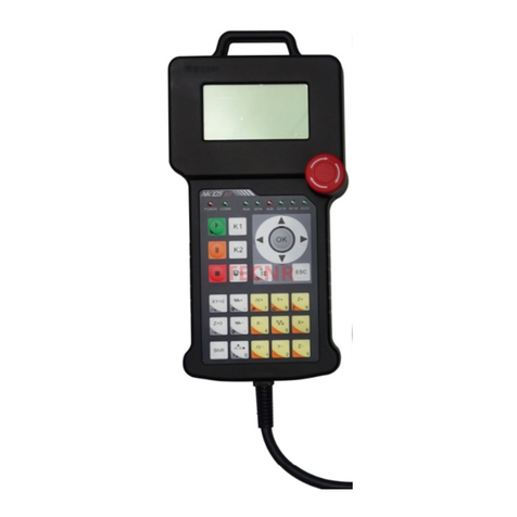
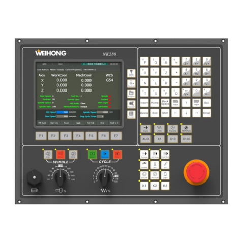
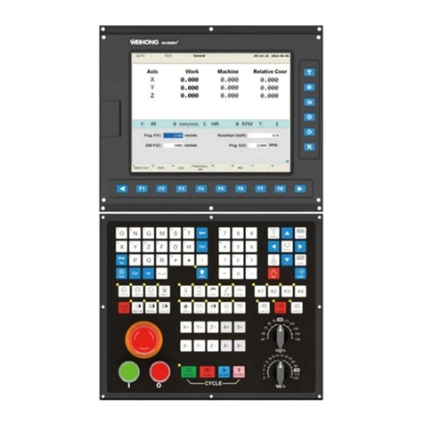
WEIHONG NK200 User manual

NK200 Integrated CNC System
Manufacturers’ Manual
14th Edition
Weihong Electronic Technology Co., Ltd.

The copyright of this manual belongs to Weihong Electronic Technology Co., Ltd. (hereinafter referred to as
Weihong Company). This manual and any image, table, data or other information contained in this manual may
not be reproduced, transferred, or translated without any prior written permission of Weihong Company.
The information contained in this manual is constantly being updated. You can login to the official website of
Weihong Company www.en.weihong.com.cn to download the latest PDF edition for free.

Specialized Concentrated Focused
Preface「I」
Preface
About This manual
This manual is intended for manufacturers. If you use Weihong CNC system for the first time, it is
suggested to read through this manual. If not, however, you can search for the desired information via
the contents.
With 7 chapters, this manual can be divided into 5 parts, as follows:
1) Preface, introducing the precautions about transportation and storage, installation, wiring,
debugging, usage and so on. You need to read them first carefully to ensure safe operations.
2) Hardware part, including chapter 1, 2 and 5. The first two introduce the product configuration,
hardware information and ports specification of NK200 while chapter 5 lists driver parameter
settings and wiring sketches of each brand.
3) Software part, including chapter 3. It illustrates detailed operations of single functionality and its
corresponding interfaces, which will be an intuitional guidance to users and operators in real
practice.
4) Maintenance part, including chapter 4. By reading the common troubleshooting, you can react to the
target and take corresponding steps in case of problems.
5) Appendix part: last part of this manual, consisting of chapter 6 and chapter 7, listing parameter
overview and the software license agreement respectively.
Applicable Product Model
This manual is applicable to NK200 integrated system. Refer to the table below for details.
Product Model
Remarks
NK200 Integrated
CNC system
Herein referred to NK200 as abbreviation, supporting three-axis standard
configuration and turn table configuration. In general, “the system”stands for
NK200 integrated CNC system without special notice.
Contact Us
You can contact us by the following info for technical support and pre-sales / after-sales service:
Company Name: Weihong Electronic Technology Co., Ltd.
Headquarters Address: No.1590, Huhang Rd., Fengxian, Shanghai, PRC 201400
Tel: +86-21-33587550
Fax: +86-21-33587519
Website: http://en.weihong.com.cn

Specialized Concentrated Focused
「II」Preface
Revision History
You can refer to the following table for the revision records of each edition.
Date
Edition
Revision
2016.02
R14
1) Contact information updated;
2) Wiring diagrams of Wise driver in section 5.3.1 updated;
3) Section 1.2.2 Mounting Dimensions added;
4) Section 2.1 updated;
5) Section 3.11.1 updated;
6) Fig. 3-44 Direction of Tool Compensation Updated;
7) Styles updated.
8) Other revisions.
2015.10
R12
The revisions are as below:
1) Update operation interface and instructions based on latest version;
2) Update the parameters information based on the latest version;
3) Update the operation system maintenance instructions;
4) Add new chapters, including extended coordinate system, tool
compensation and pulse equivalent setting;
5) Add WISE and MITSUBISHI MR-JE driver parameter settings and
wiring sketches;
6) Add system alarm specification part;
7) Other revisions.
Precautions
Precautions can be divided into caution and warning according to the degree of possible loss or injury in
case of negligence or omission of precautions stipulated in this manual.
CAUTION
: general info, mainly for informing, such as supplementary instructions and
conditions to enable a function. In case of negligence or omission of this kind of precautions, you may
not activate a function. Note that in some circumstances, negligence or omission of this kind of
precautions could cause physical injury or machine damage.
WARNING
: warning info requiring special attention. In case of negligence or omission of this
kind of precautions, you may suffer physical injury, or even death, machine damage or other losses.

Specialized Concentrated Focused
Preface「III」
WARNING
1) Precautions Related to Storage and Transportation
The products should be transported properly in terms of the weight;
An excess of specified quantity of stacking products is prohibited;
Climbing, standing or placing heavy loads on the products is prohibited;
Dragging or carrying the products via cables or devices connected to them is prohibited;
2) Precautions Related to Installation
Only when this equipment installed in the qualified electricity cabinet can it be used. The
construction of the cabinet must reach IP54 grade of protection;
Paste sealing strips on the joint of the cabinet to seal all the cracks;
Cable entry should be sealed while easy-to-open on the spot;
A fan or heat exchanger should be adopted for the heat dissipation and air convection of the
cabinet;
If a fan is adopted, air strainer is a must in air inlet or air outlet;
Dust or cutting fluids may have access to the CNC device via the tiny cracks and tuyere.
Therefore it is necessary to pay attention to the surroundings and air flow direction of the air
vent to make sure that the outflow gas is towards pollution source;
100 mm space should be preserved between the back of the CNC device and the cabinet wall
for plugging cable connected with the device and the ventilation & heat dissipation in the
cabinet;
Space between this device and other equipments should also be preserved according to the
requirements;
The product should be installed firmly and without vibration. During installing, casting,
knocking, striking, or loading on the product is forbidden;
To reduce electromagnetic interference, power-supply components used should be above AC
or DC 50V and the space between cable and CNC device should be preserved above 100mm;
It will be better if CNC device is installed at a position facilitating debugging and maintenance.
3) Precautions Related to Wiring
Only qualified people are allowed to participate in the wiring and checking;
The CNC device should be grounded reliably and grounding resistance should be less than 4

Specialized Concentrated Focused
「IV」Preface
WARNING
ohm. Neutral line is absolutely not allowed to replace earth wire. Otherwise, it may result in
malfunction of the device due to the interference;
Wiring should be firm and steady, or misoperation may occur;
Voltage values and positive & negative polarity of any connection plug should be in accordance
with specifications set forth in the manual, or it may result in breakdowns such as short circuit
and permanent damage to the device;
To guard against electric shock or CNC device damage, fingers should keep dry before
plugging or touching switch;
The connecting wire should not be damaged and squeezed, or the leakage or short circuit may
occur;
It is prohibited to plug or open the chassis of CNC device when power on.
4) Precautions Related to Running & Debugging
Parameters setting should be checked before running, since wrong setting may lead to
accidental movements;
Modification to parameters should be within the allowable range, or such breakdowns as
unsteady running and machine damage will occur.
5) Precautions in Use
Before power-on, please make sure that the switch is on blackout to avoid occasional start-up;
Please check the electromagnetic compatibility during electrical design in order to avoid or
reduce electromagnetic interference to the CNC device. A low pass filter should be employed
to reduce electromagnetic interference if there are other electrical devices nearby;
It is not allowed to frequently power on and power off. It is recommended to power up the
machine again at least one (1) minute later after power failure or blackout.

Specialized Concentrated Focused
Preface「V」
CAUTION
1) Precautions Related to Product and Manual
Matters related to restrictions and functions available stipulated in the manuals issued by the
machine manufacturer are prior to those in this manual;
This manual assumes all the optional functions are available, which you must confirm through
manuals issued by the machine manufacturer;
Please refer to manuals issued by the machine manufacturer for the instructions of machine
tools;
Functions, and software interfaces vary with the system and the version of software. Before
using the system, you must confirm the specifications.
2) Precautions When Opening the Package
Please make sure that the products are what you have ordered;
Check if the products are damaged in transit;
Check if the components and accessories are damaged or missing in terms of the detailed list;
Please contact us promptly if product discrepancy, accessory missing or transit damage
occurs.

Specialized Concentrated Focused
「VI」Contents
Contents
1Overview ......................................................................................................................1
1.1 System Configuration ............................................................................................................................. 2
1.2 An Introduction to Hardware.................................................................................................................. 2
1.2.1 Product Specification ................................................................................................................................. 2
1.2.2 Mounting Dimensions................................................................................................................................ 4
1.2.3 Connection Schematic Diagram................................................................................................................. 5
2Wiring...........................................................................................................................6
2.1 Signal Types............................................................................................................................................ 7
2.1.1 Binary input signal ..................................................................................................................................... 7
2.1.1.1 Input Binary......................................................................................................................................... 7
2.1.1.2 Output Binary...................................................................................................................................... 8
2.1.2 Relay output signal .................................................................................................................................... 9
2.1.3 Differential output signal........................................................................................................................... 9
2.1.4 Analog output signal.................................................................................................................................. 9
2.2 Terminal Introduction............................................................................................................................10
2.2.1 Input Interface of +24V Power ................................................................................................................ 10
2.2.2 Brake Interface ........................................................................................................................................ 10
2.2.3 Driver Interface........................................................................................................................................ 10
2.2.4 Handwheel Interface ............................................................................................................................... 11
2.2.5 Analog Interface ...................................................................................................................................... 12
2.2.6 USB Interface ........................................................................................................................................... 12
2.3 Port Specification of Terminal Board .....................................................................................................13
3Operation ................................................................................................................... 15
3.1 Debugging Steps ....................................................................................................................................18
3.2 Adjustment of Port Polarity ...................................................................................................................19
3.2.1 Ports Polarities......................................................................................................................................... 19
3.2.2 Manipulation Buttons.............................................................................................................................. 19
3.3 Adjustment of Axial Direction and Pulse Equivalent ..............................................................................21
3.3.1 Axial Direction Adjustment ...................................................................................................................... 21

Specialized Concentrated Focused
Contents「VII」
3.3.2 Pulse Equivalent Adjustment................................................................................................................... 22
3.3.3 Upper & Lower Limit Setting of Workbench Range................................................................................. 24
3.4 Returning to Machine Origin .................................................................................................................25
3.4.1 Process of Returning to Machine Origin .................................................................................................. 25
3.4.2 Principle of Returning to Machine Origin ................................................................................................ 26
3.4.3 Operation Interface of Backing to Machine Origin .................................................................................. 28
3.4.4 Parameters Specifications ....................................................................................................................... 30
3.4.5 FAQ & Troubleshooting ........................................................................................................................... 31
3.5 Spindle Parameters Adjustment ............................................................................................................33
3.5.1 Spindle Speed Setting .............................................................................................................................. 33
3.5.2 Parameter Specification .......................................................................................................................... 34
3.6 Adjustment of Velocity & Acceleration ..................................................................................................35
3.6.1 Feedrate Setting ...................................................................................................................................... 35
3.6.2 Traverse Speed Setting ............................................................................................................................ 35
3.6.3 Parameters Specification ......................................................................................................................... 36
3.7 Tool Presetting ......................................................................................................................................39
3.7.1 Software Interface ................................................................................................................................... 40
3.7.2 Floating Presetting................................................................................................................................... 40
3.7.3 Measure Tool Length/ Set Tool Length.................................................................................................... 41
3.7.4 First Presetting/ Second Presetting ......................................................................................................... 42
3.8 Offset Setting.........................................................................................................................................43
3.8.1 WCS (Workpiece Coordinate System) ..................................................................................................... 43
3.8.2 Extended Coordinate System .................................................................................................................. 45
3.8.3 Software Interface ................................................................................................................................... 46
3.9 Centering ...............................................................................................................................................47
3.9.1 Line Centering.......................................................................................................................................... 47
3.9.2 Circle Centering ....................................................................................................................................... 48
3.10 Simulation and Track .............................................................................................................................49
3.10.1 Simulation............................................................................................................................................ 49
3.10.2 Track .................................................................................................................................................... 50
3.11 Compensation .......................................................................................................................................50
3.11.1 Screw Error Compensation.................................................................................................................. 50
3.11.1.1 Causes of Screw Error and Compensation Method ........................................................................ 50

Specialized Concentrated Focused
「VIII」Contents
3.11.1.2 Screw Error Compensation Operation ............................................................................................ 52
3.11.1.3 Software Interface and Operation .................................................................................................. 54
3.11.2 Tool Compensation.............................................................................................................................. 55
3.11.2.1 Tool radius compensation(G40~G42) ............................................................................................. 57
3.11.2.2 Tool compensation types................................................................................................................ 57
3.11.2.3 Direction of tool compensation ...................................................................................................... 58
3.11.3 Across Quadrant Error (AQE) Compensation ...................................................................................... 59
3.12 Log.........................................................................................................................................................60
3.13 Program File Management ....................................................................................................................61
3.13.1 Program Wizard................................................................................................................................... 61
3.13.2 Array Processing .................................................................................................................................. 64
3.13.3 Program File ........................................................................................................................................ 65
3.14 Handwheel Operation ...........................................................................................................................69
3.14.1 Handwheel Mode ................................................................................................................................ 69
3.14.2 Handwheel Guide ................................................................................................................................ 71
3.15 System Management.............................................................................................................................72
3.15.1 System Info .......................................................................................................................................... 72
3.15.2 Register................................................................................................................................................ 72
3.15.3 Language.............................................................................................................................................. 74
3.15.4 System Update .................................................................................................................................... 74
3.15.5 Configuration Option........................................................................................................................... 74
3.16 Auxiliary Function..................................................................................................................................75
3.16.1 Jiggle .................................................................................................................................................... 75
3.16.2 Breakpoint Resume ............................................................................................................................. 76
3.16.3 Advanced Start .................................................................................................................................... 76
3.16.4 Parameter Backup ............................................................................................................................... 77
3.16.5 User Instruction ................................................................................................................................... 78
3.16.6 Coordinate Backup .............................................................................................................................. 78
3.17 Tool Magazine .......................................................................................................................................80
3.17.1 Automatic Tool Change of Linear Tool Magazine ................................................................................ 80
3.17.2 Automatic Tool Change of Circular Tool Magazine ............................................................................. 81
3.17.3 Tool Change Parameters ..................................................................................................................... 82
4Maintenance...............................................................................................................84

Specialized Concentrated Focused
Contents「IX」
4.1 Operating System Maintenance ............................................................................................................85
4.1.1 Software Upgrade.................................................................................................................................... 85
4.1.2 Mirror Upgrade........................................................................................................................................ 87
4.1.3 System Eboot ........................................................................................................................................... 87
4.1.4 Software Upgrade Interface .................................................................................................................... 88
4.2 Alarm Information .................................................................................................................................90
4.3 Common Troubleshooting .....................................................................................................................92
4.3.1 What should you do if the spindle does not rotate? ............................................................................... 92
4.3.2 What should you do if an axis does not move? ....................................................................................... 92
4.3.3 What should you do if servo motor of Z brake can’t be opened? ........................................................... 92
4.3.4 What should you do if machine tool returns to machine origin abnormally?......................................... 93
4.3.5 What should you do if the machine tool motions upward after arriving at the position of tool presetter
during presetting? ........................................................................................................................................................ 93
5Driver..........................................................................................................................94
5.1 Driver Parameters .................................................................................................................................96
5.1.1 Parameters Setting of WISE Servo Driver ................................................................................................ 96
5.1.2 Parameters Setting of YASKAWA Σ–ⅡServo Driver .............................................................................. 97
5.1.3 Parameter Setting of YASKAWA Σ-ⅤServo Driver................................................................................. 99
5.1.4 Parameter Setting of PANASONIC MINAS A4 Servo Driver ................................................................... 100
5.1.5 Parameter Setting of PANASONIC MINAS A5 Servo Driver ................................................................... 101
5.1.6 Parameter Setting of MITSUBISHI MR-JE Servo Driver .......................................................................... 102
5.1.7 Parameter Setting of MITSUBISHI MR-E Servo Driver ........................................................................... 103
5.1.8 Parameter Setting of DELTA ASDA-A Servo Driver ................................................................................ 104
5.1.9 Parameter Setting of DELTA ASDA-B Servo Driver................................................................................. 105
5.1.10 Parameter Setting of DELTA ASDA-A2 Servo Driver .......................................................................... 107
5.1.11 Parameter Setting of DELTA ASDA-B2 Servo Driver .......................................................................... 108
5.1.12 Parameter Setting of SANYO PY Servo Driver.................................................................................... 110
5.1.13 Parameter Setting of SANYO R Servo Driver ..................................................................................... 112
5.1.14 Parameter Setting of SANYO Q Servo Driver ..................................................................................... 113
5.1.15 Parameter Setting of KT270 Servo Driver.......................................................................................... 113
5.1.16 Parameter Setting of FUJI FALDIC-β Servo Driver.............................................................................. 115
5.1.17 Parameter Setting of STONE GS Servo Driver.................................................................................... 116
5.1.18 Parameter Setting of TECO TSDA Servo Driver.................................................................................. 117

Specialized Concentrated Focused
「X」Contents
5.2 Wiring Diagram of NK200 and Differential Input Stepping Driver ........................................................119
5.3 Wiring Diagram of NK200 and Servo Driver .........................................................................................119
5.3.1 Wiring Diagram of WISE Driver.............................................................................................................. 120
5.3.2 Wiring Diagram of YASKAWA AC Servo Driver....................................................................................... 121
5.3.3 Wiring Diagram of PANASONIC AC Servo Driver ................................................................................... 122
5.3.4 Wiring Diagram of MITSUBISHI MR-JE Servo Driver .............................................................................. 123
5.3.5 Wiring Diagram of MITSUBISHI MR-E Servo Driver ............................................................................... 124
5.3.6 Wiring Diagram of DELTA Servo Driver.................................................................................................. 124
5.3.7 Wiring Diagram of FUJI Servo Driver ..................................................................................................... 127
5.3.8 Wiring Diagram of HITACHI Servo Driver............................................................................................... 127
5.3.9 Wiring Diagram of SANYO PY Servo Driver ............................................................................................ 128
5.3.10 Wiring Diagram of SANYO R Servo Driver.......................................................................................... 128
5.3.11 Wiring Diagram of KT270 Servo Driver.............................................................................................. 129
5.3.12 Wiring Diagram of STONE GS Servo Driver........................................................................................ 129
5.3.13 Wiring Diagram of TECO TSDA Servo Driver ...................................................................................... 130
5.3.14 Wiring Diagram of TECO ESDA Servo Driver...................................................................................... 130
6Parameter Overview ................................................................................................. 131
7Software License Agreement ..................................................................................... 140

Specialized Concentrated Focused
Overview「1」
1 Overview
1.1 System Configuration ............................................................................................................................. 2
1.2 An Introduction to Hardware.................................................................................................................. 2
1.2.1 Product Specification ................................................................................................................................. 2
1.2.2 Mounting Dimensions................................................................................................................................ 4
1.2.3 Connection Schematic Diagram................................................................................................................. 5

Specialized Concentrated Focused
「2」Overview
1.1 System Configuration
NK200 integrated CNC system consists of the following components:
One NK200 host;
USB damper cable (80cm);
Servo cable, brand and length custom (one with brake line, while the other two without brake line);
Handwheel NK-MPG-06 (optional).
1.2 An Introduction to Hardware
1.2.1 Product Specification
A Picture of NK200 System
Fig. 1-1 A Picture of NK200 System

Specialized Concentrated Focused
Overview「3」
Front View of NK200
Display Area Function Selection Button
Area Letter Button
Area
Extended Button Area
Operation Button Area
Number & Direction
Button Area
Override Knobs
Fig. 1-2 Front View of NK200
Rear View of NK200
To X-axis driver
To Y-axis driver
To Z-axis driver
To handwheel
Input Ports
To related ports of machine tool
Output Ports
To related ports of machine tool
24V Power
Brake Interface
Analog Interface
USB Interface
Fig. 1-3 Rear View of NK200

Specialized Concentrated Focused
「4」Overview
1.2.2 Mounting Dimensions
After NK200 is installed on the machine tool, 100 mm space should be preserved in its surrounding for
convenience of wiring and ventilation in the cabinet.
The integral thickness of NK200 system is 108.7mm, including front panel and chassis. Hereinto, the
thickness of front panel is 5mm, and the thickness of rear chassis is 55.2mm. And the mechanical
dimension diagram of NK200 is as shown in Fig. 1-4 (Unit: mm). The cutout of NK200 is as shown in Fig.
1-5(Unit: mm).
机构尺寸图
370
196
356
230 9595
83.2
328
108.7
55.2
Fig. 1-4 Mounting Dimension of NK200
钣金开孔图
190
219
346
356
6-Φ5
Fig. 1-5 Cutout of NK200

Specialized Concentrated Focused
Overview「5」
1.2.3 Connection Schematic Diagram
Servo Motor
C
N
3
C
N
2
C
N
1
Servo Driver
Spindle MPG
Connection of Y/Z axis is
similar to that of X axis.
Input Ports
To related ports of
machine tool
Output Ports
To related ports of
machine tool
Inverter
Fig. 1-6 Connection Schematic Diagram of NK200

Specialized Concentrated Focused
「6」Wiring
2 Wiring
2.1 Signal Types............................................................................................................................................ 7
2.1.1 Binary input signal ..................................................................................................................................... 7
2.1.1.1 Input Binary......................................................................................................................................... 7
2.1.1.2 Output Binary...................................................................................................................................... 8
2.1.2 Relay output signal .................................................................................................................................... 9
2.1.3 Differential output signal........................................................................................................................... 9
2.1.4 Analog output signal.................................................................................................................................. 9
2.2 Terminal Introduction............................................................................................................................10
2.2.1 Input Interface of +24V Power ................................................................................................................ 10
2.2.2 Brake Interface ........................................................................................................................................ 10
2.2.3 Driver Interface........................................................................................................................................ 10
2.2.4 Handwheel Interface ............................................................................................................................... 11
2.2.5 Analog Interface ...................................................................................................................................... 12
2.2.6 USB Interface ........................................................................................................................................... 12
2.3 Port Specification of Terminal Board .....................................................................................................13

Specialized Concentrated Focused
Wiring「7」
2.1 Signal Types
The signal in NK200 integrated system can be classified into four types: binary input signal, relay output
signal, differential output signal and analog output signal.
2.1.1 Binary input signal
Binary input signal is active low and supports NO and NC input signals (through modifying input port
polarity in the software). Conducting to GND (i.e. grounding signal) in NO connection means signal
detected, and disconnecting with GND in NC connection means signal detected. (GND refers to
GROUND signal).
2.1.1.1 Input Binary
Connection between binary input and external circuit
The wiring method between binary input signal and a mechanical switch is shown in Fig. 2-1:
GND
IN
24V
I/O Board Card
Fig. 2-1 Connection of Mechanical Switch and Binary Input
Binary input signal can be connected with a photoelectric switch or a proximity switch of NPN (NO or NC)
type. Its joining method is as shown in Fig. 2-2.
24V
10K
COM
IN
24V
I/O Board Card External Input
Recommended
Fig. 2-2 Binary Input of NPN Type Connecting with Photoelectric Switch or Proximity Switch
Power requirement
It is recommended to adopt DC24V/4.5A switch power for relays on the terminal board. If there are a
great many DC 24V relays controlled by binary output signal, users can appropriately expand the power

Specialized Concentrated Focused
「8」Wiring
source capacity or add extra power (forcibly sharing ground with external power supply). Z-axis brake
and solenoid valve also need DC24V instead of external power to the greatest extent to reduce the
interference to CNC device by solenoid valve, etc.
2.1.1.2 Output Binary
Signal signature
The internal equivalent circuit of binary output is shown in Fig. 2-3.
+3.3V
OUTX
COM
+24V
Fig. 2-3 Equivalent Circuit of Binary Output Interface
Technical parameter
1) Supply voltage: 24VDC
2) Binary open-collector output
OC (open-collector) outputs drive capability with maximum allowable operating voltage 30VDC and
maximum allowable current 20mADC; so when the output terminal is active low, the maximum allowable
sucked current is 20mA.
Connection of binary output and external circuit
The connection of solid-state relay and binary output is shown in Fig. 2-4.
+
-
DC -
SSR
COM
+3.3V
OUTX
COM
+24V
Fig. 2-4 Connection of Solid-state Relay and Binary Output
Table of contents
Other WEIHONG Control System manuals

WEIHONG
WEIHONG Ncstudio V15 User manual

WEIHONG
WEIHONG NK280 User manual

WEIHONG
WEIHONG NK105 G2F User manual

WEIHONG
WEIHONG NK280B User manual

WEIHONG
WEIHONG 200 Series User manual

WEIHONG
WEIHONG NCStudio V12 User manual

WEIHONG
WEIHONG LS1500 User manual

WEIHONG
WEIHONG NcEditor V12 User manual

WEIHONG
WEIHONG NK300CX User manual

WEIHONG
WEIHONG NC65C User manual