SIP 01441 User manual

12
FOR HELP OR ADVICE ON THIS PRODUCT PLEASE CONTACT YOUR DISTRIBUTOR, OR
SIP DIRECTLY ON:
TEL: 01509500400
EMAIL: sales@sip-group.com or technical@sip-group.com
www.sip-group.com
Ref: 020714
Please dispose of packaging for the product in a responsible
manner. It is suitable for recycling. Help to protect the
environment, take the packaging to the local amenity tip and
place into the appropriate recycling bin.
1
Please read and fully understand the instructions in this manual
before operation. Keep this manual safe for future reference.
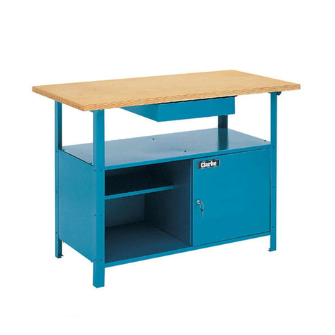
Oak Wooden Workbench
01441

2
11
NOTES

10
Secure the table-top to the leg-set
assembly with 4 x coarse thread bolts
with 4 x 8 mm (large) washers, taking
care not to over-tighten as this will
cause unwanted damage to the pi-
lot holes.
Turn the whole work-bench the correct way up and proceed to check and tight-
en all of the screws / bolts previously left loose.
Fitting the vice assemblies:
Note: Fit the vice assembly with the largest section of the gripping face
facing upwards (see below).
Line up the threaded bar and the 2 x support columns of the vice assembly with
the 3 holes on the front edge of the main table-top.
Push forwards and turn the handle clockwise to secure.
Proceed to follow these instructions to fit the 2nd vice assembly to the right
hand edge of the main table-top.
ASSEMBLY INSTRUCTIONS….cont
3
Note: If any parts are missing or damaged, contact your distributor for the
parts to be replaced.
A
B
C
D
E
CONTENTS AND ACCESSORIES
Ref. Description Qty. Ref. Description Qty.
A. Bench top. 1 N/A. M8 x 90 mm cap head bolts. 6
B. Main leg-set (left and right). 2 N/A. M8 recess nuts. 6
C. Main shelf. 1 N/A. 8 mm washers (small). 6
D. Upper brace (rear). 1 N/A. Coarse thread bolts. 4
E. Lower brace (front and rear). 2 N/A. 8 mm washers (large). 4
Note: The maximum weight the table can take is 300kg.

4
Drawer set:
A
B
C
D E
Extras:
A B
CONTENTS AND ACCESSORIES….cont
Ref. Description Qty. Ref. Description Qty.
A. Drawer front. 1 N/A. Wood screws. 8
B. Drawer back. 1 N/A. M6 x 37 mm cap head bolts. 4
C. Drawer sides. 2 N/A. M6 Recess nuts. 4
D. Drawer runner assemblies. 2 N/A. 6 mm Washers. 4
E. Drawer bottom. 1
Ref. Description Qty. Ref. Description Qty.
A. Vice assembly. 2 B. Work-piece support. 4
9
Follow the previous instructions to fit the opposite runner assembly, you may
need to lift the drawer slightly in order to ensure that the runner sits in the groove
on the drawer, and that the screws line up correctly with the pilot holes.
Fitting the main table-top to the leg-set assembly:
With the table-top still inverted, locate the 4 pilot holes where the leg-set assem-
bly is to be secured (see below).
Pilot hole
Pilot hole
Pilot hole
Pilot hole
Flip the leg-set assembly so that it is up-side down (like the main table-top) and
sit it onto the bottom of the table-top.
Line up the 4 holes (2 on each leg-set) on the leg-set assembly with the pilot
holes on the main table-top, ensure that the rear braces are set towards the
back i.e. the opposite side to the drawer assembly.
ASSEMBLY INSTRUCTIONS….cont

8
Fitting the drawer assembly to the table-top:
Set the table-top down so that the bottom of it faces upwards.
Fit 4 of the supplied wood screws into the 4 x holes on one of the drawer runner
assemblies.
Note: Fit the 4 x screws into the drawer runners so that the points protrude through
the bottom, this will make lining them up with the pilot holes where the runners
should be fitted on the bottom of the main table-top easier.
Runner
Pilot holes
Drawer stop
Line up the screws (front and back) with the pilot holes, making sure that the
“runner” faces inwards towards where the 2nd runner assembly is to be fitted
and that the drawer stop is towards the front.
Fully tighten the screws (take care not to over tighten the screws as this will dam-
age the hole and mean that the runner assembly is not as secure as it should
be) to secure the runner assembly in place.
Slide the drawer up against the runner assembly (above right), ensuring that the
groove on the drawer fits over the runner (above left).
ASSEMBLY INSTRUCTIONS….cont
5
Take one of the main legs-sets and locate the position for the upper brace (see
below).
Slide 1 x M8 x 90 mm cap head bolt with 1 x 8 mm washer (small) into the hole
on the outside of the leg-set.
Line up the upper brace with the cap head bolt and insert 1 x recess nut into
the hole on it.
Ensure the “channel” on the recess nut is in-line with the cap head bolt (see
above left).
Proceed to tighten the cap head bolt, making sure the upper brace fits into the
slot on the main-leg set, but do not fully tighten the bolt at this point.
Follow the instructions above to attach the upper brace to the opposite leg-set.
Repeat above steps for the rear lower brace (see below).
Rear upper and lower braces fitted.
ASSEMBLY INSTRUCTIONS

6
Slide the main shelf in between the
groove on the rear lower brace.
Put the front lower brace into the main shelf, making sure the main shelf slots
into the groove.
Note: You may need to open the leg-sets slightly to enable the lower brace (front)
to fit correctly. Always ensure that the main shelf is securely fitted into the groove on
rear and front lower brace before fully tightening all of the bolts etc.
Assembled
stand unit.
Rear lower brace groove
Push the front lower brace into the slots on either side of the main-legs.
Once in place, secure by using the same method as described for fitting the
upper brace.
ASSEMBLY INSTRUCTIONS….cont
7
Assembling the drawer set:
Take the front section of the drawer and lay it with the front facing down.
Select one of the drawer sides and sit it in-place against the front section.
If fitted correctly, the groove on the front section will match the groove on the
side section (see above).
Once in position, secure the 2 drawer sections together using the same method
as used to secure the leg sets to the upper and lower braces, but with the M6 x
37 mm cap head bolt with 6 mm washer and 6 mm recess nut.
Follow these instructions to fit and secure the opposite side section.
Slide the drawer bottom into the groove on the
drawer side sections until it is correctly located into
the groove on the front section (see right).
Fit the rear section of the drawers into the 2 x grooves (1 on each side) of the
side sections, ensuring that the bottom section fits into the groove on the rear
section.
Secure using the same method as previously used for the 2 x side sections.
Proceed to fully tighten all of the bolts associated with the drawer assembly.
ASSEMBLY INSTRUCTIONS….cont
Table of contents
Popular Tools Storage manuals by other brands

Griots Garage
Griots Garage 91582 User's manual and care instructions

Rittal
Rittal 4050.150 Assembly and operating instructions

kincrome
kincrome BLUE STEEL K7787 Operation manual

HOLZMANN MASCHINEN
HOLZMANN MASCHINEN WT39 user manual

MBA
MBA TORNADO Operator's manual

holzkraft
holzkraft HB 1401 Assembly instructions