Use of this manual
General description
and information
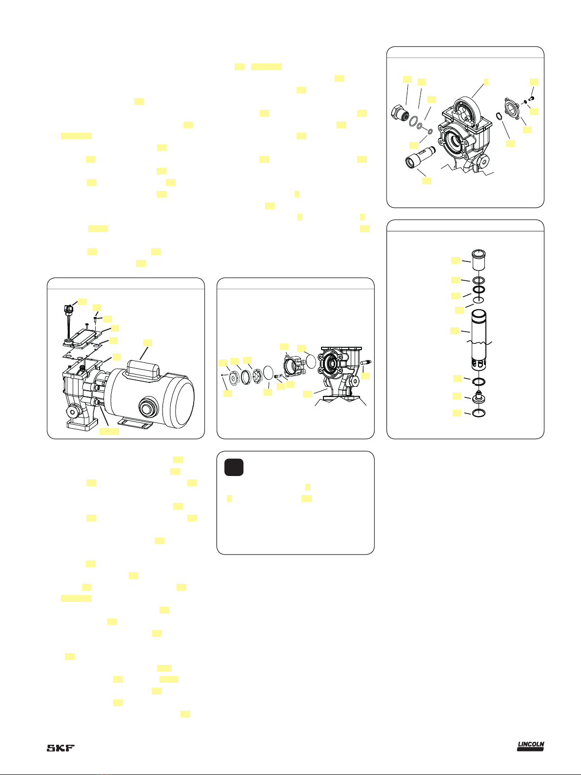
The Lincoln industrial rotary V AC electric
pump uses a V AC motor and a two stage
planetary gear drive. Grease output is pro-
portional to the pump revolutions per min-
ute. The pump is primarily designed for cen-
tralized lubrication systems such as the
single line parallel, single line progressive
and two line systems.
The pump is driven by the rotary motion
of the electric motor. Rotary motion is con-
verted to reciprocating motion through an
eccentric crank mechanism. The reciprocat-
ing action causes the pump cylinder to move
up and down. The unit is a positive displace-
ment double-acting pump as grease output
occurs during both the up and down stroke.
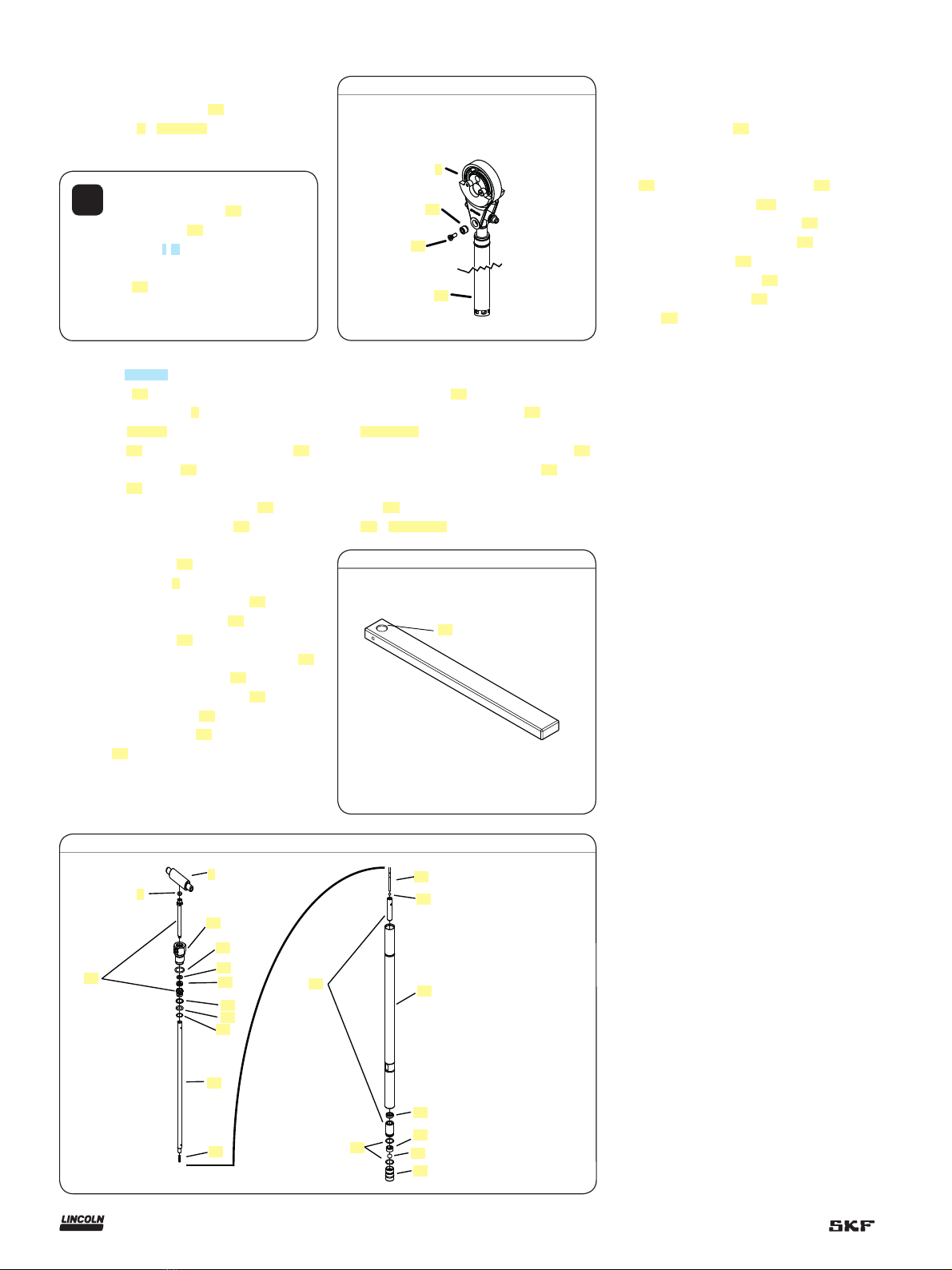
During the down stroke, the pump
cylinder is extended into the grease.
Through the combination of shovel action
and vacuum generated in the pump cylinder
chamber, the grease is forced into the pump
cylinder. Simultaneously, grease is
discharged through the outlet of the pump.
The volume of grease during intake is twice
the amount of grease output during one
cycle. During the upstroke, the inlet check
closes, and one half of the grease taken in
during the previous stroke is transferred
through the outlet check and discharged to
the outlet port. Typical output of the pump is
shown in table 2.
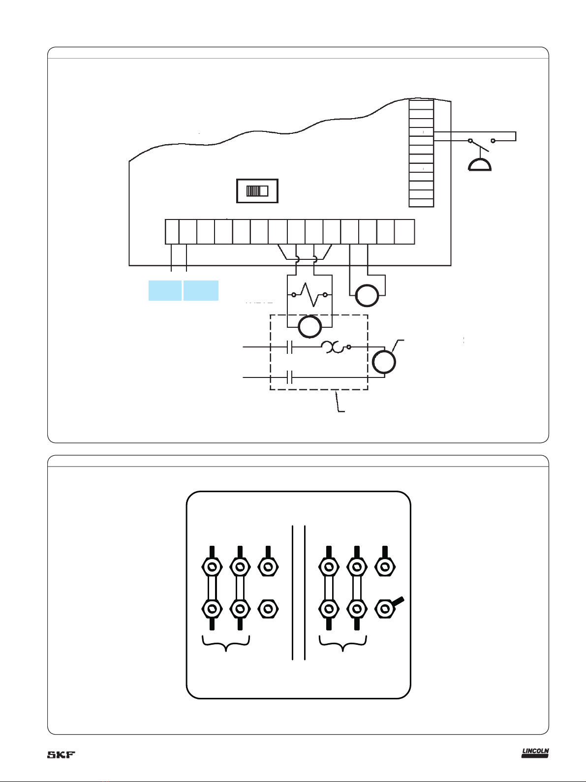
Fig. 1 is the electrical wiring schematic
for the pump with a controller and fig. 2 is
the electrical wiring schematic for the pump
motor.
Inspection
If over pressurizing of the equipment is
believed to have occurred, contact the
factory authorized warranty and service
center nearest you for inspection of the
pump.
Specialized equipment and knowledge is
required for repair of this pump.
Annual inspection by the factory author-
ized warranty and service center nearest
you is recommended.
Damaged Pumps
Do not use any pump that appears to be
damaged, badly worn or operates abnor-
mally. Remove the pump from service and
contact the factory authorized warranty and
service center nearest you for repairs.
A listing of authorized warranty and
service centers is available upon request.
Overview
This manual details the procedure that must
be followed while installing, operating, trou-
bleshooting and repairing the FlowMaster II
rotary driven V AC electric pump.
All required parts, tools, and equipment
needed to complete the operation of the
FlowMaster II rotary driven V AC electric
pump are defined and listed within this
manual.
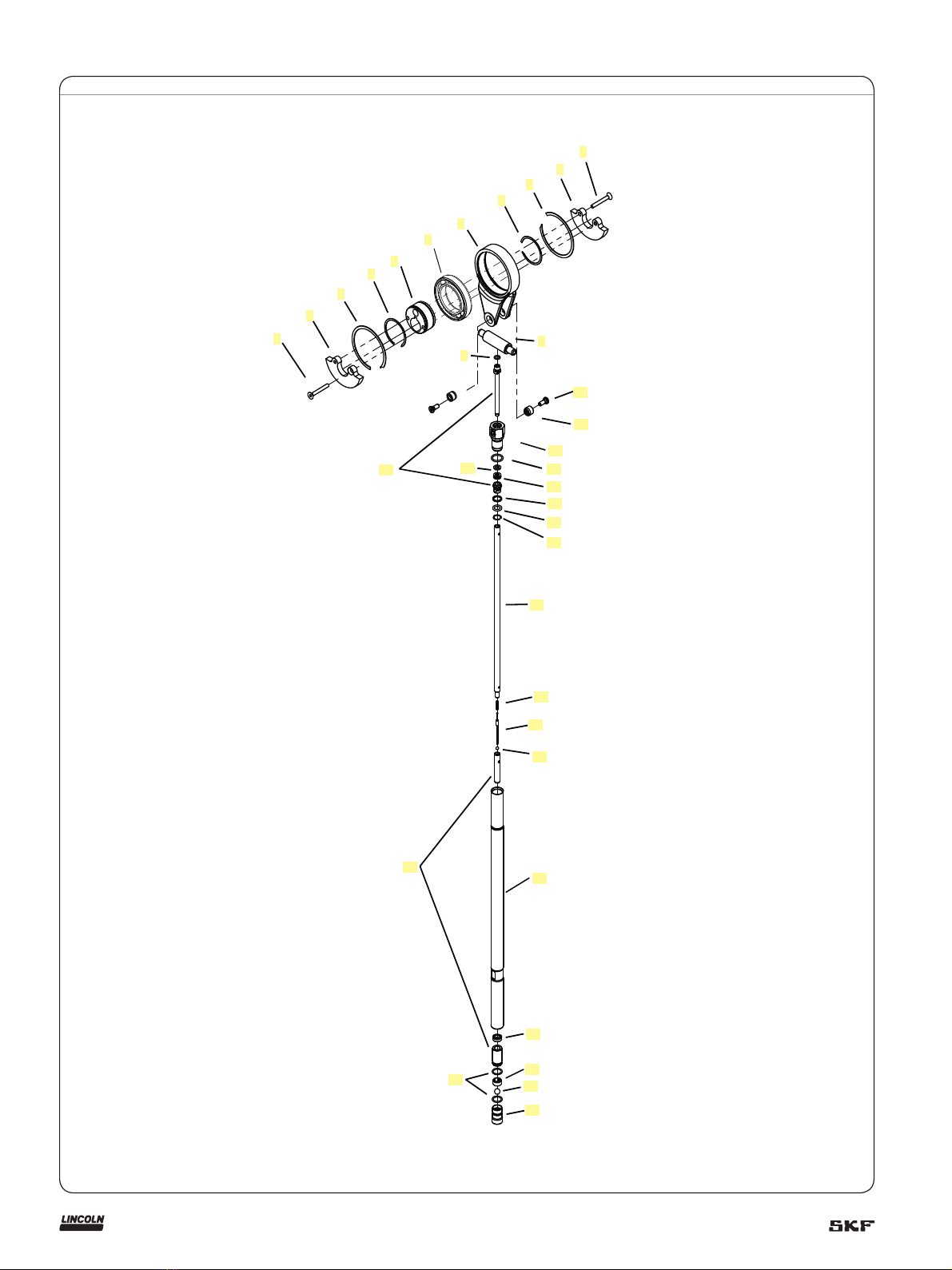
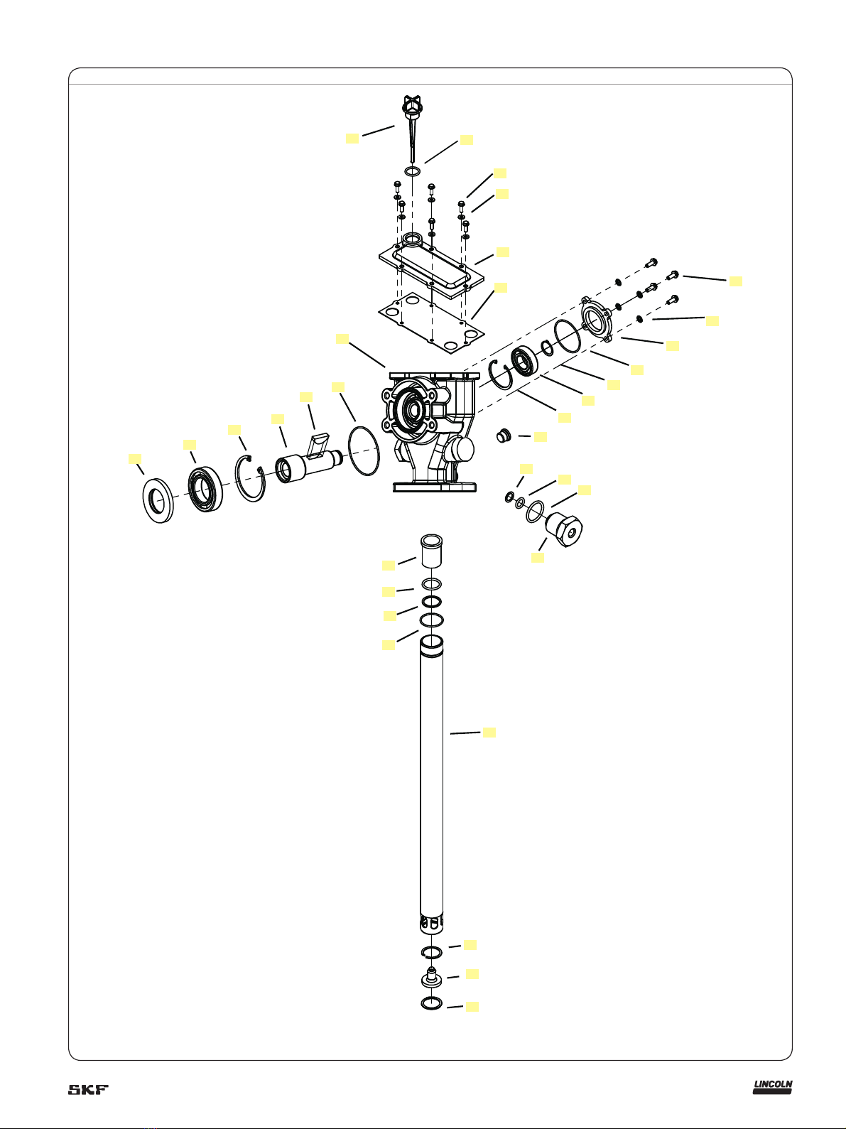
Review of the parts list and nomenclature
is recommended before starting
disassembly or operation.
Appropriate use
All pump models are exclusively designed to
pump and dispense lubricants using electric
power. The specifications are shown in
table 1 for the pump. The maximum specifi-
cation ratings should not be exceeded.
Any other use not in accordance with
instructions will result in loss of claims for
warranty and liability.
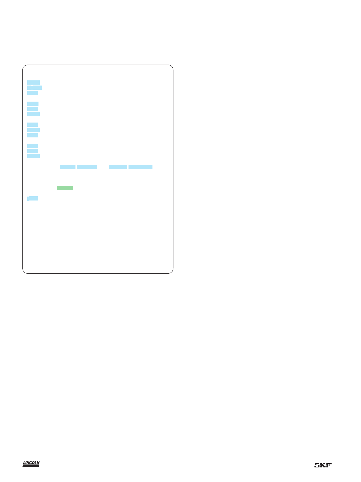
Table 2
Electric pump performance specifications
Temperature
°F (°C)
75 r/min. 92 r/min.
in3/min. (cm3)/min.)
80 (27) 5.4 (88) 6.7 (110)
40 (4) 5.2 (85) 6.4 (105)
20 (–7) 5.0 (82) 6.1 (100)
Table 1
Pump specifications
Operating temperature –40 to 150 °F (–40 to 65 °C)
Operating voltage 120/230 V AC, 50/60 Hz, 1 phase
Motor speed 1,425 r/min.@ 50 Hz, 1,725 r/min. @ 60 Hz
Pump speed 75 r/min. @ 50 Hz, 92 r/min. @ 60 Hz
Motor, power 1/2 HP (0,37 kW)
Current draw, † table 3
Output/pump cycle 0.07 in.3 (1,15 cm3)
Pump performance † table 2
Pump outlets 1/4 NPTF internal
Maximum outlet pressure 5,000 psi (345 bar) Test conducted with Alvania NLGI #2 grade grease at 1,000 psi (68 bar) back pressure
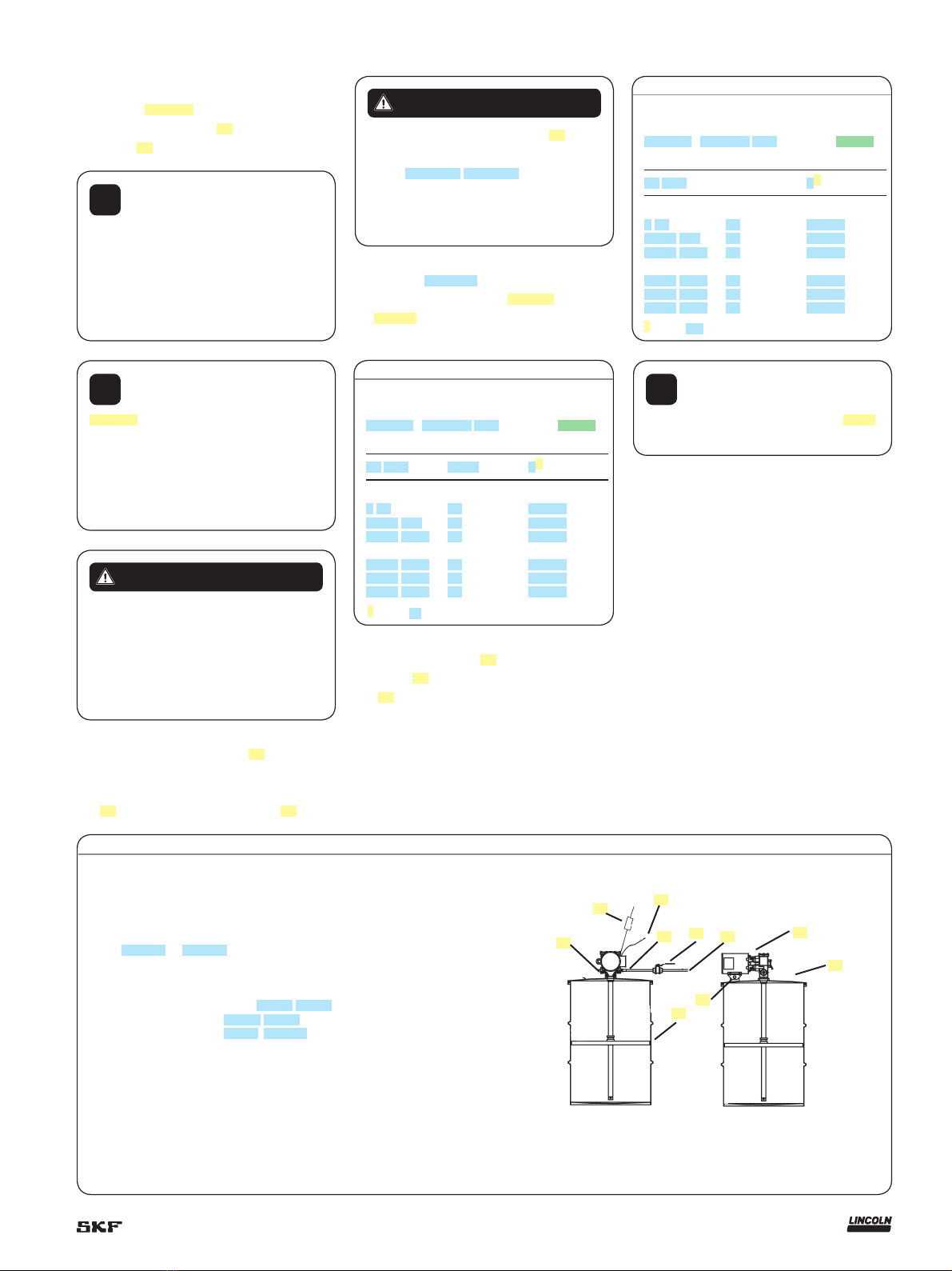
!Notice
Pumps are not recommended for
airless spray systems. They should be
converted from 19:1 to 34:1 gear ratio.
Please contact technical services for
component requirement.
4