Skil BW9501-00 User manual

WARNING: To reduce the risk of injury, the user must read and understand the
Owner’s Manual before using this product. Save these instructions for future reference.
AVERTISSEMENT : Afin de réduire les risques de blessure, l’utilisateur doit lire et
comprendre le guide d’utilisation avant d’utiliser cet article. Conservez le présent guide
afin de pouvoir le consulter ultérieurement.
ADVERTENCIA : Para reducir el riesgo de lesiones, el usuario debe leer y comprender
el Manual del operador antes de utilizar este producto. Guarde estas instrucciones para
consultarlas en caso sea necesario.
Owner’s Manual
Guide d’utilisation
Manual del propietario
For Customer Service
Pour le service à la clientèle
Servicio al cliente
Band Saw
Scie à ruban
Sierra de cinta
Model/ Modelo/ Modèle: BW9501-00
1-877-SKIL-999 OR www.skil.com

2
TABLE OF CONTENTS
General Safety Rules. ............................................3
Specic Safety Rules. ............................................4
Symbols.. . . . . . . . . . . . . . . . . . . . . . . . . . . . . . . . . . . . . . . . . . . . . . . . . . . . . . .7
Functional Descriptions and Specications. ........................11
Assembly and Installation. .......................................13
Adjustments. ..................................................16
Operation......................................................23
Maintenance. ..................................................27
Troubleshooting. ...............................................28
Limited Warranty of SKIL Consumer Bench Top Power Tools. .........29
WARNING
• Some dust created by power sanding, sawing, grinding, drilling and other construction
activities contains chemicals known to the State of California to cause cancer, birth defects
or other reproductive harm. Some examples of these chemicals are:
– Lead from lead-based paints.
– Crystalline silica from bricks, cement, and other masonry products.
– Arsenic and chromium from chemically-treated lumber.
• Your risk from these exposures varies, depending upon how often you do this type of work.
To reduce your exposure to these chemicals:
– Work in a well-ventilated area.
– Work with approved safety equipment, such as dust masks that are specially designed to
lter out microscopic particles.
• Avoid prolonged contact with dust from power sanding, sawing, grinding, drilling, and
other construction activities. Wear protective clothing and wash exposed areas with soap
and water. Allowing dust to get into your mouth or eyes or to lie on the skin may promote
absorption of harmful chemicals.

3
GENERAL SAFETY RULES
WARNING
Read all safety warnings, instructions, illustrations and specifications
provided with this power tool. Failure to follow all instructions listed
below may result in electric shock, re and/or serious injury.
SAVE ALL WARNINGS AND INSTRUCTIONS FOR FUTURE
REFERENCE.
Keep guards in place and in working order.
Remove adjusting keys and wrenches. Form a habit of checking to see that keys and
adjusting wrenches are removed from the tool before turning it on.
Keep the work area clean. Cluttered areas and benches invite accidents.
Don’t use in a dangerous environment. Don’t use power tools in damp or wet locations or
expose them to rain. Keep the work area well lit.
Keep children away. All visitors should be kept a safe distance from the work area.
Make workshop childproof with padlocks and master switches, or by removing starter
keys.
Don’t force tool. It will do the job better and safer at the rate for which it was designed.
Use the right tool. Don’t force tool or attachment to do a job for which it was not designed.
Wear proper apparel. Do not wear loose clothing, gloves, neckties, rings, bracelets, or other
jewelry which may get caught in moving parts. Nonslip footwear is recommended.
Wear protective hair covering to contain long hair.
Always use safety glasses. Also use a face or dust mask if the cutting operation is dusty.
Everyday eyeglasses only have impact resistant lenses. They are NOT safety glasses.
Secure work. Use clamps or a vise to hold work when practical. It’s safer than using your
hand and it frees both hands to operate the tool.
Don’t overreach. Keep proper footing and balance at all times.
Maintain tools with care. Keep tools sharp and clean for the best and safest performance.
Follow instructions for lubricating and changing accessories.
Disconnect tools before servicing or when changing accessories, such as blades, bits,
cutters, and the like.
Reduce the risk of unintentional starting. Make sure switch is in the off position before
plugging in.
Use recommended accessories. Consult the owner’s manual for recommended accessories.
The use of improper accessories may cause risk of injury to persons.
Never stand on the tool. Serious injury could occur if the tool is tipped or if the cutting tool is
unintentionally contacted.
Check damaged parts. Before further use of the tool, a guard or other part that is damaged
should be carefully checked to determine whether it will operate properly and perform its
intended function. Check for alignment of moving parts, binding of moving parts, brakeage of
parts, mountings, and any other condition that may affect tool’s operation. A guard or other
part that is damaged should be properly repaired or replaced.
Direction of feed. Feed work into a blade or cutter only against the direction of rotation of the
blade or cutter.
Never leave a tool running unattended. Turn power off. Don’t leave the tool until it comes to
a complete stop.
Do not abuse cord. Never carry tool by the cord or yank it to disconnect from receptacle.
Keep cord from heat, oil, and sharp edges.

4
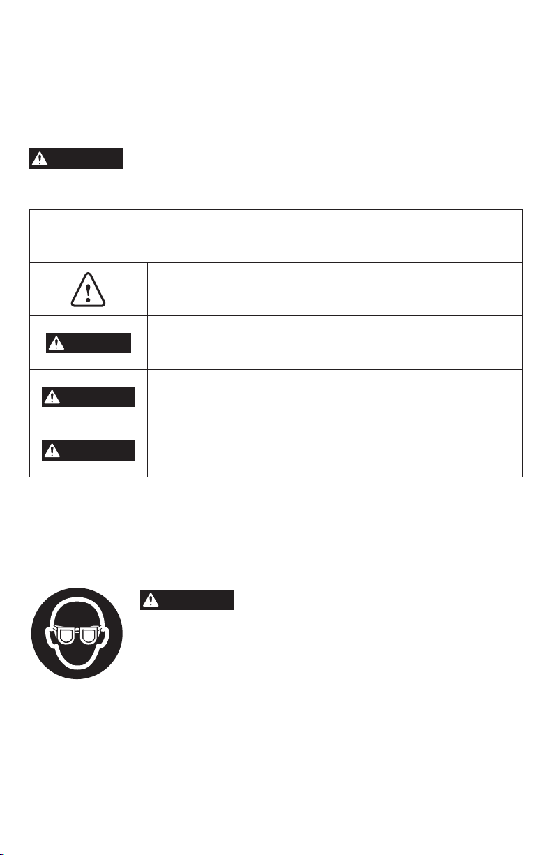
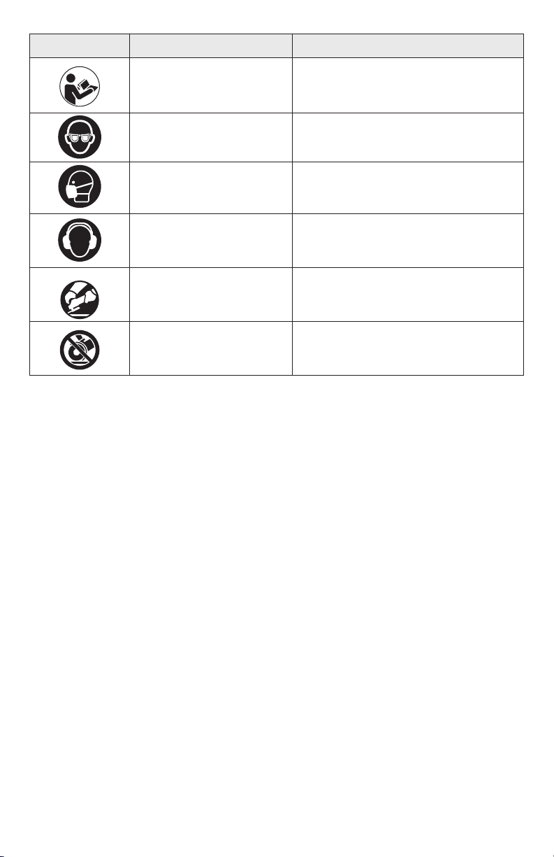
Protect your lungs. Wear a face or dust mask if the cutting operation is dusty.
Protect your hearing. Wear hearing protection during extended periods of operation.
Blade coasts after being turned off. Be mindful of the time it takes for the blade to come to
a complete stop.
Never use in an explosive atmosphere. Normal sparking of the motor could ignite fumes.
Inspect tool cords periodically. If damaged, have them repaired by a qualied service
technician at an authorized service facility.
Inspect extension cords periodically and replace if damaged.
Ground all tools. If tool is equipped with three-prong plug, it should be plugged into a
three-hole electrical receptacle. Check with a qualied electrician or service personnel if the
grounding instructions are not completely understood or if in doubt as to whether the tool is
properly grounded.
Use only correct electrical devices: 3-wire extension cords that have 3-prong grounding
plugs and 3-pole receptacles that accept the tool’s plug.
Do not modify the plug provided. If it will not t the outlet, have the proper outlet installed by
a qualied electrician.
Keep tool dry, clean, and free from oil and grease. Always use a clean cloth when cleaning.
Never use brake uids, gasoline, petroleum-based products, or any solvents to clean tool.
Stay alert and exercise control. Watch what you are doing and use common sense. Do not
operate tool when you are tired. Do not rush.
Do not use tool if switch does not turn on and off. Have defective switches replaced by an
authorized service center.
Before making a cut, be sure all adjustments are secure.
Be sure blade path is free of nails. Inspect and remove all nails from lumber before cutting.
Never touch blade or other moving parts during use.
Never start a tool when any rotating component is in contact with the workpiece.
Do not operate a tool while under the influence of drugs, alcohol, or any medication.
When servicing use only identical replacement parts. Use of any other parts may create a
hazard or cause product damage.
Use only recommended accessories listed in this manual. Use of accessories that are not
listed may cause the risk of personal injury.
Double check all setups. Make sure blade is tight and not making contact with saw or
workpiece before connecting to power supply.
SPECIFIC SAFETY RULES
To avoid injury from unexpected movement, make sure the saw is on a rm, level surface,
properly secured to prevent rocking. Make sure there is adequate space for operations. Bolt
the saw to a support surface to prevent slipping or sliding during operation.
Turn off and unplug the saw before moving it.
Use the correct size and style of blade.
Make sure the blade teeth point down and toward the table.
Blade guide, supports, bearings, and blade tension must be properly adjusted to avoid
accidental blade contact and to minimize blade breakage. To maximize blade support, always
adjust the upper blade guide and blade guard so that it barely clears the workpiece.
Use extra caution with very large, very small, or awkward workpieces.
Use extra supports to prevent workpieces from sliding off the table top.

5
Workpieces should be secured so they don’t twist, rock, or slip while being cut.
Plan intricate or small work carefully to avoid pinching the blade. Avoid awkward operations
and hand positions to prevent accidental contact with the blade.
Small pieces should be secured with clamps or xtures. Do not hold small pieces with your
hand because of the increased risk of touching the blade with your ngers.
Support round workpieces properly (use a V block or press it against the miter guide) to
prevent it from rolling and the blade from biting.
Cut only one workpiece at a time. Make sure the table is clear of everything except the
workpiece and its guides before you turn the saw on.
Always watch the saw run before each use. If there is excessive vibration, saw blade
stuttering, or unusual noise, stop immediately. Turn the saw off. Unplug it immediately. Do not
start the saw again until the problem has been located and corrected.
To free any jammed material, turn the switch off. Remove the safety key and unplug the saw.
Wait for all moving parts to stop before removing the jammed material.
Do not leave the work area until all moving parts have stopped. Unplug the saw from the
power source. Remove the safety key from the band saw and store it in a safe place, away
from children. Childproof the workshop!
Maintain proper adjustment of blade tension, blade alignment, blade guides and thrust
bearings.
Adjust blade guide assembly to 1/8” (3.2 mm) above workpiece before cutting.
Hold workpiece rmly against table.
Use recommended blade and speed for workpiece material.
Before starting, be certain the motor, table, attachments, and adjustment knobs are secured.
Do not operate with the upper and lower doors open.
Unplug saw before making blade changes, adjustments, or repairs.
Do not expose to rain or use in damp locations.
SAVE THESE INSTRUCTIONS. Refer to them frequently and use them to instruct other
users. If you loan someone this tool, loan them these instructions also.
IMPORTANT INFORMATION ABOUT EXTENSION CORDS
WARNING
An extension cord with adequate size conductors that is capable of
carrying the current for your tool must be used. This will prevent
excessive voltage drop, loss of power, or overheating. Grounded tools must use 3-wire
extension cords that have 3-prong plugs and receptacles.
NOTE: The smaller the gauge number, the heavier the cord.
RECOMMENDED SIZES OF EXTENSION CORDS FOR 120-VOLT
ALTERNATING CURRENT TOOLS
Tool's
Ampere
Rating
Cord Size in A.W.G. Wire Sizes in mm2
Cord Length in Feet Cord Length in Meters
25 50 100 150 15 30 60 120
3-6 18 16 16 14 0.75 0.75 1.5 2.5
6-8 18 16 14 12 0.75 1.0 2.5 4.0
8-10 18 16 14 12 0.75 1.0 2.5 4.0
10-12 16 16 14 12 1.0 2.5 4.0 —
12-16 14 12 — — — — — —

6
GROUNDING INSTRUCTIONS
In the event of a malfunction or breakdown,
grounding provides a path of least resistance
for electric current to reduce the risk of electric
shock. This tool is equipped with an electrical
cord that has an equipment-grounding
conductor and a grounding plug. The plug
must be plugged into a matching outlet that is
properly installed and grounded in accordance
with all local codes and ordinances.
Do not modify the plug provided. If it will not t
into the outlet, have the proper outlet installed
by a qualied electrician.
Improper connection of the equipment-
grounding conductor can result in a risk of
electric shock. The conductor with insulation
that has an outer surface that is green with
or without yellow stripes is the equipment-grounding conductor. If repair or replacement is
necessary, do not connect the equipment-grounding conductor to a live terminal.
Check with qualied electrician or service personnel if the grounding instructions are not
completely understood, or if in doubt as to whether the tool is properly grounded.
Use only 3-wire extension cords that have 3-prong grounding plugs and 3-pole receptacles
that accept the tool’s plug.
Repair or replace damaged or worn cord immediately.
This tool is intended for use on a circuit that has an outlet (sketch B). The tool has a grounding
pin (sketch A). A temporary adapter (sketches C and D) may be used to connect this plug
to a 2-pole receptacle (sketch C), if a properly grounded outlet is not installed by a qualied
electrician. The green-colored rigid ear, lug, and the like, extending from the adapter must be
connected to a permanent ground, such as a properly grounded outlet.
A.
B. C.
D.
Grounding
pin
Grounded means
Cover of
grounded
outlet box
Metal
screw

7
SYMBOLS
Safety Symbols
The purpose of safety symbols is to attract your attention to possible dangers. The safety
symbols and explanations with them deserve your careful attention and understanding. The
symbol warnings do not, by themselves, eliminate any danger. The instructions and warnings
they give are no substitutes for proper accident prevention measures.
WARNING
Be sure to read and understand all safety instructions in this Owner's
Manual, including all safety alert symbols such as “DANGER,”
“WARNING,” and “CAUTION” before using this tool. Failure to following all instructions listed
below may result in electric shock, re, and/or serious personal injury.
The denitions below describe the level of severity for each signal word. Please read the
manual and pay attention to these symbols.
This is the safety alert symbol. It is used to alert you to potential
personal injury hazards. Obey all safety messages that follow this
symbol to avoid possible injury or death.
DANGER
DANGER indicates a hazardous situation which, if not avoided, will
result in death or serious injury.
WARNING
WARNING indicates a hazardous situation which, if not avoided,
could result in death or serious injury.
CAUTION
CAUTION, used with the safety alert symbol, indicates a hazardous
situation which, if not avoided, will result in minor or moderate
injury.
Damage Prevention and Information Messages
These inform the user of important information and/or instructions that could lead to equipment
or other property damage if they are not followed. Each message is preceded by the word
“NOTICE”, as in the example below:
NOTICE: Equipment and/or property damage may result if these instructions are not followed.
WARNING
The operation of any power tools can result in foreign
objects being thrown into your eyes, which can result
in severe eye damage. Before beginning power tool operation, always
wear safety goggles or safety glasses with side shields and a full face
shield when needed. We recommend a Wide Vision Safety Mask for use
over eyeglasses or standard safety glasses with side shields. Always use
eye protection which is marked to comply with ANSI Z87.1.

8
SYMBOLS (CONTINUED)
IMPORTANT: Some of the following symbols may be used on your tool. Please study them
and learn their meaning. Proper interpretation of these symbols will allow you to operate the
tool better and safer.
Symbol Name Designation/Explanation
V Volts Voltage (potential)
AAmperes Current
Hz Hertz Frequency (cycles per second)
WWatt Power
kg Kilograms Weight
min Minutes Time
s Seconds Time
Wh Watt-hours Battery capacity
Ah Ampere-hours Battery capacity
ØDiameter Size of drill bits, grinding wheels, etc.
n0No-load speed Rotational speed, at no load
nRated speed Maximum attainable speed
…/min Revolutions or
reciprocations per minute Revolutions, strokes, surface speed,
orbits, etc. per minute
ft/min Feet per minute (fpm) Surface speed
0 Off position Zero speed, zero torque...
1,2,3,…
I,II,III, Selector settings Speed, torque or position settings. Higher
number means greater speed
Innitely variable selector
with off Speed is increasing from 0 setting
Arrow Action in the direction of arrow
Alternating current (AC) Type or a characteristic of current
Direct current (DC) Type or a characteristic of current
Alternating or direct current
(AC/DC) Type or a characteristic of current
Class II construction Designates Double Insulated Construction
tools.
Protective earth Grounding terminal
Li-ion RBRC seal Designates Li-ion battery recycling
program

9
Symbol Name Designation/Explanation
Read manual symbol Alerts user to read manual
Wear eye protection symbol Alerts user to wear eye protection
Wear a mask Recommendation for the operator to wear
dust mask.
Wear ear protection Recommendation for the operator to wear
hearing protection.
Always operate with two
hands Alerts user to always operate with two
hands
Do not use the guard for
cut-off operations
Alerts user not to use the guard for
cut-off operations

10
SYMBOLS (CERTIFICATION INFORMATION)
IMPORTANT: Some of the following symbols for certication information may be used on your
tool. Please study them and learn their meaning. Proper interpretation of these symbols will
allow you to operate the tool better and more safely.
Symbol Designation/Explanation
This symbol designates that this tool is listed by Underwriters
Laboratories.
This symbol designates that this component is recognized by
Underwriters Laboratories.
This symbol designates that this tool is listed by Underwriters
Laboratories, to United States and Canadian Standards.
This symbol designates that this tool is listed by the Canadian
Standards Association.
This symbol designates that this tool is listed by the Canadian
Standards Association, to United States and Canadian Standards.
This symbol designates that this tool is listed by the Intertek Testing
Services, to United States and Canadian Standards.

11
FUNCTIONAL DESCRIPTIONS AND SPECIFICATIONS
Fig. 1
o
5
10
PULL OUTTOLOCK
60
50
50
60
40
30
20
20
40
30
10
10
0
Blade Tension Lever
Tracking View Window
Upper Door Knob
Blade Guard
Saw Blade
Miter Guide
Lower Door Knob
Blade Tracking
Locking Nut
Dust Exhaust Port
Blade Guide
Assembly
Saw Base
Blade Guide
Adjustment Knob
Throat Plate
Angle Adjustment
Knob
Scale Indicator
Table Locking
Knob (2)
Blade Guide
Locking Knob
Blade Tracking Knob
Lower Door
Switch and
Safety Key
Upper Door
Saw Table

12
ANGLE ADJUSTMENT KNOB
Tilts the saw table for bevel cutting.
BLADE GUARD
Protects the operator from coming in contact
with the blade.
BLADE GUIDE ADJUSTMENT KNOB
Use the blade guide adjustment knob to
move the blade guide assembly up and
down in order to keep the blade from twisting
or breaking. Always lock the blade guide
assembly in place before turning on the band
saw.
BLADE GUIDES
Upper and lower blade guides help keep the
blade from twisting during operation.
DUST EXHAUST PORT
A 2-1/2 in. dust exhaust helps reduce your
exposure to dust when a dust bag or a shop
vacuum is attached.
MITER GUIDE
This guide aligns the wood for a crosscut or
miter cut. The easy-to-read indicator shows
the exact angle for a miter cut from 0° to the
right or left 60°.
BLADE TENSION LEVER
Controls blade tension when changing
blades and making adjustments for various
sawing applications.
SAW TABLE WITH THROAT PLATE
Your band saw has a saw table with tilt
control. The throat plate, installed in the saw
table at the factory, allows for necessary
blade clearance.
SCALE AND SCALE INDICATOR
The scale and scale indicator show the angle
the saw table is tilted for bevel cutting.
SWITCH AND SAFETY KEY
Your band saw has an easy access power
switch. To lock it in the OFF position, remove
the yellow safety key. Place the safety key in
a location inaccessible to children and others
not qualied to use the tool.
TABLE LOCKING KNOBS
Loosening the two table lock knobs allow
the saw table to be tilted for bevel cutting.
Tightening the table lock knobs lock the saw
table at desired angle.
BLADE TRACKING KNOB
Adjusts tracking to keep blade centered on
the upper wheel.
TRACKING VIEW WINDOW
The tracking view window makes tracking
adjustments easier to see.
SPECIFICATIONS
Rated Input 120 V ~, 60 Hz, 2.8 A
Blade Speed 1700/2500 FPM (Feet Per Minute)
Blade Width 1/8” (3.2 mm) – 3/8” (9.5 mm)
Blade Length 59-1/4” (150.5 cm) – 59-1/2” (151 cm)
Frame to Blade Capacity 9” (22.9 cm)
Table Size 12-1/4” x 12” (31.3 x 30.2 cm)
Table Tilting Angle 0°-45°
Table Miter Slot 3/8” (9.5 mm)
Cutting Capacity - Max Cutting Height 3-1/2” (8.89 cm)
Cutting Capacity - Max Cutting Width
(Throat Size) 9” (22.9 cm)
Dust Exhaust Port Ø2-1/2” (63.5 mm)

13
ASSEMBLY AND INSTALLATION
Loose Parts List (Fig. 2)
The following items are included with the band
saw:
No. Description Qty.
ASaw Table Assembly 1
BMiter Guide 1
C Hex Wrench, 2.5 mm 1
DCombination Tool 1
EHex Wrench, 6 mm 1
FFlat Wrench, 7x10 mm 1
GFlat Washer 2
HTable Locking Knob 2
Tools Needed (Not Included) (Fig. 3)
Combination square
Phillips screwdriver
Adjustable wrench
surface and examine it carefully.
● To avoid injury from unexpected starting
or electrical shock, do not plug the
power cord into a source of power during
unpacking and assembly. This cord must
remain unplugged whenever you are
adjusting/assembling the saw.
● The saw is heavy and should be lifted
with care. If needed, get the assistance of
someone to lift and move the saw.
WARNING
!
Fig. 3
Small Combination
Square Feeler Gauge
UNPACKING
WARNING
Do not use this product if any parts on the Loose Parts List are
already assembled to your product when you unpack it. Parts on this
list are not assembled to the product by the manufacturer and require customer installation.
Use of a product that may have been improperly assembled could result in serious personal
injury.
WARNING
If any parts are damaged or missing, do not operate this product
until the parts are replaced. Use of this product with damaged or missing
parts could result in serious personal injury.
WARNING
Do not attempt to modify this tool or create accessories not
recommended for use with this tool. Any such alteration or modication
is misuse and could result in a hazardous condition leading to possible serious personal injury.
WARNING
Do not connect to power supply until assembly is complete. Failure to
comply could result in accidental starting and possible serious personal injury.
– Carefully lift the saw from the carton and place on a level work surface.
– Inspect the tool carefully to make sure no breakage or damage occurred during shipping.
– Do not discard the packing material until you have carefully inspected and satisfactorily
operated the tool.
A
B
G
H E
F
C
D
Fig. 2

14
Installing The Saw Table Assembly (Fig. 4 & 5)
a. Remove the hex bolt, at washer, spring washer and wing nut from the saw table.
b. Align the slot on the saw table with the blade and slide the saw table around the blade from
the right side of the saw to the left as shown in Fig. 4.
c. While holding the saw table with your left hand, pull the angle adjustment knob away from
the saw frame (1), match the teeth on the saw table bracket with the teeth on the angle
adjustment knob. Release the knob (Fig. 5).
d. Fit the two pins on the frame into the slot in the saw table bracket (2).
e. Place one at washer onto the threaded end of the rst table lock knob, then repeat another.
Secure the saw table bracket to the saw frame by turning the two table lock knobs clockwise
(3).
f. Loosen the two table lock knobs, and turn the angle adjustment knob to ensure the saw
table can tilt smoothly. Then retighten the two lock knobs.
g. Tighten the screw on the scale indicator using the included combination tool.
h. Attach the hex bolt, at washer, spring washer and wing nut to the saw table as shown in
Fig. 4.
NOTE: The wing nut goes below the saw table.
Fig. 4
Hex Bolt
Saw Base
Saw Frame
Saw Table
Flat Washer
Spring Washer
Wing Nut
Fig. 5
2
13
3
Pin Table
Lock
Knobs
Flat Washer
Slot
Angle Adjustment Knob
Scale Indicator

15
Mounting Band Saw onto
Workbench (Fig. 6)
If the band saw is to be used in a permanent
location, the band saw must be mounted to a
rm supporting surface such as a workbench.
Four bolt holes in the saw’s base are intended
for this purpose.
a. Place band saw on the workbench. Using
the saw base as a pattern, locate and mark
the holes where the band saw is to be
mounted.
b. Drill holes through the workbench.
c. Place band saw on the workbench aligning
holes in the saw base with the holes drilled
in the workbench.
d. Insert bolts (not included) and tighten securely with lock washers and hex nuts (not
included). Bolts should be 1/4” (6 mm) (M6) in diameter and of sufcient length to
accommodate the saw base, lock washers, hex nuts, and the thickness of the workbench.
NOTE: All bolts should be inserted from the top. Install the lock washers and hex nuts from
the underside of the bench.
Carefully check the workbench after mounting to make sure that no movement can occur
during use. If any tipping, sliding, or walking is noted, secure the workbench to the oor before
operating.
Clamping Band Saw to
Workbench (Fig. 7)
If the band saw is to be used as a portable
tool, it is recommended that you fasten it
permanently to a mounting board that can
easily be clamped to a workbench or other
supporting surface. The mounting board
should be of sufcient size to avoid tipping of
saw while in use.
If you wish to be able to easily relocate
the band saw, fasten it permanently to a
mounting board that can easily be clamped
to a workbench or other stable surface. The
mounting board should be of sufcient size to
avoid tipping while the band saw is in use. Any
good grade plywood or chipboard with a 3/4”
(19 mm) thickness is recommended (Fig. 7).
a. Secure the band saw to the mounting board using 1/4” (6 mm) (M6) at head screws, lock
washers and hex nuts (not included). The screw length must be at least 2” (51 mm).
NOTE: For proper stability, holes must be countersunk so that the screw heads are ush with
the bottom surface of the mounting board.
b. Securely clamp the mounting board to a workbench using two or more work clamps (not
included).
60
60
50
50
40
40
30
30
20
20
10
10
0
Holes (4) in Saw Base
Fig. 6
60
60
50
50
40
40
30
30
20
20
10
10
0
Fig. 7 Nut
Washer
Saw
Base
Mounting
Board
Screw

16
ADJUSTMENTS
WARNING
To prevent personal injury, always disconnect the plug from the
power source when making adjustments.
WARNING
To avoid personal injury, maintain proper adjustment of blade ten-
sion, blade tracking, blade guides, and thrust bearings.
CAUTION
Saw blades are sharp. Always wear ANSI Z87.1-approved eye protec-
tion, as well as protective gloves, while handling saw blades.
Squaring The Saw Table to The
Blade (Fig. 8 & 9)
a. Turn the blade guide locking knob
counterclockwise to unlock the blade guide
assembly. Raise the blade guide assembly
as far as it will go by turning the blade guide
adjustment knob counterclockwise. Turn the
locking knob clockwise to the blade guide
assembly in place.
b. Place a small combination square (not
included) on the saw table beside the blade.
c. Loosen the two table locking knobs and
rotate the angle adjustment knob to tilt the
saw table up or down to align table 90°
to blade (0° position). Retighten the table
locking knobs.
d. Loosen the jam nut using the included at
wrench.
e. Turn the adjusting bolt until the bolt just
touches the saw housing.
f. Check squareness of the saw table to the
blade. Make readjustments if necessary.
g. Once squareness is conrmed, retighten the
jam nut.
h. Using the supplied combination tool, loosen
the scale indicator screw, set the scale
indicator to “0” (zero), then tighten the screw.
NOTE: Always make a test cut to ensure the
squareness of the blade prior to beginning any
operation. If not square, it may be necessary to
loosen the four bolts under the saw table to make the adjustment (miter slot must be parallel
to the saw blade). Once square, retighten bolts.
Blade Guide
Adjustment
Knob
Blade Guide
Assembly
Blade Guide
Locking
Knob
Fig. 8
0
5
10
15
20
25
Scale Indicator
Scale Indicator
Screw
Fig. 9
Table
Locking
Knobs
Small
combination
square
Adjusting
Bolt
Jam Nut
Saw Housing

17
Blade Tension Adjustment
(Fig. 10 & 11)
a. Disconnect the saw from power source.
b. Open the upper door by rotating the upper
door knob clockwise.
c. Raise up (1) and lift the tension lever (2) on
the top of the saw, then turn it clockwise (3)
to increase the tension on the blade.
d. Turn the tension lever counter-clockwise (4)
to reduce the tension on the blade.
e. Press down the blade tension lever on the
top of the saw to engage tension.
f. With a gloved nger, pluck the back straight
edge of the saw blade like a guitar string.
Sound becomes higher pitched as tension
increases. Never increase blade tension so
tight as to completely compress the spring.
When completely compressed, the spring can
no longer act as a shock absorber.
Too much tension may cause the blade to
break. Thicker workpieces require higher
tension; maximum tension is not needed for all
cuts. Too little tension may cause the blade to
slip on the wheels.
Blade Tracking Adjustment (Fig. 12)
NOTE: The band saw blade tracking is pre-set at the factory. Check for proper blade tension
before making any blade tracking adjustments.
Disconnect the saw from power source and open the upper door by rotating the upper door
knob clockwise. Rotate the upper wheel clockwise and check the position of the blade on the
wheel. The blade should remain in the center of the wheel.
If an adjustment is needed:
a. Loosen the tracking locknut.
If the blade moves toward the front edge of the wheel:
b. Turn the blade tracking knob slightly clockwise. At the same time, keep turning the upper
wheel until the blade is centered.
If the blade moves toward the back edge of the wheel:
c. Turn the blade tracking knob slightly counterclockwise. At the same time, keep turning the
upper wheel until the blade is centered.
d. Tighten the blade tracking locknut when you are nished making adjustments.
e. Close and lock the upper door by rotating the upper door knob counterclockwise.
f. Turn on the saw.
Fig. 11
1
2
43
To Decrease
Tension
To Increase
Tension
Fig. 10

18
g. Verify saw blade is centered on the wheel (through the tracking view window). If not
centered, repeat above steps.
Fig. 12
Tracking
View
Window
Tracking
Locknut
Upper
Wheel
Tracking
View
Window
Tracking
Knob
Upper
Door
Knob
Blade Guide Assembly
Adjustment (Fig. 13)
To prevent the blade from twisting or breaking,
the blade guide assembly should always be
set approximately 1/8” (3.2 mm) above the
workpiece.
a. Disconnect the saw from power source.
b. Turn the blade guide locking knob
counterclockwise to unlock the blade guide
assembly.
c. Use a scrap piece of the same wood you
are about to cut as a guide, to set the height
of the blade guide assembly. Raise or lower
the blade guide assembly by turning the
blade guide adjustment knob.
d. Lock the blade guides in place by turning the locking knob clockwise.
WARNING
Always lock the blade guide assembly in place before turning on the band
saw.
Blade Guide
Adjustment
Knob
Blade Guide
Assembly
Blade Guide
Locking
Knob
Fig. 13

19
Thrust Bearings and Blade Guide
Adjustments (Fig. 14 & 15)
To Adjust Thrust Bearings:
a. Disconnect the saw from power source.
b. Open the upper door.
c. Open the blade guard by pulling the left side
of the guard out and away from the wheel.
d. Loosen the thrust bearing screw with the
included combination tool and move the
thrust bearing forward or backward, using a
feeler gauge (not included) and make sure
the bearing is 1/32” (0.8 mm) behind the
blade. Tighten the screw.
To Adjust Blade Guide:
e. Loosen the right blade guide screw with the included 2.5 mm hex wrench and adjust the
right blade guide set screw with the included combination tool and move the right blade
guide to contact the blade band. Tighten the blade guide screw.
f. Loosen the left blade guide screw, adjust the left blade guide screw with the included
combination tool and move the left blade guide as close to the blade band as possible
without pinching it. Using a feeler gauge (not included), make sure the clearance between
the guide and the blade band measures 0.004 – 0.01” (0.1 – 0.25 mm). Tighten the blade
guide screw.
g. Repeat above steps for the lower blade thrust bearing and blade guides.
h. Close the blade guard and upper/lower doors.
NOTE: Thrust bearings and blade guides do not touch the saw blade teeth during adjustment.
Fig. 15
>PA6+%15GF<
1/32" (0.8 mm) Thrust Bearing
Thrust Bearing
Screw
Blade Guide Set
Screws
Blade Guide
0.004 - 0.01" (0.1 - 0.25 mm)
Blade Guide Screw
Fig. 14

20
Blade Installation and Adjustment (Fig. 16)
WARNING
Blade teeth are sharp. Use care when handling a band saw blade.
a. Disconnect the saw from power source.
b. Loosen and remove the hex bolt, at washer, spring washer and wing nut from the saw
table.
c. Open the upper and lower doors.
d. Open the blade guard by pulling the left side of the guard out and away from the wheel.
e. Raise the blade tension lever to reduce tension on the blade.
f. Remove the old blade. Slide the blade out and away from the upper and lower blade guides.
g. Place the new blade in position around the upper and lower wheels and between the upper
and lower blade guides.
NOTE: The teeth of the blade should be facing downward and facing the front of the tool.
h. Center the blade on the upper and lower wheels. Turn the upper wheel slowly to check the
position of the blade.
i. Turn the blade tension lever clockwise to increase the tension on the blade.
j. Make sure the blade is still centered on the upper and lower wheels and that it moves freely
through the blade guides.
k. The blade must be adjusted properly before operating the saw:
– See section “BLADE TENSION ADJUSTMENT”.
– See section “BLADE TRACKING ADJUSTMENT”.
– See section “BLADE GUIDE ASSEMBLY ADJUSTMENT”.
l. Close blade guard and upper/ lower doors.
m. Reattach the hex bolt, at washer, spring washer and wing nut to the saw table
Tighten the wing nut securely.
Fig. 16
Hex Bolt
Upper Wheel
Lower Wheel
Blade Guard
Upper Blade Guides
Saw Blade
Lower Blade Guides
Flat Washer
Spring Washer
Wing Nut
Table of contents
Languages:
Other Skil Saw manuals
Popular Saw manuals by other brands

HIKOKI
HIKOKI C 12LCH Handling instructions

Parkside
Parkside PDKS 120 A1 operation and safety notes original operating instructions

Miller Electric
Miller Electric MCS-13H Specification sheet

Hafco
Hafco EB-280DSV Operation manual

Skymsen
Skymsen SI-282HD instruction manual

Makita
Makita HS0600 instruction manual