Page 5 of 69
SKIPPER Electronics AS
Version: 20100811 Sw 1.12.3.0
GDS102 Operation and Installation Manual
1. Introduction
System Summary
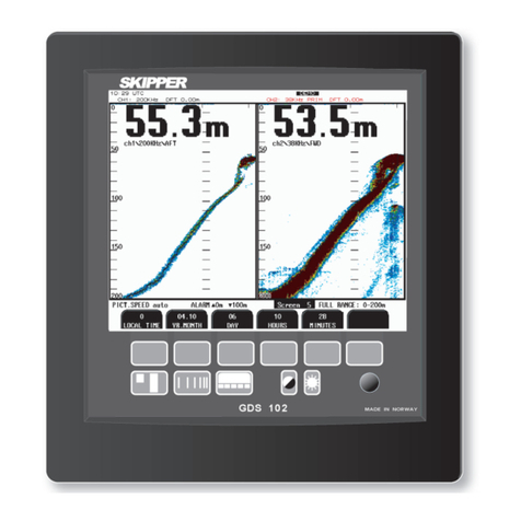
GDS102 is a dual channel navigation sounder with a large colour LCD. The echo sounder graphics is
continuously shown on the LCD along with complete navigational details. It is possible to connect an
external printer to the operator unit. The sounder contains a Compact Flash which keeps 24 hours of
recorded information. Depth, time and all available navigation data are stored continuously so that the last
24 hours of information is always available. All this information may also be printed on the external printer.
All IMO (International Maritime Organization) requirements are met or exceeded. Comprehensive interfaces
are available including NMEA 0183 inputs and outputs.
Transducers
GDS102 is prepared for connection of 1 or 2 transducers with a resonant frequency in the range of 10 - 265
kHz. Transmitter stage of the transceiver PCB is tuned to impedance of 100 Ohm, so the transducer type (if
not supplied by SKIPPER) should be selected accordingly. Channel 1 is optimized for higher frequencies
(50 - 265 kHz), while channel 2 is for a lower frequency range (10 - 50 kHz). The operating frequencies for
both channels are preset in production to 50 kHz (ch 1) and 200 kHz (ch 2) or to customer specication. The
frequencies can be changed with DIP switches on the transceiver PCB, if necessary. Ref. “Frequency setup”,
chapter 4 for further instructions.
Primary/Secondary Channels Concept
In order to avoid confusion if two transducers are used simultaneously, one of the channels is assigned as
primary, the other one - secondary. Assignment of these is programmable by the user, ref. g 2.5, screen 4.
Data from the primary channel will always be used to set analogue outputs and in the NMEA standard
sentences. Note: If SKIPPER proprietary message is enabled, the depth information from both channels will
be provided and can be recognized by NMEA listeners. Ref. “NMEA Setup” chapter 4 for further details
about SKIPPER PSKPDPT format.
It is advisable, that the channel which has a transducer with better installation and performance conditions
is assigned as primary. In most cases that would be the channel with a transducer installed forward. It is
also important that the primary channel is set to an IMO approved transducer for the whole system to be
approved.
Operator Panel and Data Entry
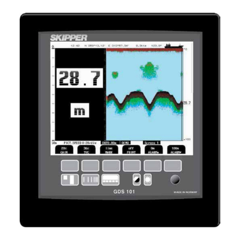
The operator unit contains a colour LCD, a keyboard with xed keys, soft keys and a rotating encoder. The
function of each soft key depends on the active screen. The buttons are labeled on the lower rim of the LCD.
Several screens are used to enter various settings and calibration parameters. Each screen has a selection
of soft key buttons. Screens 1 through 3 are primary operation screens with appropriate operator controls.
Screens 4 through 12 are calibration, setup and system supervision screens. The various screens will be
described in detail later.
The LCD is backlit, and backlight intensity may be adjusted by the user. Day or night vision modes can be
selected according to the ambient light conditions. The echogram is normally displayed continuously on the
LCD. An optional external printer can be connected, if hardcopy documentation is required. The operator
unit is normally ush mounted.


