manuals.online logo
Brands
  1. Home
  2. •
  3. Brands
  4. •
  5. Sky Angel
  6. •
  7. Toy
  8. •
  9. Sky Angel Jas-39 User instructions

Sky Angel Jas-39 User instructions

Other Sky Angel Toy manuals

Sky Angel G202-3D User instructions

Sky Angel

Sky Angel G202-3D User instructions

Sky Angel Mini Warbirds Sea fury User instructions

Sky Angel

Sky Angel Mini Warbirds Sea fury User instructions

Sky Angel Nano MIG-29 User instructions

Sky Angel

Sky Angel Nano MIG-29 User instructions

Sky Angel F/A-18 User instructions

Sky Angel

Sky Angel F/A-18 User instructions

Sky Angel 35MM Nano Series User instructions

Sky Angel

Sky Angel 35MM Nano Series User instructions

Sky Angel F-35 User instructions

Sky Angel

Sky Angel F-35 User instructions

Sky Angel AMX User instructions

Sky Angel

Sky Angel AMX User instructions

Sky Angel Mirage 2000 User instructions

Sky Angel

Sky Angel Mirage 2000 User instructions

Sky Angel A-6 User instructions

Sky Angel

Sky Angel A-6 User instructions

Sky Angel HR-100 User instructions

Sky Angel

Sky Angel HR-100 User instructions

Sky Angel 3D SU-26 User instructions

Sky Angel

Sky Angel 3D SU-26 User instructions

Sky Angel L-39 User instructions

Sky Angel

Sky Angel L-39 User instructions

Sky Angel T-33 User instructions

Sky Angel

Sky Angel T-33 User instructions

Sky Angel Nano F15 User instructions

Sky Angel

Sky Angel Nano F15 User instructions

Sky Angel DHC User instructions

Sky Angel

Sky Angel DHC User instructions

Sky Angel Mini Warbirds A-1 User instructions

Sky Angel

Sky Angel Mini Warbirds A-1 User instructions

Sky Angel AMX User instructions

Sky Angel

Sky Angel AMX User instructions

Sky Angel 3D cap-232 User instructions

Sky Angel

Sky Angel 3D cap-232 User instructions

Popular Toy manuals by other brands

FUTABA GY470 instruction manual

FUTABA

FUTABA GY470 instruction manual

LEGO 41116 manual

LEGO

LEGO 41116 manual

Fisher-Price ColorMe Flowerz Bouquet Maker P9692 instruction sheet

Fisher-Price

Fisher-Price ColorMe Flowerz Bouquet Maker P9692 instruction sheet

Little Tikes LITTLE HANDIWORKER 0920 Assembly instructions

Little Tikes

Little Tikes LITTLE HANDIWORKER 0920 Assembly instructions

Eduard EF-2000 Two-seater exterior Assembly instructions

Eduard

Eduard EF-2000 Two-seater exterior Assembly instructions

USA Trains EXTENDED VISION CABOOSE instructions

USA Trains

USA Trains EXTENDED VISION CABOOSE instructions

Modellbau Laffont Z1601 Assembly instructions

Modellbau Laffont

Modellbau Laffont Z1601 Assembly instructions

NOCH 12905 instruction manual

NOCH

NOCH 12905 instruction manual

Eduard Ki-61-Id quick start guide

Eduard

Eduard Ki-61-Id quick start guide

Viessmann Vollmer 45616 Mounting instruction

Viessmann

Viessmann Vollmer 45616 Mounting instruction

Vollmer 42004 Mounting instruction

Vollmer

Vollmer 42004 Mounting instruction

Phoenix Model CLASSIC-EP instruction manual

Phoenix Model

Phoenix Model CLASSIC-EP instruction manual

H-KING Sopwith Camel British WW1 Fighter instruction manual

H-KING

H-KING Sopwith Camel British WW1 Fighter instruction manual

MODSTER Predator 4x4 Crawler user manual

MODSTER

MODSTER Predator 4x4 Crawler user manual

DHK Hobby 8136 User instruction manual

DHK Hobby

DHK Hobby 8136 User instruction manual

THUNDER TIGER Raptor 50 V2 kit manual

THUNDER TIGER

THUNDER TIGER Raptor 50 V2 kit manual

Timberkits Skateboarder instructions

Timberkits

Timberkits Skateboarder instructions

Hangar 9 Funtana 125 Assembly manual

Hangar 9

Hangar 9 Funtana 125 Assembly manual

manuals.online logo
manuals.online logoBrands
  • About & Mission
  • Contact us
  • Privacy Policy
  • Terms and Conditions

Copyright 2025 Manuals.Online. All Rights Reserved.

Assembly
Assembly
Assembly
Assembly and
and
and
and Operating
Operating
Operating
Operating Manual
Manual
Manual
Manual
J as-39
SPECIFICATION:
SPECIFICATION:
SPECIFICATION:
SPECIFICATION:
�
�
�
�Length:
Length:
Length:
Length: 20-1/2"
20-1/2"
20-1/2"
20-1/2" (700
(700
(700
(700 mm)
mm)
mm)
mm)
�
�
�
�Wing
Wing
Wing
Wing Span:
Span:
Span:
Span: 20
20
20
20 -
-
-
- 1
1
1
1 /10"(
/10"(
/10"(
/10"( 510
510
510
510 mm)
mm)
mm)
mm)
�
�
�
�Flying
Flying
Flying
Flying Weight:
Weight:
Weight:
Weight: 11
11
11
11 -
-
-
- 1
1
1
1 /
/
/
/ 2
2
2
2 oz.
oz.
oz.
oz. (
(
(
( 325
325
325
325 g)
g)
g)
g)
Assembly
Assembly
Assembly
Assembly and
and
and
and Operating
Operating
Operating
Operating Manual
Manual
Manual
Manual
2
2
2
2
Dear
Dear
Dear
Dear customer,
customer,
customer,
customer,
Congratulations on your choice of a
factory-assembled model aircraft from the
SKYANGEL
SKYANGEL
SKYANGEL
SKYANGEL range
range
range
range and thank you for placing your
trust in us.
Very little preparation work is required to get this
model ready to
fly.
To
operate your new model
safely it is important that you read through all of
the instructions and safety information included
with your model, before you fly it for the first time.
The illustrations in this manual show the Silver
version of the model with factory applied decals.
The
The
The
The power
power
power
power system
system
system
system
The model is powered by a brushless outrunner
motor and ducted fan, both of which are
factory-installed on the Ready-To-Fly version.
The motor is connected to the electronic speed
controller which is factory calibrated on the
Ready-To-Fly version. All that is required is to
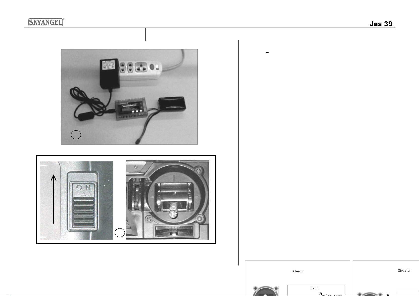
charge the Li-Po battery, following the safety
instructions, and connect the battery to the
electronic speed controller .
The
The
The
The radio
radio
radio
radio control
control
control
control system
system
system
system
To
fly the Jas 39 you will need a radio control
system with at least four channels. 2.4GHz radios
systems are recommend ed , similar to the unit
included with our deluxe version.
The power for the receiver is drawn from the
electronic speed controller ’ s integral BEC system.
The electronic speed controller is located inside of
the fuselage, in front of the ducted fan.
When you wish to fly the model, always make sure
the transmitter is in the “ OFF ” position. Move the
throttle stick to the “ OFF ” position as well. Then
connect the flight battery to the electronic speed
controller .
Switch off in the reverse order: disconnect the
battery from the electronic speed controller first,
and then switch off the transmitter.
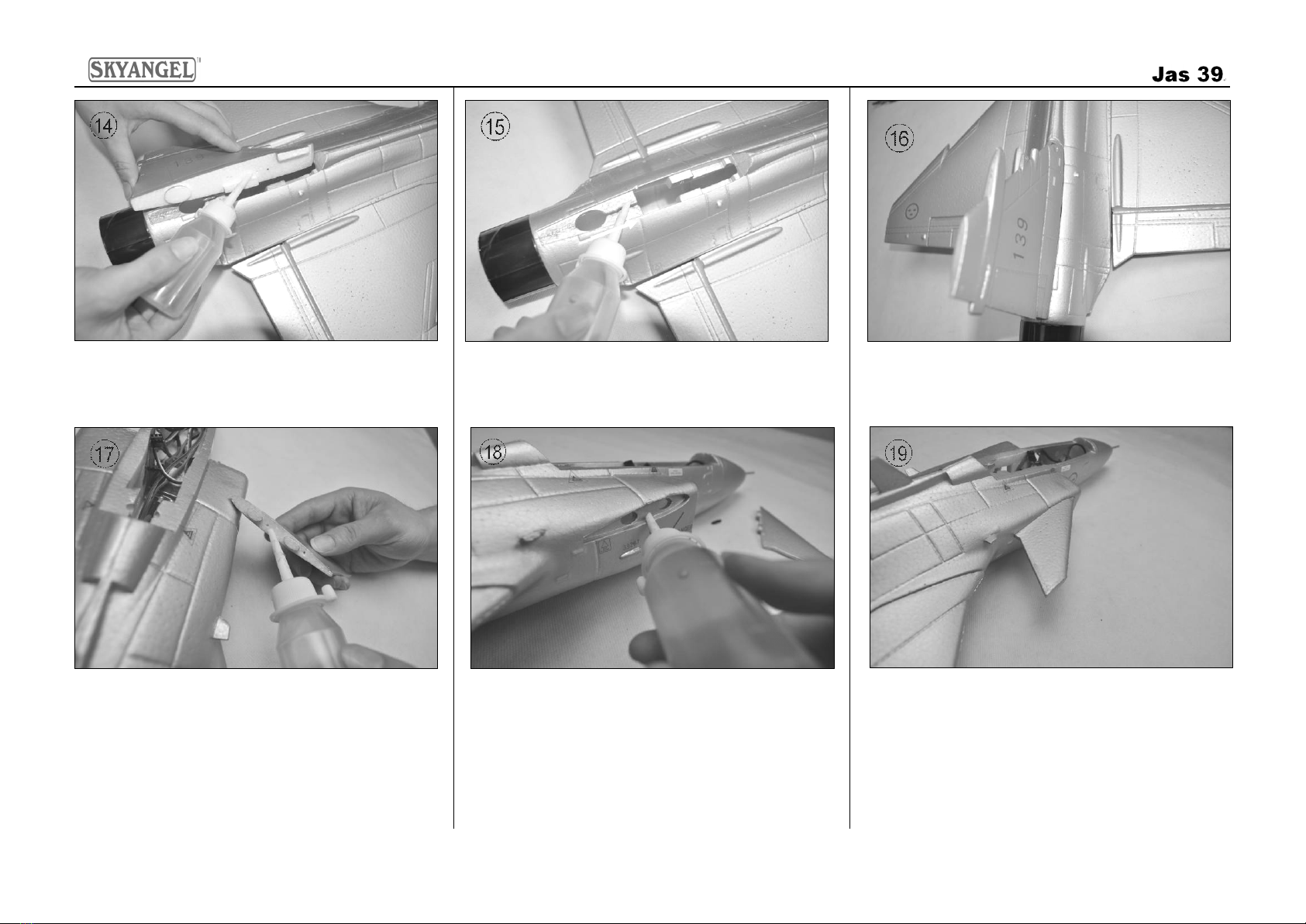
Glued
Glued
Glued
Glued joints,
joints,
joints,
joints, suitable
suitable
suitable
suitable adhesives
adhesives
adhesives
adhesives
Foam safe epoxy is recommended and available
from most reputable model retail shops.
Trial-fit all parts “ dry ” before applying glue.
Follow the recommended curing time suggested
by the glue manufacturer. Allow the glue to fully
cure (harden) to the point where the joint can be
placed under stress.
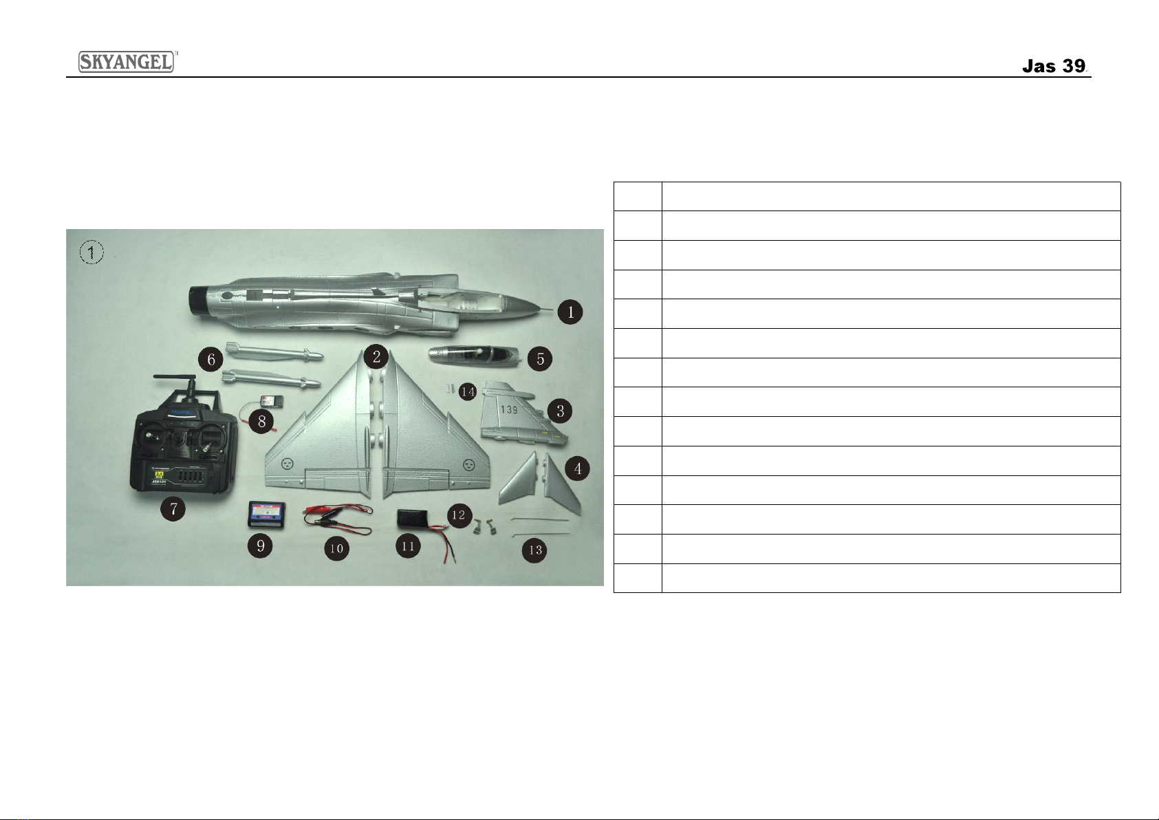
Kit
Kit
Kit
Kit contents
contents
contents
contents
Fuselage, with motor, electronic speed controller
and servo
Clear canopy and cockpit
Left / right wing panels with ailerons
Left / right canard with elevators
V
ertical fin
Accessories
1 x Li-Po battery, 11.1V 850 mAh 20 C
1 x 20
A
Brushless ESC (Electronic Speed Controller)
Assembly
Assembly
Assembly
Assembly and
and
and
and Operating
Operating
Operating
Operating Manual
Manual
Manual
Manual
3
3
3
3
Fig.
Fig.
Fig.
Fig. 1
1
1
1Open the box and check all the parts.
Parts
Parts
Parts
Parts Illustration
Illustration
Illustration
Illustration
Part
Part
Part
Part s
s
s
s List
List
List
List
NO.
NO.
NO.
NO. Description
Description
Description
Description
1 Fuselage
2 Integral wing panels
3
Tail
Set - One
V
ertical Fin
4 Canard
5 Cockpit Canopy
6 Missiles
7 Radio Control Transmitter ( w e highly recommend 2 .4 G Hz system )
8 Receiver
9-10 Balance C harger
11
850 Ah 11.1V 20C Li- P o Battery
12 Control rods Set
13 Push rods Set
14 Mommutator segments
Assembly
Assembly
Assembly
Assembly and
and
and
and Operating
Operating
Operating
Operating Manual
Manual
Manual
Manual
4
4
4
4
Fig.
Fig.
Fig.
Fig. 2
2
2
2- Glue the control rod to horizontal
stabilizers (glue not included).
Fig.
Fig.
Fig.
Fig. 5
5
5
5- Connect the push rods to the aileron servo
arm and control horns.
Fig.
Fig.
Fig.
Fig. 3
3
3
3- Remove any excess glue and hold in
position until glue sets. The p hoto shows the
fi nished view.
Fig.
Fig.
Fig.
Fig. 6
6
6
6- Photo shows the finished view after all
push rods assembled.
.
.
.
.
Fig.
Fig.
Fig.
Fig. 4
4
4
4- Reverse the procedure to the left side.
T he photo show s the finished view.
Fig.
Fig.
Fig.
Fig. 7
7
7
7– Turn up 6-7mm of the rudder.
Assembly
Assembly
Assembly
Assembly and
and
and
and Operating
Operating
Operating
Operating Manual
Manual
Manual
Manual
5
5
5
5
Fig.
Fig.
Fig.
Fig. 8
8
8
8- Reverse the procedure to the right side.
T he photo show s the finished view.
Fig.
Fig.
Fig.
Fig. 11
11
11
11 – Thread the servo lead through the
fuselage
Fig.
Fig.
Fig.
Fig. 9
9
9
9- Apply glue to the wing set.
Fig.
Fig.
Fig.
Fig. 12
12
12
12 -
-
-
-Remove any excess glue and hold in
position until glue sets. The photo shows the
finished view.
Fig.
Fig.
Fig.
Fig. 10
10
10
10 - Apply glue to the fuselage .
Fig.
Fig.
Fig.
Fig. 13
13
13
13 -
-
-
-Reverse the procedure to the right side.
T he photo show s the finished view.
Assembly
Assembly
Assembly
Assembly and
and
and
and Operating
Operating
Operating
Operating Manual
Manual
Manual
Manual
6
6
6
6
Fig.
Fig.
Fig.
Fig. 14
14
14
14 - Apply glue to the vertical fin
Fig.
Fig.
Fig.
Fig. 17
17
17
17 – Apply glue to the canard.
Fig.
Fig.
Fig.
Fig. 15
15
15
15 - Apply glue to the fuselage.
Fig.
Fig.
Fig.
Fig. 18
18
18
18 –
–
–
–Apply glue to the fuselage.
Fig.
Fig.
Fig.
Fig. 16
16
16
16 - The p hoto shows the fin ished view after
glu ing t he vertical fin in place . .
Fig.
Fig.
Fig.
Fig. 19
19
19
19 -
-
-
-The p hoto shows the fin ished view after
glu ing t he canard in place .
Assembly
Assembly
Assembly
Assembly and
and
and
and Operating
Operating
Operating
Operating Manual
Manual
Manual
Manual
7
7
7
7
Fig.
Fig.
Fig.
Fig. 20
20
20
20 - Reverse the procedure to the left side the
p hoto shows the fin ished view
Fig.
Fig.
Fig.
Fig. 23
23
23
23 – Remove any excess glue and hold in
position until glue sets. The photo shows the
finished view.
Fig.
Fig.
Fig.
Fig. 21
21
21
21 –
–
–
–Apply glue to the missiles
Fig.
Fig.
Fig.
Fig. 24
24
24
24 - Photo shows the finished view after
missiles are assembled.
Fig.
Fig.
Fig.
Fig. 22
22
22
22 –
–
–
–Apply glue to the wing set.
Fig.
Fig.
Fig.
Fig. 25
25
25
25 – Apply glue to the commutator
segments
Assembly
Assembly
Assembly
Assembly and
and
and
and Operating
Operating
Operating
Operating Manual
Manual
Manual
Manual
8
8
8
8
Fig.
Fig.
Fig.
Fig. 26
26
26
26 - Glue the commutator segments into the
vertical fin. Photo shows the finished view,
Fig.
Fig.
Fig.
Fig. 29
29
29
29 -
-
-
-Connect channel wire to the receiver..
Fig.
Fig.
Fig.
Fig. 27
27
27
27 -
-
-
-Reverse the procedure to the right side
the photo shows the finished view
Fig.
Fig.
Fig.
Fig. 30
30
30
30 -
-
-
-Photo shows battery leads connected to
the speed controller.
Fig.
Fig.
Fig.
Fig. 28
28
28
28 -
-
-
-Locate the battery in front of the fuselage.
Fig.
Fig.
Fig.
Fig. 31
31
31
31 -
-
-
-The canopy is held in place by magnets
and can be lifted off.
Assembly
Assembly
Assembly
Assembly and
and
and
and Operating
Operating
Operating
Operating Manual
Manual
Manual
Manual
9
9
9
9
Fig.
Fig.
Fig.
Fig. 32
32
32
32 -
-
-
-Photo shows the finished view after
canopy is assembled.
Fig.
Fig.
Fig.
Fig. 33
33
33
33 -
-
-
-Please note turn up 6-7mm of the rudder
before you start to fly your model at the first time.
33
33
33
33
Assembly
Assembly
Assembly
Assembly and
and
and
and Operating
Operating
Operating
Operating Manual
Manual
Manual
Manual
10
10
10
10
Fig.
Fig.
Fig.
Fig. 34
34
34
34 - Charge the flight battery; connect the Equalizer lead
using an d adapter lead matching your charger (adapter lead not
included)
Fig.
Fig.
Fig.
Fig. 35
35
35
35 - Switch the transmitter on, and move the throttle stick to
the “ Motor OFF ” position. (Diagram MODE 1 right throttle control
stick)
34
34
34
34
35
35
35
35
37
37
37
3736
36
36
36