manuals.online logo
Brands
  1. Home
  2. •
  3. Brands
  4. •
  5. SkyLink
  6. •
  7. Receiver
  8. •
  9. SkyLink UR-100 User manual

SkyLink UR-100 User manual

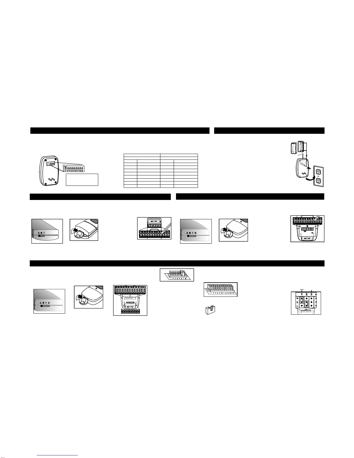
1. Disconnect thepowerfrom
your existing garage door
opener to avoid triggering
the door accidentally dur-
inginstallation.
2. Open your existing wall
mountedgaragedoor
openerbutton.
3. Connect the wires to the
terminals and tighten as
shown.Ifyouropener has
more than two terminals,
attach the wire to the same
twoterminals that thewire
The Universal receiver works with Skylink remote transmitters
model #66, #66C,#36, #36C, #68, #68C,#68B, #68G, #68R,
#88, #88C, #88P. Use a paper clip to set the receiver DIP
switches to match your Skylink transmitter. Each switch of the
receiver has 2 positions (“ON” or “OFF”).
WARNING: Unplug the
receiverbeforechang-
ingcode setting.
PROGRAMMING THE RECEIVER
DIP
SWITCHES
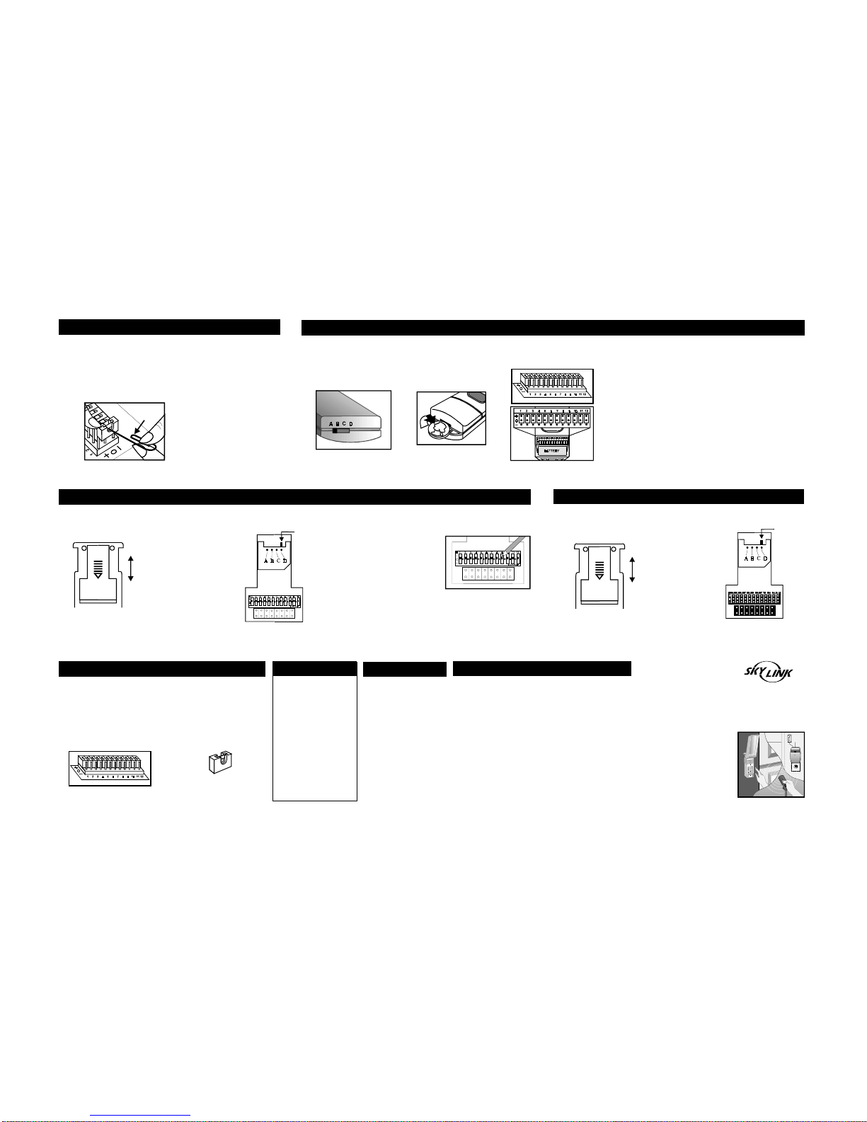
5. The code connector (see dia-
gram J) has 12 rows of posts,
each rows has 3 posts. Each
PROGRAMMING THE SKYLINK MODEL #66, 66C
1. Locate frequency switch
on the top of the trans-
mitterand set to position
A. (See diagram A)
2. To program the model
#66, #66C, open the
case with a coin. (See
diagram B)
Diagram A Diagram B
3. Use a pen or paper clip
to set thecorresponding
DIP switchesnumbered
1 through 9 so that the
switches on the trans-
mitter match those on
thereceiver.Each switch
of the transmitter has 3
positions (“ + ”, “ 0 ”,
“ - ”). To operate with
Skylink #UR-100, only
set the switches to “ + ”
or “ 0 ”. Do not use “ - ”
position.Leave the re-
maining DIP switches in
DIP Switch Location
1. Locate frequency switch
on the top of the trans-
mitter to position A.
(See diagram D)
2. To program the model
#36, #36C, open the
case with a coin. (See
diagram E)
Diagram D Diagram E
INSTALLATION
DO NOT REMOVE ANY
WIRES.
Replace button casing.
4. Plug in the wires to the
receiveras shown.Then,
plug in the receiver to an
electricaloutlet.
5. Re-connect the power to
yourgaragedooroperator.
6.Press the wall button to
test and check wiring for
RECEIVER
Existing wall
mounted button
ANTENNA
from the garage door
openeris connectedto.
PROGRAMMING THE SKYLINK MODEL #36, 36C
4. Test the transmitter with
the Universal receiver.
DIP Switch Location
4. Test the transmitter with
the Universal receiver.
properoperation.
Diagram C Diagram F
UNIVERSAL RECEIVER #UR100 SKYLINK TRANSMITTER
DIP SWITCH POSITION SETTING DIP SWITCH POSITION SETTING
1 ON / OFF 1 + OR 0
2 ON / OFF 2 + OR 0
3 ON / OFF 3 + OR 0
4 ON / OFF 4 + OR 0
5 ON / OFF 5 + OR 0
6 ON / OFF 6 + OR 0
7 ON / OFF 7 + OR 0
8 ON / OFF 8 + OR 0
9 ON / OFF 9 + OR 0
DIP switch setting to match with Skylink Universal Receiver and Skylink Transmitter
Refer to the chartbelow. If any of the DIP switches in the Universal Receiver
are set to “ON” position,set the switches in the Skylink transmitter to the “+”
position. If DIP switches on the Universal Receiverareset to“OFF” position,
set the switches in the Skylink transmitter to the “0” or central or blank position.
the transmitter at “0” or
the center position. (See
diagram C)
3. Use a pen or paper clip
to set thecorresponding
DIP switchesnumbered
1 through 9 so that the
switches on the trans-
mitter match those on
thereceiver.Each switch
of the transmitter has 3
positions (“ + ”, “ 0 ”,
“ - ”). To operate with
Skylink #UR-100, only
set the switches to “ + ”
or “ 0 ”. Do not use “ - ”
position.Leave the re-
maining DIP switches in
the transmitter at “0” or
the center position. (See
diagramF)
1. Locate frequency switch
on the top of the trans-
mitter and set to position
A. (See diagram G)
Diagram G Diagram H
2. To program the model
#38,#38C, open the
case with a coin. (See
diagram H)
3. The transmitter contains 8
brand jumpers (see dia-
gram I) and 12 code con-
nectors. (See diagram J).
Code connector Location
12345678
Brand Jumper
4. The brand jumper has 8 rows
of posts, each row has 2 posts.
(seediagram I). Theconnec-
tor, (see diagram K), must be
placed to the position ‘ 7 ’.
Diagram I
Diagram K
Diagram J
To operate with Skylink #UR100,
only set to “ + ”or “ 0 ” position.
Do not place the connector to
the middle & bottom posts “ - ”
position.
When removing a connector to
set a row to the neutral position,
save the connector in case you
change the code at a later date.
row contains one connec-
tor (see diagram K) for a
total of 12 connectors.
PROGRAMMING THE SKYLINK MODEL #38, #38C
If the connector is placed on the top and middle posts, that
row is set on “ + ” or “ON”. If the connector is removed com-
pletely, (not placed on any posts), it is set to “ 0 ” or the neu-
tral position. (see diagram L for examples of how to set a row
to the three different positions).
‘+’ OR ‘ON’ ‘0’ = BLANK
Diagram L
1. Locate frequency switch
on the top of the trans-
mitter andset to position
A. (See diagram N)
2. To program the model
#68,#68C, #68B,#68G,
#68R, open the case
with a coin. (See dia-
gram O)
Diagram N Diagram O
4. Use an opened paper clip to set the connectors numbered
1 through 9 so that the switches on the transmitter match
those on the receiver. To operate with Skylink #UR100, only
set to “ + ” or “ 0 ” position. Do not place the connector to
the middle & bottom posts “- ”position. Leave the remaining
posts at “ 0 ”, or the blank position (remove the connectors).
See the Diagram J for details.
3. The transmitter has 12 rows
of posts, each row has 3
posts. (see diagram P)
Diagram P
5. Test the transmitter with the Universal receiver.
6. To move the connectors, slide an
opened paper clip into the side of
aconnector and lift. (see diagram
M) When repositioning connec-
tors,place a connector on the two
chosen posts, then pushdown on
theconnector with your finger.
Diagram M
7. Set the connectors num-
bered 1 through 9 so that
the switches on the trans-
mitter match those on the
receiver. Leave the re-
maining posts at “ 0 ”,or
theblank position (remove
the connectors). See the
diagram J for details.
8. Test the transmitter with
the Universal receiver.
Paper
Clip
CLOSE
1. To Program Your Keypad
- Open the cover on the
back. (See diagram Q)
OPEN
2. Set brand jumper by moving the red plastic
tab to the number 7 jumper. Slideanopened
paper clip into the
top of the red plastic
tab, then lift andre-
position.
Frequency
Switch
DIP Switch Location
12 345678
Brand Jumper
3. Set the frequency
switchlocatedabove
to “ D ” position (slide
the switch as far
right as possible).
(See diagram R) 5. Refer to the keypad manual
totest the transmitterwith
theUniversalreceiver.
DIP Switch
Location CLOSE
1.To Program Your Keypad
- Open the cover on the
back. (See diagram T)
OPEN
Frequency
Switch
Brand Jumper
Diagram W
Diagram V
PROGRAMMING THE SKYLINK MODEL #88, #88C
PROGRAMMING THE SKYLINK MODEL #88p
Diagram Q Diagram T
Diagram R
Diagram S
Diagram U
12 345678
FCC
The Universal Garage Door
RemoteControl isapproved
by the FCC and it complies
with Part 15 of the FCC
Rules. Its operation is
subject to the following two
conditions :
1. This device may not
cause harmful inter-
ference.
2. This device must accept
anyinterference that
may cause undesired
operation.
Skylink will not be held liable
or responsible for
any misuse or application
of this product other than
for its intended use.
GARAGE DOOR/
GATE OPENER
UNIVERSAL RECEIVER
USER'S INSTRUCTIONS
(Model UR-100)
®areregistered trademarksoftheirrespectivecorporations
SKYLINK
TECHNOLOGIES INC.
2213 Dunwin Drive,
Mississauga, Ontario
L5L 1X1, CANADA
(905)608-9223
(905)608-8744 FAX
Email:[email protected]
(Reply within 24 hrs)
Customer Service : (800)304-1187
http://www.skylinkhome.com
P/N. 101A111-003 Rev.3
Patent no. 382251
Patents Pending
©1999 SKYLINK TECHNOLOGIES INC.
WARNING:
Changes or modifications
to this unit not expressly
approved by the party res-
ponsible of compliance
could void the user’s
authority to operate the
equipment.
WARNING
DO NOT let children
use any garage door
transmitter without
adult supervision.
Children can injure
themselves or others
by the garage door.
WARRANTY
If,within one year from date
of purchase, this product
should become defective
(except battery), due to
faulty workmanship or
materials,it will be repaired
orreplaced,without charge.
Proof of purchase is
required.
®
4. Use a pen or paper clip
to set the corresponding
DIP switchesnumbered
1 through 9 so that the
switches on the trans-
mitter match those on
thereceiver.Eachswitch
of the transmitter has 3
positions (“ + ”, “ 0 ”,
“ - ”). To operate with
Skylink #UR-100, only
set the switches to “ + ”
or “ 0 ”. Do not use “ - ”
position.Leave the re-
maining DIP switches in
the transmitter at “0” or
the center position. (See
diagram S)
5. Refer tothe keypad manualto test thetransmitter with the Universal
receiver.
4. The connector (See diagram V) has 12 rows ofposts, each row
has 3 posts. Each row contains one connector (See diagram
W). Set the code connectors from number 1 through 9 so that
the switches on the transmitter match those on the receiver.
To operate with #UR100, only set the connectors to “ + ” or “0”
(blank position). Do not set the connectors to “ - ” position.Leave
the remaining posts at “ 0 ”, or the blank position (remove the
connectors). See the diagram L for details.
2. Set brand jumper by moving the red plastic
tab to the number 7 jumper. Slide an opened
paper clip into the
top of the red plastic
tab, then lift andre-
position.
3. Set the frequency
switchlocatedabove
to “ D ” position
(slide the switch
as far right as
possible). (See
diagram U)
PROGRAMMING THE SKYLINK MODEL #38, #38C PROGRAMMING THE SKYLINK MODEL #68, #68C, #68B, #68G, #68R
Code connector Location
PROGRAMMING THE SKYLINK MODEL #88p

Other SkyLink Receiver manuals

SkyLink SMART BUTTON GB-318 Guide User manual

SkyLink

SkyLink SMART BUTTON GB-318 Guide User manual

SkyLink SkylinkHome Smart Button GB-434 User manual

SkyLink

SkyLink SkylinkHome Smart Button GB-434 User manual

SkyLink MR3R User manual

SkyLink

SkyLink MR3R User manual

SkyLink UR-100 User manual

SkyLink

SkyLink UR-100 User manual

SkyLink MZ-104 User manual

SkyLink

SkyLink MZ-104 User manual

SkyLink WIRELESS SWITCH SW-18 User manual

SkyLink

SkyLink WIRELESS SWITCH SW-18 User manual

SkyLink GTR User manual

SkyLink

SkyLink GTR User manual

SkyLink SW-18R User manual

SkyLink

SkyLink SW-18R User manual

SkyLink 318R User manual

SkyLink

SkyLink 318R User manual

SkyLink Household Alert GM-318R User manual

SkyLink

SkyLink Household Alert GM-318R User manual

SkyLink 18R User manual

SkyLink

SkyLink 18R User manual

SkyLink MZ-52 User manual

SkyLink

SkyLink MZ-52 User manual

SkyLink R4G User manual

SkyLink

SkyLink R4G User manual

SkyLink Household Alert GM-433R Manual

SkyLink

SkyLink Household Alert GM-433R Manual

Popular Receiver manuals by other brands

Yamaha RX-V377 owner's manual

Yamaha

Yamaha RX-V377 owner's manual

Vemco VR2C user manual

Vemco

Vemco VR2C user manual

Celabs HD100AQ Specifications

Celabs

Celabs HD100AQ Specifications

TaoTronics TT-BR010 user guide

TaoTronics

TaoTronics TT-BR010 user guide

Univers by FTE U4127 user manual

Univers by FTE

Univers by FTE U4127 user manual

Hi-Tec Aurora 9 manual

Hi-Tec

Hi-Tec Aurora 9 manual

Integra DTR-80.1 instruction manual

Integra

Integra DTR-80.1 instruction manual

Pioneer VSX-9100TX operating instructions

Pioneer

Pioneer VSX-9100TX operating instructions

Strong SRT 6011 user manual

Strong

Strong SRT 6011 user manual

Kathrein UFS 900sw operating manual

Kathrein

Kathrein UFS 900sw operating manual

Pira P275R user guide

Pira

Pira P275R user guide

Niles ZR-6 brochure

Niles

Niles ZR-6 brochure

WisyCom MCR41 user manual

WisyCom

WisyCom MCR41 user manual

Datalogic SD9030 Quick reference guide

Datalogic

Datalogic SD9030 Quick reference guide

Samsung SWA-4000 Service manual

Samsung

Samsung SWA-4000 Service manual

Veripos LD8 Operation manual

Veripos

Veripos LD8 Operation manual

Denon AVR-3803 Control protocol

Denon

Denon AVR-3803 Control protocol

Topfield TF-S3000CHD quick guide

Topfield

Topfield TF-S3000CHD quick guide

manuals.online logo
manuals.online logoBrands
  • About & Mission
  • Contact us
  • Privacy Policy
  • Terms and Conditions

Copyright 2025 Manuals.Online. All Rights Reserved.