SKYLUX ClimaCar User manual
CARPORT
ClimaCar
®
Mounting instructions
EN
Art.N° 49579

E_MH_Mounting_instructions_Skylux_ClimaCar 01/04/2019
2/32
CONTENT p. 2
OVERVIEW CLIMACAR PROFILES AND PARTS p. 3 - 4
GENERAL INSTALLATION TIPS p. 5
DIMENSIONS p. 6 - 7
PREPARATION p. 8 - 9
EXAMPLE DRAWING CLIMACAR p. 10
POSTS WITH POST SUPPORT p. 11 - 12
POSTS IN CONCRETE p. 13 - 14
SUPPORTS p. 15- 16
RECTANGULAR PROFILES 72 X 110 p. 17
RECTANGULAR PROFILES 35 X 35 p. 18
INSTALLATION SUBSTRUCTURE p. 19 - 21
INSTALLATION GUTTERS G120A p. 22
INSTALLATION SUPERSTRUCTURE p. 23 - 27
FINISH p. 28 - 29
Table of contents
01/04/2019 3/32
E_MH_Mounting_instructions_Skylux_ClimaCar
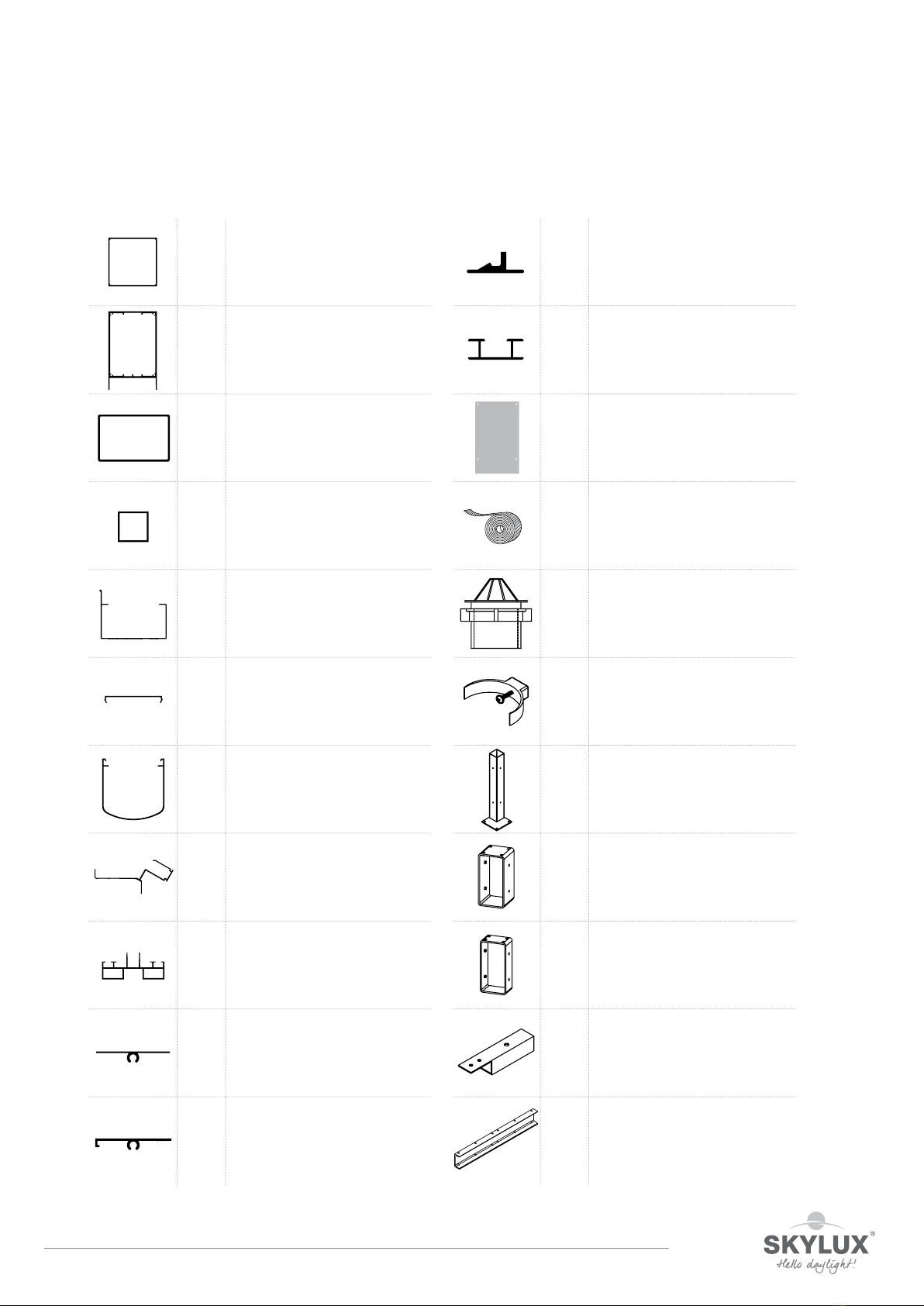
Overview ClimaCar profiles and parts
PGDX POST 110/110
GDX SUPPORT
P72 RECTANGULAR PROFILE 72 x 110
LP08 RECTANGULAR PROFILE 35 x 35
G120A GUTTER
PCB72 POST CLIP BASE (OPTIONAL)
PC72 POST CLIP (OPTIONAL))
LP836 BASE PROFILE
LP533 LOWER ARCH
LP502 LOWER ARCH
LP512 LATERAL UPPER ARCH
LP505 DRAFT STIP
GDGL RIDGE CONNECTION PROFILE
GDSX END PLATE FOR SUPPORT GDX
TAPE SYNTHETIC TAPE ALU
GC OUTLET + SWIVEL ø 80 MM
412 BRACKET FOR DRAINPIPE
PS
POST SUPPORT
C110
BRACKET FOR PGDX
C72
BRACKET FOR P72
GT35
BRACKET FOR LP08
UPN140
CONNECTION PROFILE

E_MH_Mounting_instructions_Skylux_ClimaCar 01/04/2019
4/32
Overview ClimaCar profiles and parts
PT110
REINFORCEMENT PLATE
G120AS
END PIECE FOR GUTTER
BOLT
M10x30 BOLT M10 X 30 GALVANISED
Washer
M10 WASHER M10 GALVANISED
SCR
5,8x38 SELF-DRILLING SCREW
ZSB
ZSG
SELF-DRILLING SCREW INOX
SELF-DRILLING SCREW LACQUERED
BOUT
M8x60 BOLT M8 X 60 INOX HEXGONAL
BOLT
M8x20 BOLT M8 X 20 INOX SOCKET
BOLT
M10 x
180
BOLT M10 X 180 INOX SOCKET
51197
51819
COUNTERSINK DRILL Ø 16,5 MM
COUNTERSINK DRILL Ø 20,5 MM
Washer
M8 WASHER M8 INOX
NUT
M8 NUT M8 GALVANISED
ZSR ANCHOR BOLT HSA 8/75
UGS
WUGS
UNIVERSAL GUTTER SPOUT +
SWIVEL GUTTER SPOUT
411 DRAINPIPE + SLEEVE ø 80 MM
414 CURVE 87° WITH SLEEVE ø 80 MM

01/04/2019 5/32
E_MH_Mounting_instructions_Skylux_ClimaCar
General installation tips
Please read this manual carefully.
The installation must be carried out by people with sucient technical knowledge and experience in conservatory installation.
The installer must take the required safety measures into account during installation such as the use of scaolding and
personal protective equipment (safety shoes, helmet, gloves, safety goggles, etc.) to ensure the work is carried out in a
safe environment. During installation, the necessary precautions must be taken to ensure the stability of the unfinished
construction.
Fixing material
The selection of required fixing material is dependent on the foundation or the walls. Check whether the foundation and
the walls on which the structure is to be anchored have a sucient load-bearing capacity. The installer is responsible for the
assessment of the appropriate fixing materials for the load and foundation on which the structure is to be fixed. Please contact
your fixing material supplier or specialised engineering consultants in case of doubts. Skylux cannot be held liable for the
installation or the fixing materials used.
Static (Statik)
All guidelines and parts mentioned in this manual must be used and applied correctly to comply with the Static (Statik).
Polycarbonate plastic sheets
Only use polycarbonate sheets of Skylux. These sheets must always be installed with the UV protected side facing upwards.
This “sun side” is always marked on the protective foil. The sheet ends must be taped with the supplied aluminium-coloured
tape. This avoids dust and dirt from entering the sheets. Polycarbonate is not completely damp proof. Condensation in the
channels may occur (physical phenomenon). Avoid using silicone because it can aect the plastic sheets. Plastic sheets can
produce contraction or expansion sounds due to change in temperature. This does not influence the guarantee and is not
accepted as a damage claim.
Conditions and guarantee
The guarantee is no longer valid if the mounting instructions mentioned in this document are not followed. If these
instructions are not respected and/or if other parts are used, this can lead to detrimental consequences for the safety and
durability of the product. Deviations are not allowed without the written permission of the manufacturer. The mounting
instructions are based on our latest level of knowledge and technique. We cannot be held responsible for possibly insucient
information. Always check if our product is suitable for your application. Since the usage and installation of our product is
carried out beyond our control, Skylux cannot be held responsible for possible damage. The installer must take into account
the presented span lengths depending on the glazing and load (snow load or wind load) in accordance with the valid standards.
For out of range carports you can always contact the manufacturer, architect, or study bureau. Technical changes are
reserved to the manufacturer without preceding oral or written notification. Skylux reserves the right to change the mounting
instructions without preceding notification. Changes in the mounting instructions or product changes do not allow for
compensation or exchange of parts. The latest version of this manual can always be consulted on www.skylux.be.
ClimaCarfast
Skylux provides you the free ClimaCarfast calculation application. You will receive information on how to log on and download
the Excel version of the application upon request. ClimaCarfast calculates the price of your ClimaCar roof. For each project,
you will receive an overview of the profiles, lengths, parts, permitted loads, etc. The application provides information and
indications for the user. Skylux reserves the right to change the ClimaCarfast calculation application without prior notification.
The calculation results are indicative and do not allow for compensation. The latest version of the calculation application can
always be downloaded on www.skylux.be.
E_MH_Mounting_instructions_Skylux_ClimaCar 01/04/2019
6/32
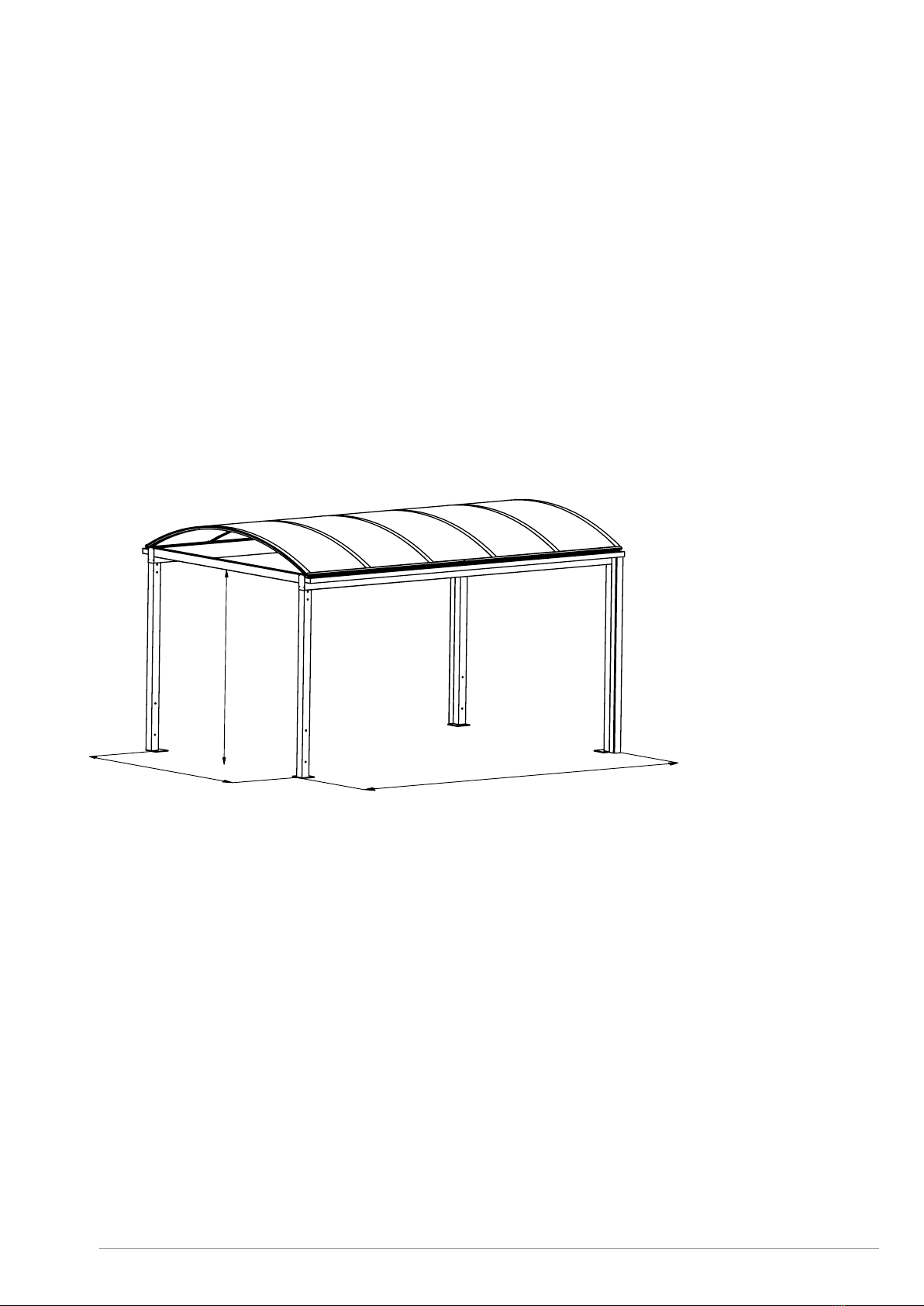
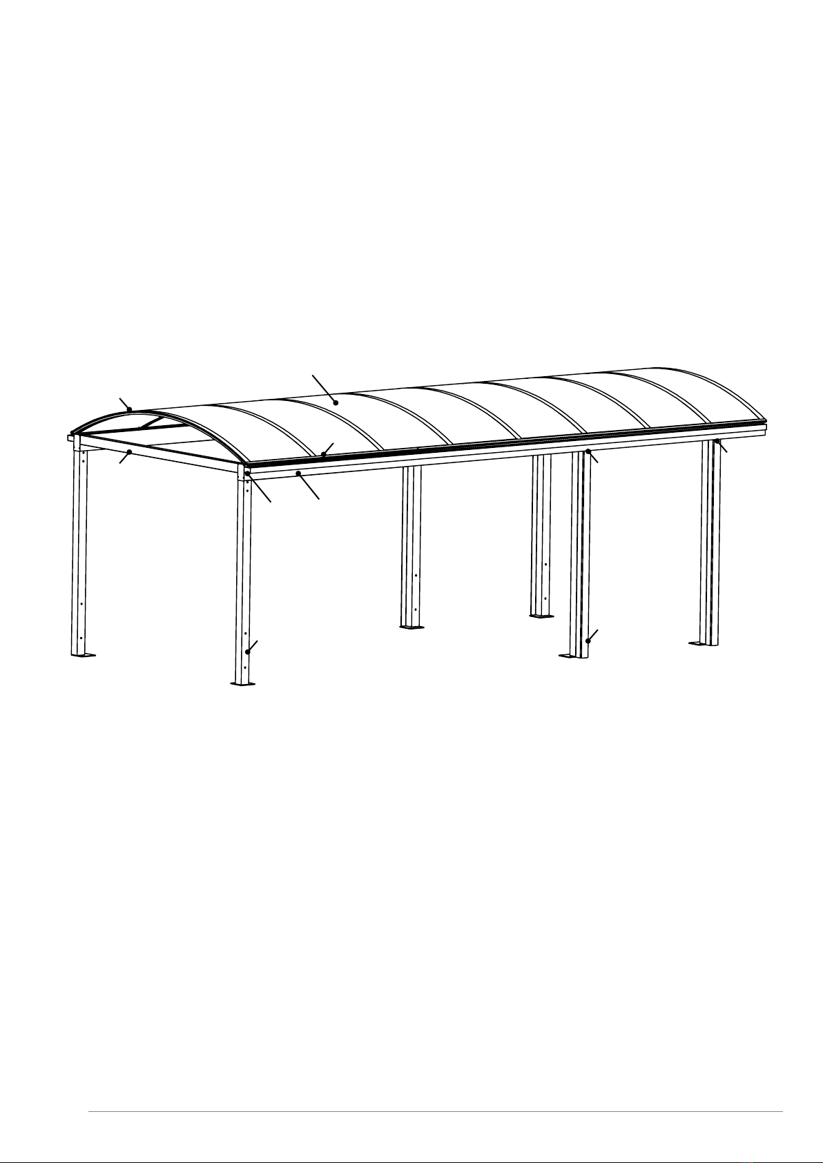
Dimensions
Standard dimensions
Width B: width between the posts (clear width): 3025 of 3500 mm
Depth D: total depth: 5000, 6000, 7000, 8000, …… 45000 mm (per metre)
Height H: height under cross beam (clear height): max 3230 mm
B
H
D

01/04/2019 7/32
E_MH_Mounting_instructions_Skylux_ClimaCar
Bg = B + 467
H
Ht = H + 535/595
Bp = B+220
B = 3025/3500
H - 80
D = min 5000, ... max 45000
D - 220
Ht = H + 535/595
Derived dimensions
BBp Bg
3025 3245 3492
3500 3720 3967
Bp: posts included
Bg: gutters included
B 3025 3500
Ht H + 535 H + 595
Ht: total height
E_MH_Mounting_instructions_Skylux_ClimaCar 01/04/2019
8/32
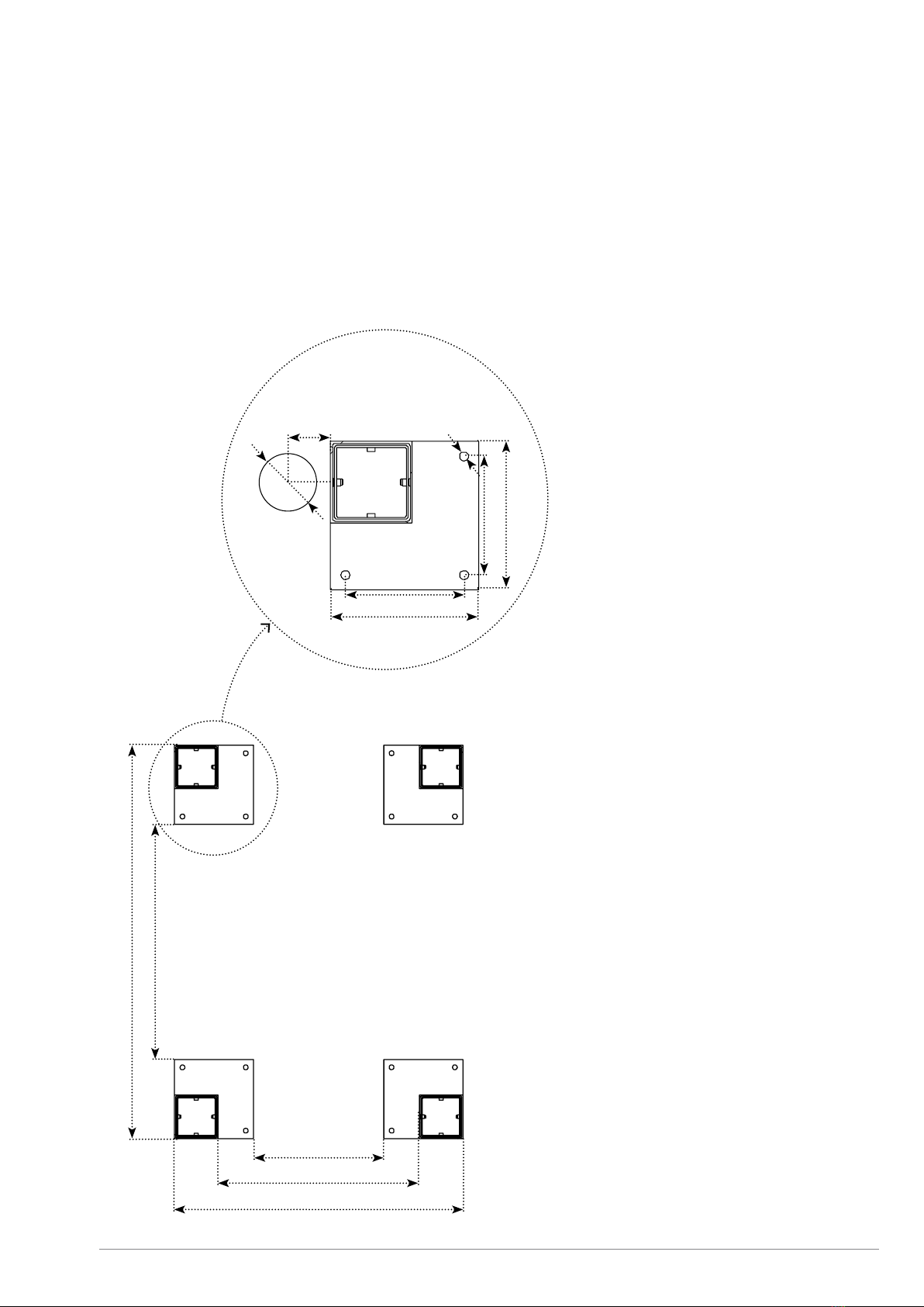
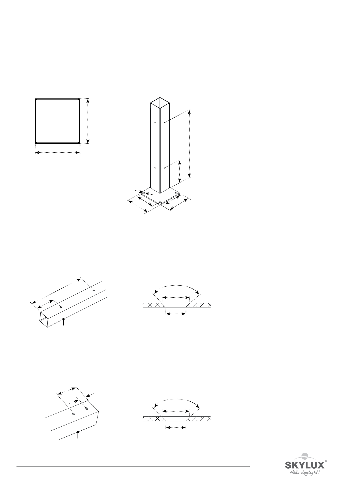
Preparation
1. Installation of the posts on a load-bearing surface
Make sure the surface (foundation) is strong and solid enough for the 4 (corner) posts. The substructure must be
levelled. The gutters are optional. The water drainage can be installed on the front or on the back on the outer side
against the post. Rain water drainage can be provided in the foundation by means of drainpipes.
B - 180
D - 400
D
B + 220
B
160
200
160
200
ø12
60
ø80

01/04/2019 9/32
E_MH_Mounting_instructions_Skylux_ClimaCar
2. Setting posts in concrete
Provide foundation holes of min. 600 x 600 x 800 mm (width x length x height) for the (corner) posts. The
substructure must be perfectly levelled. The gutters are optional. The water drainage can be installed on the front
or on the back on the outer side against the post. Rain water drainage can be provided in the foundation by means
of drainpipes.
60
ø80
600
600
D
D - 220
B + 220
B
E_MH_Mounting_instructions_Skylux_ClimaCar 01/04/2019
10/32
Example drawing ClimaCar
A10 - A11 Posts - Water drainage pg. 11-14, 28
A20 - A21 Supports - Rectangular profiles pg. 15-18
A30 - A31 - A32 Assembly - Gutter pg. 19-22
A40 - A41 - A42 Base profile - Arches - Sheets pg. 23-29
A41
A42
A21
A30
A40
A20
A31
A11
A10
A32
01/04/2019 11/32
E_MH_Mounting_instructions_Skylux_ClimaCar
Posts with post support
PGDX 110/110 PS
Preparation posts (4 X)
The post must be sawn to the right length (H– 59 mm).
Drill a central hole (Ø 11) 200 and 600 mm from the bottom in the 2 opposite sides below. Use a countersink 90°
Ø 16,5 mm (art. 51197) to make the hole conical.
Drill a central hole 50 and 150 mm from the top in the 2 opposite sides above. Use a countersink 90°
Ø 16,5 mm (art. 51197) to make the hole conical. The transparent sticker art. 49566 can be used here as a drilling
stencil.
110
110
200
600
ø12
160
200
160
200
200
600
ø11
ø16,50
90°
PGDX
150
50
ø11
ø16,50
90°
PGDX
E_MH_Mounting_instructions_Skylux_ClimaCar 01/04/2019
12/32
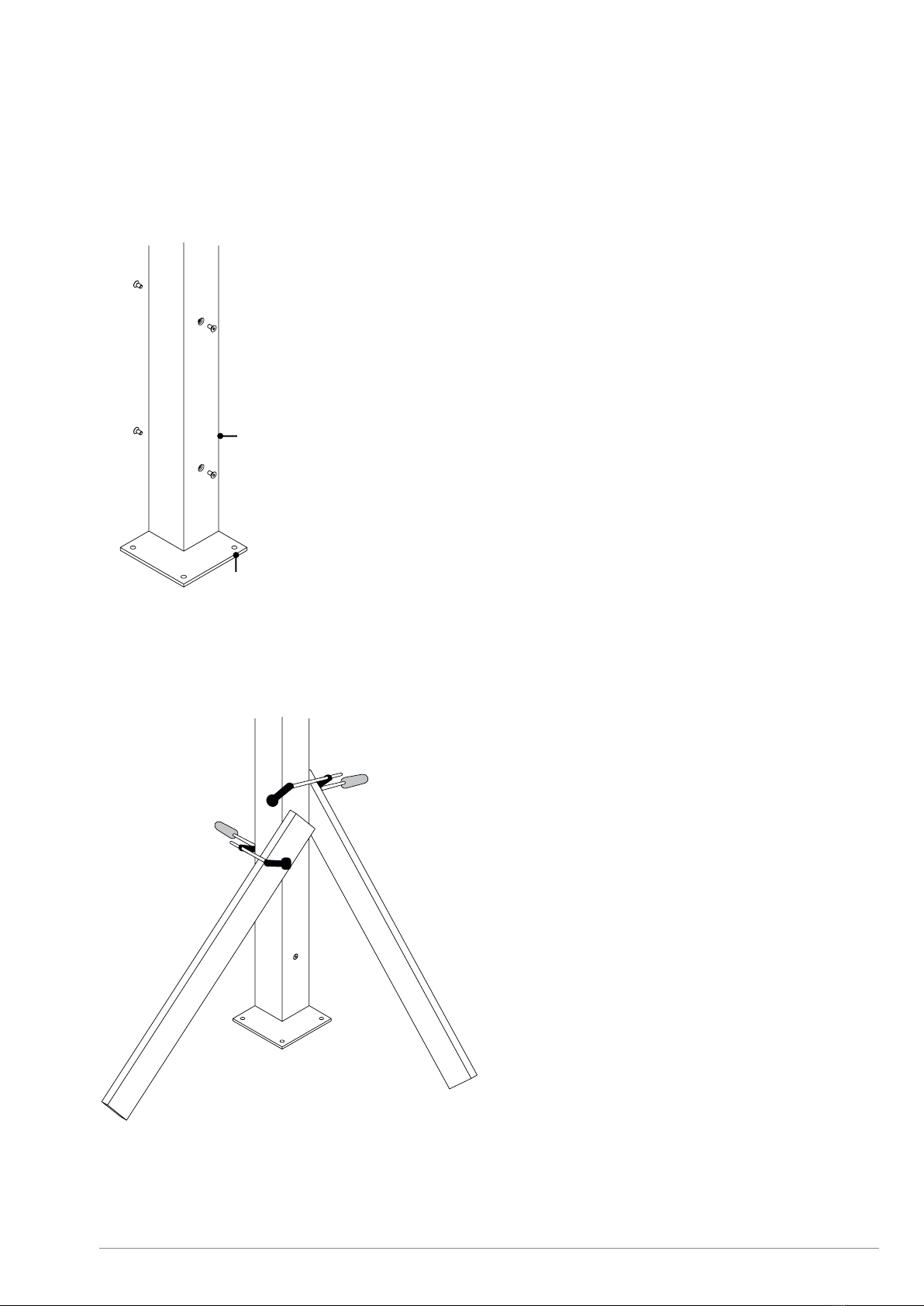
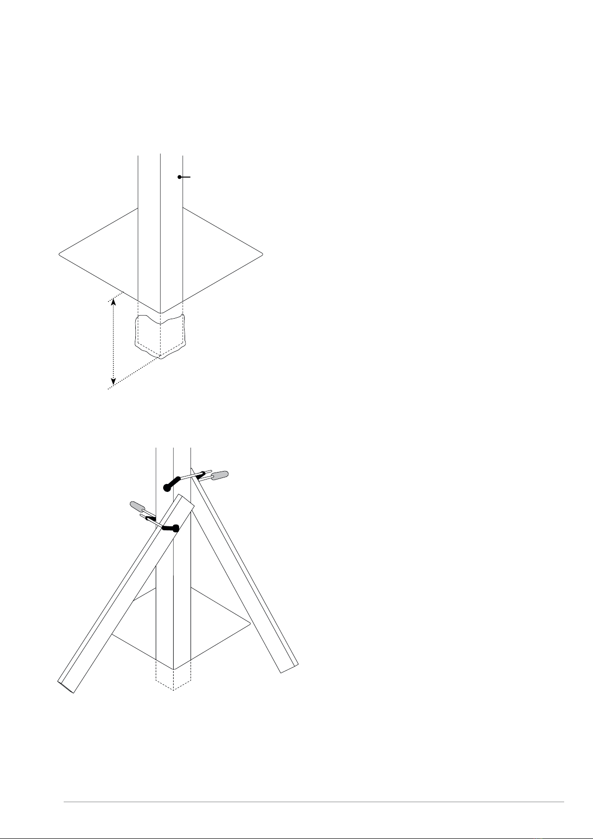
Installing the posts with post support
Slide the posts PGDX over the post support PS and use 4 bolts M8 x 20 to attach the posts on the post support.
Do not tighten the bolts yet.
Put the 4 posts on the corners of the ClimaCar with the support plate facing inwards. Be sure to brace these posts
until the construction is completed.
PS
PGDX
01/04/2019 13/32
E_MH_Mounting_instructions_Skylux_ClimaCar
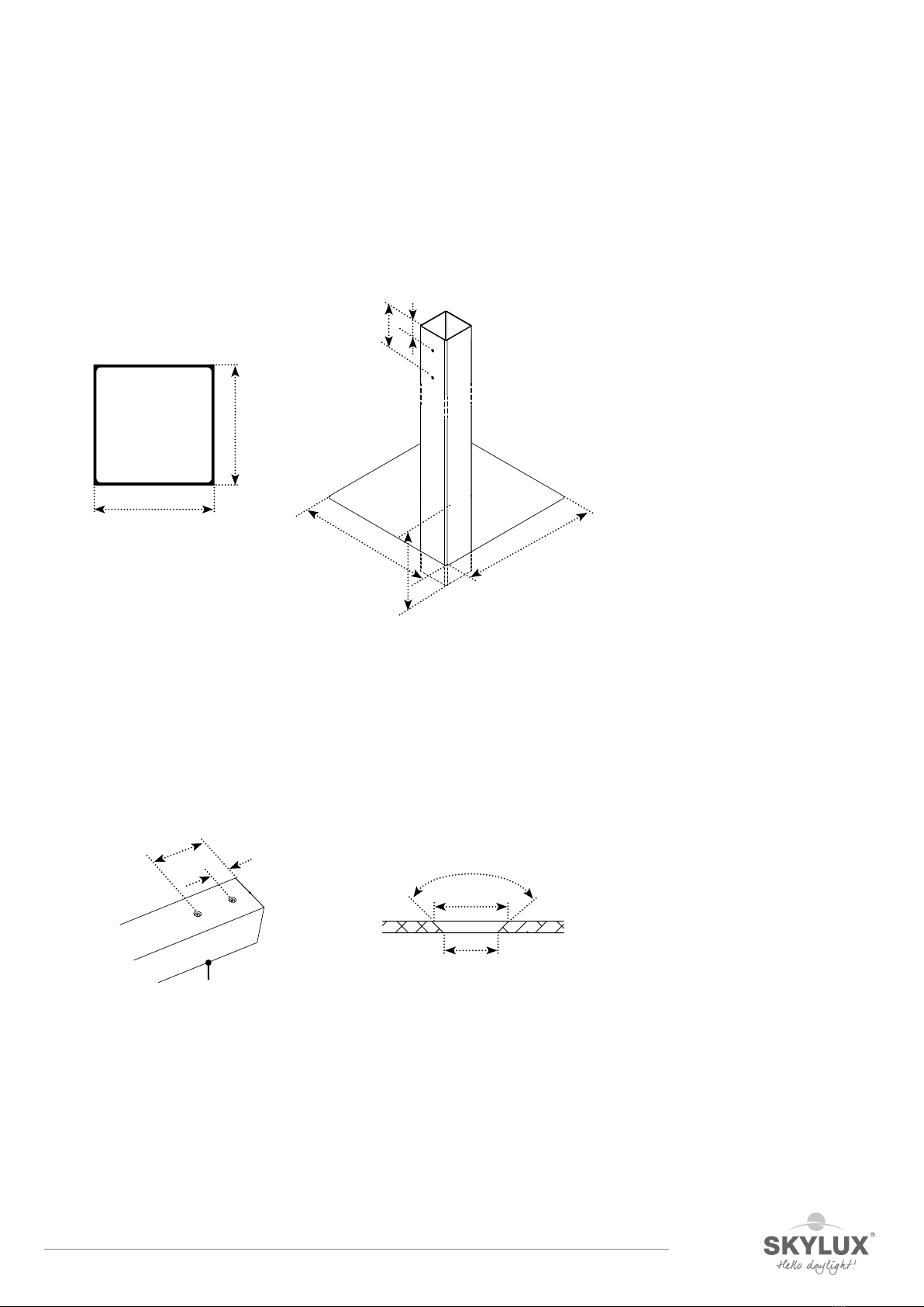
Posts in concrete
PGDX 110/110 PS
Drill a central hole 50 and 150 mm from the top in the 2 opposite sides above. Use a countersink 90° Ø 16,5 mm
(art. 51197) to make the hole conical. The transparent sticker art. 49566 can be used here as a drilling stencil.
110
110
150
50
ø11
ø16,50
90°
PGDX
min. 400
50
600
600
150
E_MH_Mounting_instructions_Skylux_ClimaCar 01/04/2019
14/32
Installing the posts in the foundation
Set all posts in the foundation holes. The post must be at least 40 cm deep. Seal o the opening of the post with
foil to prevent concrete from entering the post. The inside of the post is not protected against the aggressive
eect of concrete.
Install all posts and be sure to brace these posts until the construction is completed.
We advise to brace the subconstruction until it’s completely installed. Afterwards, everything can be levelled and
the foundation holes can be filled with concrete.
PGDX
min. 400

01/04/2019 15/32
E_MH_Mounting_instructions_Skylux_ClimaCar
Supports
GDX C110
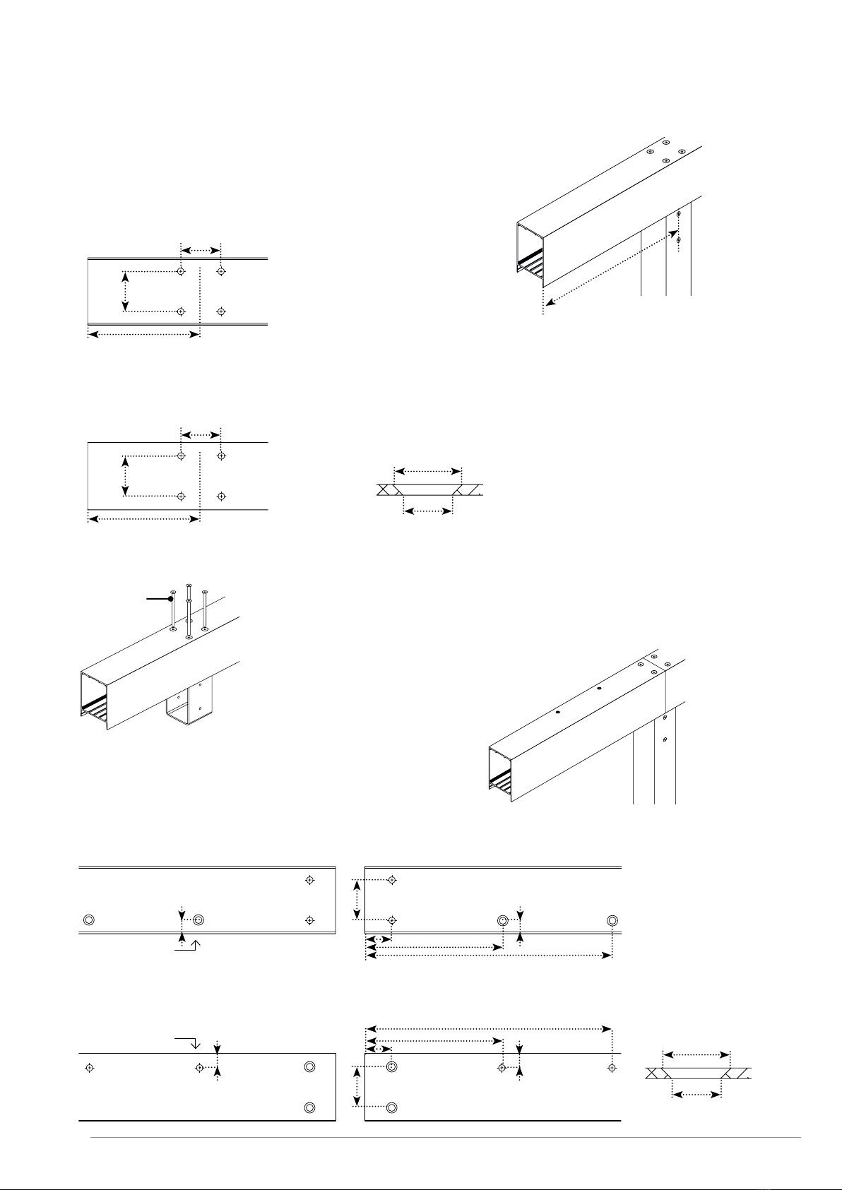
Preparation supports (2 x)
Drill holes for the connection profiles 72 x 110
Check the length of the supports. These are sawn to the correct length. Place the support on its side on trestles.
Drill 4 holes of Ø 11 mm in the ends on the side of the support. These holes are necessary to connect the left and
right supports to each other on the ends by means of the 72 x 110 profile. The transparent sticker art. 49564 can
be used here as a drilling stencil.
Preparation supports for posts
Possibility 1: the post is placed on the extremities or on the corner of the carport
Drill 4 holes of Ø 11 mm in the ends on the bottom side.
The transparent sticker art. 49563 can be used here as a drilling stencil.
Place the brackets C110 on the beam and make sure the holes in the bracket
are faced sideways. Put the reinforcement plate PT110 in the support.
Use the bolts M10 x 30 and the washers M10 to secure the brackets.
Do not tighten the bolts yet.
29
117
190
20 20
70
70
20
ø11
70
20
19
34
GDX
C110
GDX
M10 x 30
+ (4x)
E_MH_Mounting_instructions_Skylux_ClimaCar 01/04/2019
16/32
Possibility 2: the post is not placed on the extremities
Drill 4 holes of Ø 11 mm in the bottom side.
DX is the distance between the edge of the gutter support and the central line
of the post. The transparent sticker art. 49563 an be used here as a drilling stencil.
Next, drill 4 holes Ø 11 mm in the top side of the support. Dx is the distance between the edge of the gutter
support and the central line of the post. The transparent sticker art. 49563 an be used here as a drilling stencil.
Use a countersink 90° Ø 20.5 mm (art. 51819) to make the hole conical.
Place the brackets C110 on the beam and make sure the holes in the bracket re faced sideways. Use the bolts M10
x 180 to secure the brackets. Do not tighten the bolts yet.
Possibility 3: the connection of 2 supports is supported by the post
Drill 2 x 2 holes Ø 14 mm in the bottom side at 35 mm from the edge.
Also drill 2 x 2 holes Ø 11 mm at 250 and 465 mm from the edge. Use a countersink 90° Ø 20.5 mm to make the
hole conical.
Afterwards, drill 2 x 2 holes Ø 11 mm in the top side of the support.
Use a countersink 90° Ø 20.5 mm (art. 51819) to make the hole conical. Drill 2 x 2 holes Ø 14 mm at 250 and 465
mm from the edge.
DX
70
70
Ø 14
Dx
70
70
Ø 11 v 20,5
Dx ø11
ø20,50
M10 x 180
(4x)
ø11
ø20,50
35
Ø 11 v 20,5
70
Ø 14 Ø 14
250
465
Ø 11 v 20,5
inside carport
35
Ø 14
70
Ø 11 v 20,5 Ø 11 v 20,5
250 465
Ø 14
inside carport
20 20
23,5 23,5

01/04/2019 17/32
E_MH_Mounting_instructions_Skylux_ClimaCar
Rectangular profile 72 X 110
P72 C72
Preparation rectangular profile (2 x)
Check the length of the rectangular profiles. These are sawn to a length of 3018 or 3493 mm. Place the profiles
on trestles.
Drill 4 holes of Ø 11 mm in the extremities on the shortest side of the profile. Use a countersink Ø 16.5 mm (art.
51197) to make the holes conical. The transparent sticker art. 49564 can be used here as a drilling stencil.
Slide the brackets C72 into the rectangular profiles and make sure the holes in the bracket are faced outwards.
Use the bolts M8 x 20 to secure the brackets. Do not tighten the bolts yet.
72
110
150
50
50
150
ø12,30
ø16,50
90°
P72
P72
C72

E_MH_Mounting_instructions_Skylux_ClimaCar 01/04/2019
18/32
Rectangular profile 35 X 35
LP08 GT35
Preparation rectangular profile (1x or 2x)
Check the length of the rectangular profiles. These are sawn to a length of 3018 or 3493 mm and pre-drilled on
the ends (Ø 8.5 mm). Place the profile on trestles.
Length of support max. 5000 max. 7000
Number of profiles 1 x 2x
+ an extra rectangular profile for each connection of 2 supports.
Slide the brackets GT35 into the rectangular profiles until the holes in the bracket match the holes in the profiles.
Use the bolts M8 x 60 + washers M8 and nuts M8 to secure the brackets.
35
35
LP08
GT35
M8 x 60

01/04/2019 19/32
E_MH_Mounting_instructions_Skylux_ClimaCar
Installation substructure
Posts
Check the distances between the posts and brace them suciently (see pg. 8 & 9).
Installation supports (2 x)
Place the supports on the posts. Slide the brackets into the posts. The lowest lips of the support slide over the
posts with a press fit. 4 bolts M8 x 20 are screwed in per post.
Post on the extremities
Post further inside
M8 x 20 (4x)
M8 x 20 (4x)

E_MH_Mounting_instructions_Skylux_ClimaCar 01/04/2019
20/32
Post supports connection
Installation rectangular profiles 72 x 110 (2 x)
The rectangular profiles must be mounted on the ends between the supports.
Use 4 bolts M10 x 30 and washers M10 to attach the rectangular profiles to the supports.
M8 x 20 (4x)
M10 x 30 + (4x)
Slide the brackets C110 into the supporting post and
make sure the holes in the bracket are faced sideways.
Use the bolts M8 x 20 to secure the brackets. Do not
tighten the bolts yet.
Place the support on the half of the post. Turn a bolt M10 x
180 into the outermost hole of the support and secure it in
the bracket C110.
Slide the connection profile UPN140 in the support
until the drill hole matches the opening in the
support. Secure the connection profile with M10 x
180.
lide the second support over the connection profile until it
reaches the first support. Put 2 bolts M10 x 180 in the holes
and tighten them in the bracket C110. Now, enter the 4
remaining bolts on the bottom in the support through the
connection profile UPN140. Provide a washer and nut M10
and tighten them.
M10 x 180
M10 x 180
inside
carport
outside
carport
M10 x 180
inside
carport
outside
carport
This manual suits for next models
1
Table of contents
Other SKYLUX Tent manuals


Popular Tent manuals by other brands


TEX VISIONS
TEX VISIONS EVENT TENT BASIC Assembly instructions

Bestway
Bestway 58460 owner's manual

Outdoor Connection
Outdoor Connection ESCAPE 3 PLUS quick start guide

AC Infinity
AC Infinity CLOUDLAB Series user manual

Isotra
Isotra MIRA 4 MEASUREMENT AND ASSEMBLY MANUAL

Khyam
Khyam Cleveland 6 Erection Instructions

Coleman
Coleman NorthStar X4 Setup instructions

Tentsile
Tentsile UNA owner's manual

Ozark Trail
Ozark Trail WMT14168.1 Assembly instructions

MMI OUTDOOR
MMI OUTDOOR TREK TENTS 283A Setup instructions

skandika outdoor
skandika outdoor PALERMO Setup Instruction

Snugpak
Snugpak JOURNEY TRIO Assembly instructions