SKYLUX Climax Panorama User manual
CANOPY
Climax Panorama®
Mounting instructions
Self-supporting aluminium profile system
EN
Art. N° 36183

E_MH_Mounting_instructions_Skylux_Climax_Panorama 01/03/2022
2/68
1 CONTENT
SAFETY p.
GUIDELINES p.
LOAD CAPACITY GRAPHS p.
. GENERAL CONSIDERATIONS p.
. LOAD CAPACITY GRAPHS FOR ROOFS WITH PLASTIC SHEETS p.
.. GUTTER PROFILES p.
.. RAFTER PROFILES p.
. LOAD CAPACITY GRAPHS FOR ROOFS WITH GLASS p.
.. GUTTER PROFILES p.
.. RAFTER PROFILES p.
OVERVIEW INSTALLATION VARIABLES p.
. APPROACH OF MOUNTING INSTRUCTIONS p.
. CODES FOR THE POSITIONING OF THE ELEMENTS p.
. PITCH p.
. FRAME CONNECTIONS p.
. HORIZONTAL BEAMS p.
. ROOF PACKAGE p.
.. ELEMENTS BELOW GLAZING p.
.. ELEMENTS ABOVE GLAZING p.
. GLAZING EDGE PROFILES p.
. POST COVERS p.
MEASURING A WALLSUPPORTED PENT ROOF p.
. OVERVIEW ELEMENT POSITION CODE p.
. MEASURING p.
.. DETERMINE THE MEASUREMENTS p.
MEASURING A FREESTANDING PENT ROOF p.
. OVERVIEW ELEMENT POSITION CODE p.
. HEIGHT & DEPTH p.
.. RIDGE & GUTTER BEAM p.
.. CROSSSECTION OF POSTS p.
. OPTIONAL GROUND FOUNDATION p.
MEASURING A WALLSUPPORTED GABLE ROOF p.
. DETERMINE THE MEASUREMENTS p.
OVERVIEW PROFILES AND PARTS p.
PREPARATION p.
. WALLS p.
. FLOOR p.
. PRECAUTIONS p.
ASSEMBLING THE POSTS p.
. DETERMINE THE LENGTH p.
. POST TYPE: P p.
.. P + A + PC: POST PROFILES p.
.. P + PU + PV: STANDARD INSTALLATION ON GROUND p.
.. P + GPV: GROUND FIXATION STATIK p.
.. P + GPT: GUTTER CONNECTION STATIK p.
.. P + VTPS p.
.. P: FOUNDATION WITHOUT ANCHOR p.
.. P + C: W/WN REINFORCED CONNECTION p.
. POST TYPE: PGDX p.
.. PGDX + PUX + PV: INSTALLATION GROUND & GDX p.
.. PGDX + PS: INSTALLATION WITH ANCHOR;
FOUNDATION IN CONCRETE / ON THE GROUND p.
.. PGDX: FOUNDATON WITHOUT ANCHOR p.
.. PGDX + C: INSTALLATION CROSSBEAM GDX p.
.. PGDX + C + C: INSTALLATION HORIZONTAL BEAM
GDX & SIDE BEAM P AND WITH BRACKET C p.
ASSEMBLING THE HORIZONTAL BEAMS p.
. GUTTER BEAM G: TYPE GDG p.
.. GDG BETWEEN FACADES p.
.. GDG + GDGL p.
.. GDG + GC: WATER DRAINAGE p.
.. GDG + UGS + WUGS: WATER DRAINAGE BETWEEN WALLS p.
.. GDG + PT + PU: GUTTER WITH POST FIXATION STANDARD p.
.. GDG + PT + PU + IPE* + GDGK :
STEELREINFORCED GUTTER STANDARD p.
.. GDG + KO + GPT p.
.. GDG + KO + GPT + IPE* + GDGK :
STEELREINFORCED GUTTER STATIK p.
.. GDG + GDG + GIP : COUPLED GUTTERS p.
.. GDG + P : GUTTER WITH POST FIXATION STATIK p.

01/03/2022 3/68
E_MH_Mounting_instructions_Skylux_Climax_Panorama
.. GDG + GAS: END PLATE p.
. WALLSUPPORTED BACK PROFILE p.
.. PARTS p.
.. PREPARATION p.
.. INSTALLATION p.
. RIDGE BEAM H & ROOF OVERHANG BEAM O p.
.. GDX + IP / V: BEAM WITH REINFORCEMENT PROFILE p.
.. RIDGE BEAM H: GDX + MB + MT p.
.. OVERHANG BEAM O: GDX p.
.. GDX + PUX: INSTALLATION ON PGDX p.
.. GDX + C: INSTALLATION ON PGDX p.
.. GDX + GDCX: COVER PROFILE p.
.. GDX + GDSX: COVER SHEET p.
. SIDE BEAMS W & WN: TYPE P p.
.. P + PU: STANDARD SIDE BEAM p.
.. P + C: REINFORCED SIDE BEAM p.
INSTALLATION OF POSTS + BEAMS + RAFTERS p.
. OVERVIEW p.
. INSTALLATION W & WN p.
.. W / WN WITH C BRACKETS p.
. GDG + S/S p.
. MB + S/S p.
. INSTALLATION R = R = RN p.
. OUTLINING THE STRUCTURE p.
INSTALLING A WALLSUPPORTED GABLE ROOF p.
.. PREPARATION p.
.. INSTALLATION p.
. TIE ROD SET FOR GABLE ROOF p.
.. PREPARATION p.
.. INSTALLATION p.
. SIDE FINISH OF GABLE ROOF p.
ASSEMBLING THE ROOF PACKAGE p.
. RAFTERS p.
. PREPARATION p.
. INSTALLATION p.
. STANDARD INSTALLATION FOR PLASTIC SHEETS p.
. INSTALLATION WITH CONNECTORS AND GLASS p.
OPTIONS p.
. LIGHTING p.
.. INSTALLATION IN GUTTER OR WALL PROFILE p.
GLAZING p.
. PLASTIC SHEETS & PERGOTOP p.
.. FINISH BELOW THE SHEETS p.
.. MULTIWALLED PLASTIC SHEETS p.
.. SHEET INSTALLATION & FINISH p.
. GLASS p.
.. FINISH BELOW THE GLASS p.
.. GLASS INSTALLATION & FINISH p.
. GLAZING CONNECTION p.
.. FINISH BELOW THE GLASS p.
.. FOR GLAZINGG MM GVT + GVT ONLY GLASS p.
.. FOR DOUBLE GLASS OR PLASTIC SHEETS > MM
GVB + GVT + YP + Y p.
.. MEASUREMENTS AND PREPARATION p.
.. INSTALLATION p.
SEALS & WATER DRAINAGE p.
. EXTRA SEALS FOR GLASS ROOF WITH PITCH ° TO ° p.
.. GREY FOAM ADHESIVE TAPE p.
.. GLASS SHEET PREPARATION p.
.. SILICONE SEALANT p.
.. MOUNTING THE SEAL CCX p.
. SEAL FOR GLAZING COVERS p.
.. R: SEALS FOR MIDDLE RAFTERS p.
.. R & RN: SEALS FOR SIDE RAFTER p.
. CLIPON GLAZING COVERS p.
.. R: MIDDLE RAFTERS p.
.. R & RN: SIDE RAFTERS p.
. SCREWON GLAZING COVERS p.
.. R: MIDDLE RAFTERS p.
.. R & RN: SIDE RAFTERS p.
. SEAL THE WALL PROFILE p.
E_MH_Mounting_instructions_Skylux_Climax_Panorama 01/03/2022
4/68
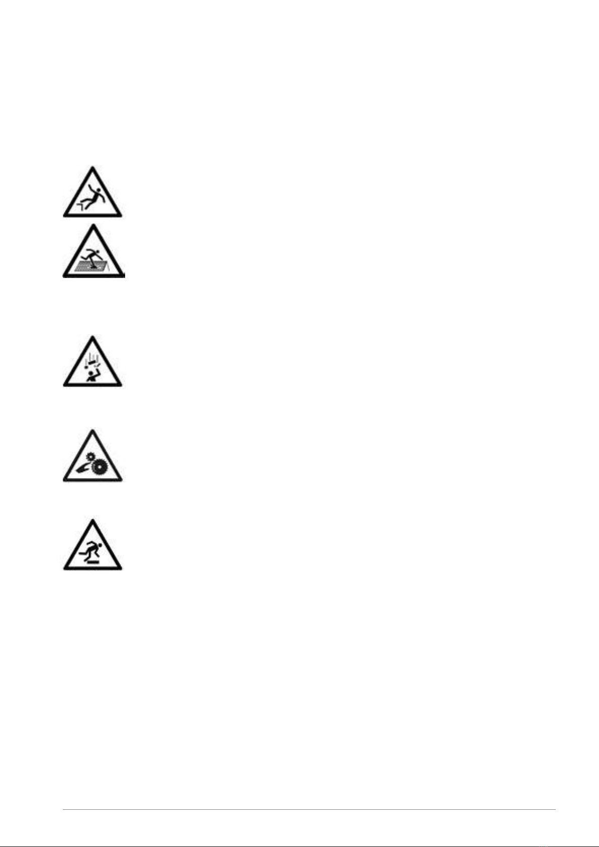
2 SAFETY
Take the necessary and required safety precautions, such as safety nets and lifelines when installing from the outside, safety
goggles, gloves, hard hat, etc.
Do not step on the glass.
Falling from height
• When using ladders to go on the roof:
- Ladder in good condition?
- Set up correctly at an angle of 75°?
- Secured below and on top against moving?
- Don’t take heavy material with you on the ladder (3-point contact rule)! If possible, use a crane to lift
the material.
• If you are going on the roof, make sure there is a walking surface that is wide enough and that
supports on the beams of the lower structure.
• When using an aerial work platform: always wear and secure your harness (mandatory)! Leaving the
cage is forbidden.
• Never walk backwards on a roof, always walk forwards.
• Make sure there’s enough light in the working zone.
Low-hanging obstacles and falling loads
• Forbidden to walk under or within a radius of 1m of a hanging or lifted load.
• Demarcate the danger zone below the zone where there is a risk of material falling down during the
installation of the veranda.
• It is prohibited to enter these danger zones during construction.
Crushing hazard
• All working tools are in good condition, provided with a valid CE label and all necessary safety
regulations. These cannot be removed.
• People who use these working tools are educated for this purpose. Protections are always present on all
working tools. They are in good condition and need to be set correctly.
Tripping/falling
• Safety is key and it begins with order and tidiness. Clean everything immediately, leave nothing lying
around.
• Trash needs to be sorted.
• Be cautious with electric cables (danger of tripping/falling). Never walk backwards!
• Make sure there’s enough light in the working zone.
01/03/2022 5/68
E_MH_Mounting_instructions_Skylux_Climax_Panorama
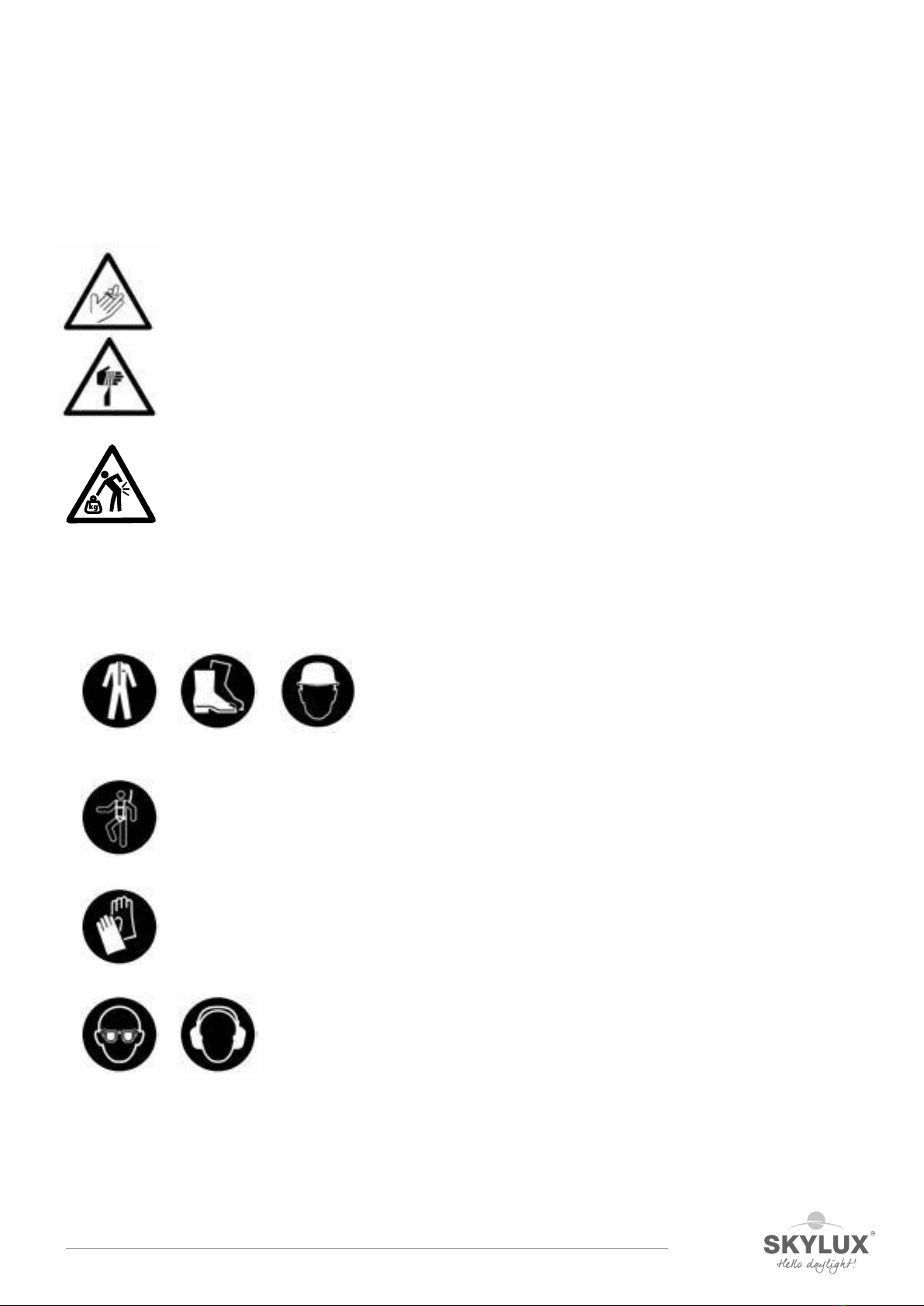
Sharp objects
• Make sure your fingers/hands are not pinched and watch out for cuts while handling veranda
parts.
• Be careful where you put your hands during the installation.
• Wearing cut-resistant gloves is mandatory.
Ergonomics
• Always lift loads correctly: bend your knees, move your feet instead of forcing your spine, lift
as close to your body as possible.
• Parts of more than 25kg must be lifted with at least 2 persons.
Personal protective equipment
• Work clothes, safety shoes and helmet are mandatory for everyone.
• Lifeline and harness are mandatory if the edge is not secured enough or if there are no safety nets below the
veranda roof. They are also necessary when using an aerial working platform.
• Use gloves when handling veranda parts.
• Safety glasses and hearing protection are mandatory when using saws / grinders.
Always perform a Last Minute Risc Analysis!
If in doubt: STOP! Do not take unnecessary risks. Ask your supervisor if needed.
E_MH_Mounting_instructions_Skylux_Climax_Panorama 01/03/2022
6/68
3 GUIDELINES
Safety during construction
Please read this manual carefully.
The installation must be carried out by people with sufficient technical knowledge and experience in the area of
conservatory installations (mechanical and electric). The installer must take the required safety measures into account
during the installation such as the use of scaffolding and personal protection equipment – safety shoes, helmet (i.e. hard
hat), gloves, safety goggles, etc. – to ensure the work is carried out in a safe environment. During installation, please make
sure that the necessary precautions have been taken to ensure the stability of the unfinished construction.
Stability
1) Statik
For roofs (attached or freestanding) that need a Statik, separate mounting instructions & corresponding parts are
provided.
2) Construction situation in general
The installer is responsible for the assessment of the appropriate fixing materials for the load and foundation on which
the structure is to be fixed. Please contact your fixing material supplier or specialised engineering consultants in case of
doubts. Skylux cannot be held responsible for the installation or the fixing materials used.
Seal installation
A distinction is made between push-in seals and slide seals.
The seal of a push-in seal is pushed into the profiles. The C2CX, C12, C8, CY10 and C31 seals are push-in seals.
The slide seals C1CX and C5 are slid into the profiles.
The seals C1CX and C2CX are equipped with an anti-stretch wire that prevents the seal from being stretched during
installation. This technology ensures that the seal cannot shrink after installation.
Avoid the use of silicone and detergent when installing the seals. Plastic sheets can be damaged by these products. Plastic
sheets can result in settlement noise due to temperature fluctuations. This will not affect the guarantee and will not be
accepted as a claim.
Terms, conditions and guarantee
The guarantee is void when the installation instructions provided below are not followed. Not following the instructions and/
or using other parts may have an adverse effect on the safety and life cycle of the product. Variations are not permitted
without written permission of the manufacturer. Our installation instructions manual and film are based on the latest level
of our knowledge and technics. We cannot be held responsible for possible incomplete information. Always check if our
product is suited for your application.
As the handling and installation of the product are done beyond our control, can Skylux not be held responsible for possible
damages.
The installer must take the specified span values in relation to the glazing and load (snow and wind) according to the
applicable standards into account.
The load graphs that you will find in this manual on page 7 are only indicative. Contact the manufacturer, architect or
engineering consultant for conservatory roofs outside the normal range.
Technical changes are reserved by the manufacturer without prior oral or written notification.
Skylux reserves the right to change this manual without prior notification. Changing the installation requirements or the
product will not mean a right to any compensation or exchange of parts.
The latest version of this manual can be consulted by visiting www.skylux.eu.
Climafast
The Climafast calculation application is offered by Skylux for free. You will receive information on how to log on and
download the Excel version of the application upon request. With Climafast, you can determine the price of your Climax
roof. An overview of profiles, lengths, parts, allowed loads, etc, is provided for each
project. The aim of this application is to inform the user.
Skylux reserves the right to change the Climafast application without
prior notification. The results of the application are indicative and
do not give right to any compensation. The latest version of the
calculation application can always be downloaded from
www.skylux.eu.
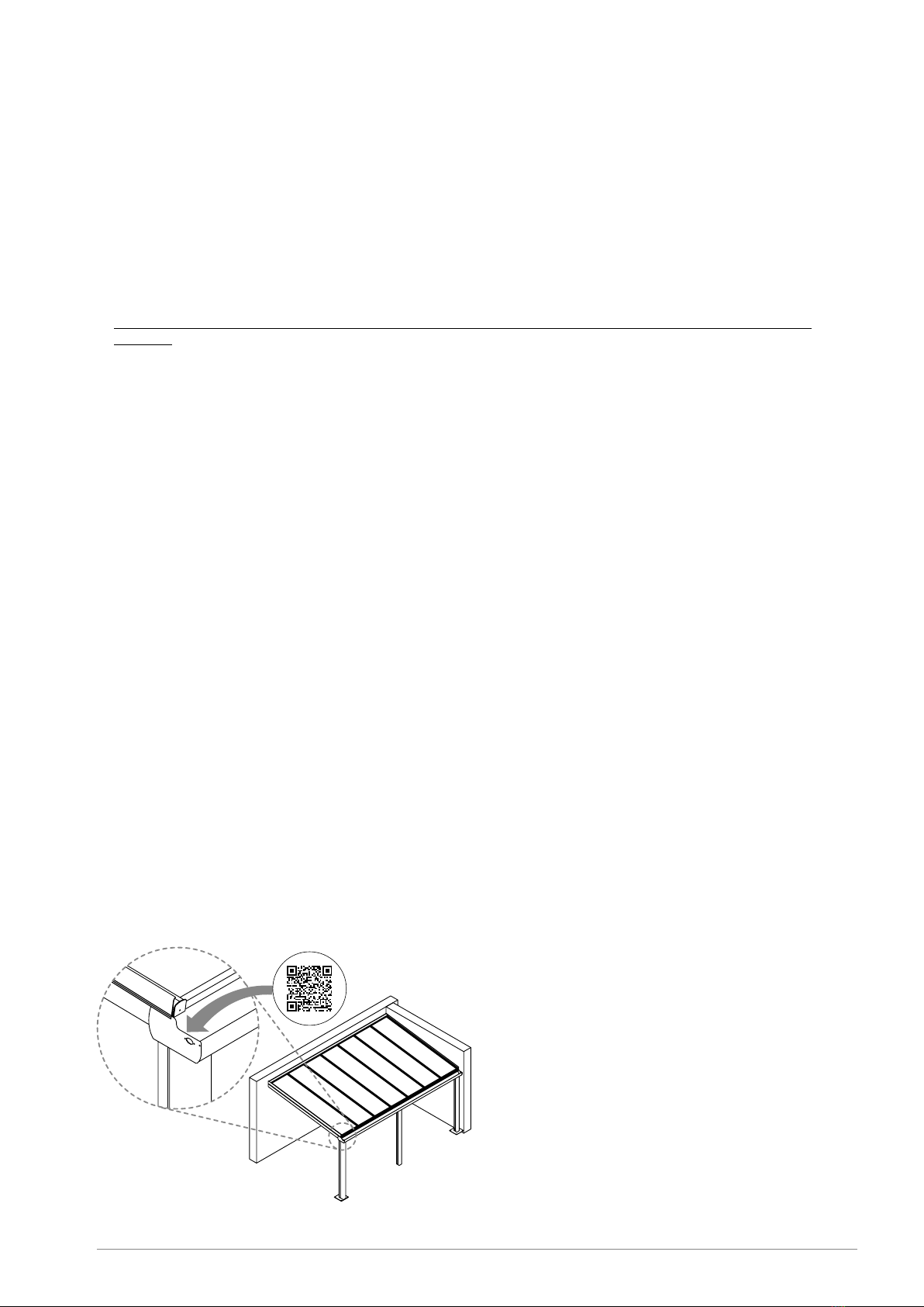
Questions or information about your canopy? Scan your
NFC code.
You will find this on the inside of the left gutter end plate
(see drawing). With this code, unique to your order, our
customer service can help you further.

01/03/2022 7/68
E_MH_Mounting_instructions_Skylux_Climax_Panorama
4 LOAD CAPACITY GRAPHS
4.1 General considerations
The following pages contain the load graphs for the Climax profile system. You can use these to determine the free span of
the gutter profiles and the supports in relation to the prescribed load.
A distinction is made between Climax roofs with plastic sheets (p. 8 & 9) and Climax roofs with single glazing (p. 10 & 11).
The maximum allowable bending is 1/200 (= 1cm per 200cm free span) with plastic sheets.
This includes the weight of the structure and the plastic sheets. Select the graph in relation to the prescribed snow and wind
load. This depends on the region and the orientation.
The maximum allowable bending is 1/300 (= 1cm per 300cm free span) with single glazing.
This includes the weight of the structure. In order to determine the total load, add the weight of the glazing to the
prescribed snow and wind load. To determine the weight of the glazing, calculate 2.5kg per m² and per mm thickness.
Example: single glazing with a thickness of 8mm weighs 8 x 2.5 = 20kg/m². After converting into N/ m² x factor 9.81, this
results in 20 x 9.81 = 196.20N/m². For double glazing, e.g. type 33.2/15/4, the cavatty is 15mm. The glass measures
6 + 4mm = 10mm. This weighs 10 x 2.5 = 25kg/m² or 245.25N/m². Suppose the prescribed snow and wind load is 500N/m²
and the glazing is 200N/m², the total load would be approximately 700N/m². In order to limit the weight of the glazing, the
axis distance between the support profiles (AX) is limited to a maximum of 750mm. The total width of the roof is divided into
equal parts.
The bending of 1/200 of 1/300 is achieved with a maximum load. For example, a gutter support of 5000mm with a maximum
bending of 1/300 will bend 16.6mm when loaded. Less if unloaded.
These graphs do not apply with regard to a continuous support or a structure under the gutter profiles installed by the
customer. The gutter profiles may put pressure on supporting window profiles when installed on top of each other.
A possible bending of the gutter profile above the sliding doors should therefore be taken into account.
When the selected gutter (support) cannot be installed where a certain span or load is concerned, select a gutter support
that can handle a larger span. You could also install an extra post to decrease the free span. “Span” refers to the distance
between the posts. The total width of the roof = the free span + the width of the posts.
The roof’s supporting posts should always be located at the corners of the roof. We do not recommend moving the post
supports inwards.
Any sunblind installed on the profiles are at your own risk and should be included in the calculation as an additional load.
In case of large spans or loads, the use of reinforcement profiles is recommended. These are slid into the aluminium profiles.
The galvanised reinforced profile V642 can be supplied. The other reinforcement profiles, such as IPE 120, are not provided.
They can be bought at any local hardware store. We recommend treating the reinforcement profiles with an anti-corrosion
product.
The selection of required fixing material is dependent on the foundation or the walls. Check whether the foundation and
the walls on which the structure is to be anchored have a sufficient load-bearing capacity. The installer is responsible for the
assessment of the appropriate fixing materials for the load and basis on which the structure is to be fixed. Please contact
your fixing material supplier or specialised engineering consultants in case of doubts. Skylux cannot be held liable for the
installation or the fixing material used.
We recommend removing any snow from the roof to prevent accumulation against the wall by the wind. When snow on a
higher roof can slide on to the Climax roof, measures must be taken to prevent this, for example, by using snow hooks and
snow beams.
You can use the Climafast calculation application to select the correct profiles and support in relation to the dimensions of
the Climax roof, the prescribed load and the glazing.
The latest version of this calculation application can always be downloaded from www.skylux.eu.
E_MH_Mounting_instructions_Skylux_Climax_Panorama 01/03/2022
8/68
350 N/m² & 1/200
2000
3000
4000
5000
6000
7000
8000
9000
2500
3000
3500
4000
4500
5000
D
P
GD1
GD1 +V642
GD2
GD2 + PL165
GDG
GDG + IPE120
500 N/m² & 1/200
2000
3000
4000
5000
6500
6000
7000
8000
9000
2500
3000
3500
4000
4500
5000
D
P
GD1
GD1 +V642
GD2
GD2 + PL165
GDG
GDG + IPE120
750 N/m² & 1/200
2000
3000
4000
5000
6000
7000
8000
2500
3000
3500
4000
4500
5000
D
P
GD1
GD1 +V642
GD2
GD2 + PL165
GDG
GDG + IPE120
1000 N/m² & 1/200
2000
3000
4000
5000
6000
7000
2500
3000
3500
4000
4500
5000
D
P
GD1
GD1 + V642
GD2
GD2 + PL165
GDG
GDG + IPE120
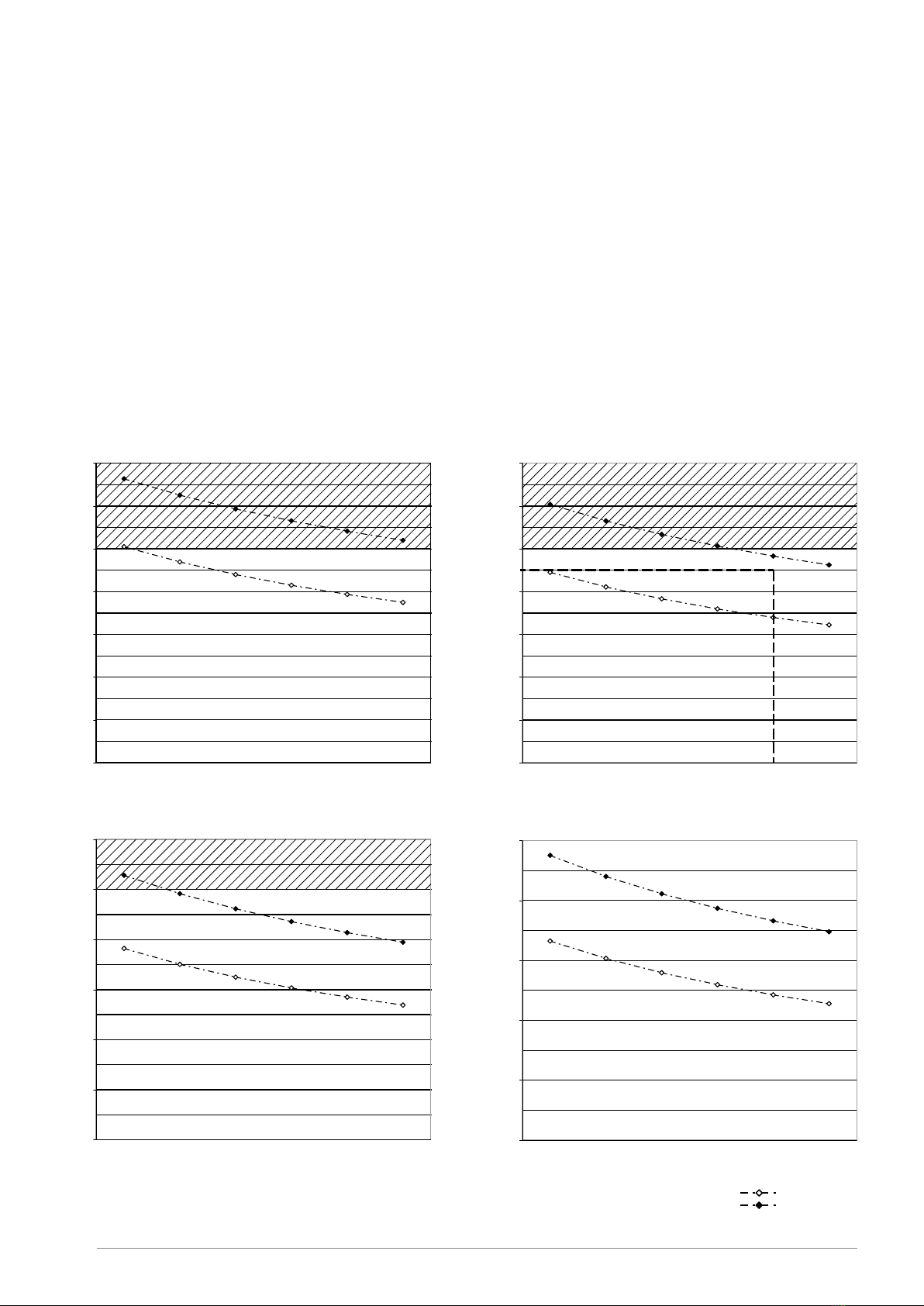
4.2 Load capacity graphs for roofs with plastic sheets
4.2.1 Gutter profiles
The graphs below can be used to determine the free span for each type of gutter (support). This is the distance (P) between
the supports (posts) in relation to the load and the depth (D) of the roof. The maximum bending is 1/200. The load is related
to the snow and wind load.
Practical example:
The roof has a width (B) of 6500m and a depth (D) of 4500mm. The prescribed load is 500N/m² (~50kg/m²). The roof is
provided with multi-layer plastic sheets.
Determine the point in the “500N/m² & 1/200” graph and select a gutter (support) that is above this point.
The graph now has two options:
Either you select gutter support GDG + IPE that will make allowances for a free span of 6780mm.
Or you select gutter support GDG that will make allowances for a free span of 5400mm. You then install an extra post in the
middle for support.
The span is the distance (P) between the posts. In this example, the width can be 7000mm where the free span (P) between
the posts = 7000 – 2 x 110 = 6780mm.
The bending in the middle with a load of 500N/m² is 1/200 or 6500/200 = 32.5mm. Less if unloaded.
The maximum gutter profile length we can supply is 7m.
350 N/m² & 1/200
2000
3000
4000
5000
6000
7000
8000
9000
2500
3000
3500
4000
4500
5000
D
P
GD1
GD1 +V642
GD2
GD2 + PL165
GDG
GDG + IPE120

01/03/2022 9/68
E_MH_Mounting_instructions_Skylux_Climax_Panorama
D1
D1+ V642
D1+ V644
D2
D2+ V1044
D3
D3+ PL105
2000
3000
4000
5000
6000
7000
8000
600700 800900 1000 1100 1200 1250
L
D
AX
350 N/m² & 1/200
D1
D1+ V642
D1+ V644
D2
D2+ V1044
D3
D3+ PL105
2000
3000
4000
5000
6000
7000
8000
600700 800900 1000 1100 1200 1250
LD
AX
500 N/m² & 1/200
D1
D1+ V642
D1+ V644
D2
D2+ V1044
D3
D3+ PL105
2000
3000
4000
5000
6000
7000
600700 800 900 1000 1100 1200 1250
L
D
AX
750 N/m² & 1/200
D1
D1+ V642
D1+ V644
D2
D2+ V1044
D3
D3+ PL105
1000
2000
3000
4000
5000
6000
600 700800 900100011001200 1250
LD
AX
1000 N/m² & 1/200
D1
D1+ V642
D1+ V644
D2
D2+ V1044
D3
D3+ PL105
2000
3000
4000
5000
6000
7000
8000
600700 800900 1000 1100 1200 1250
LD
AX
350 N/m² & 1/200
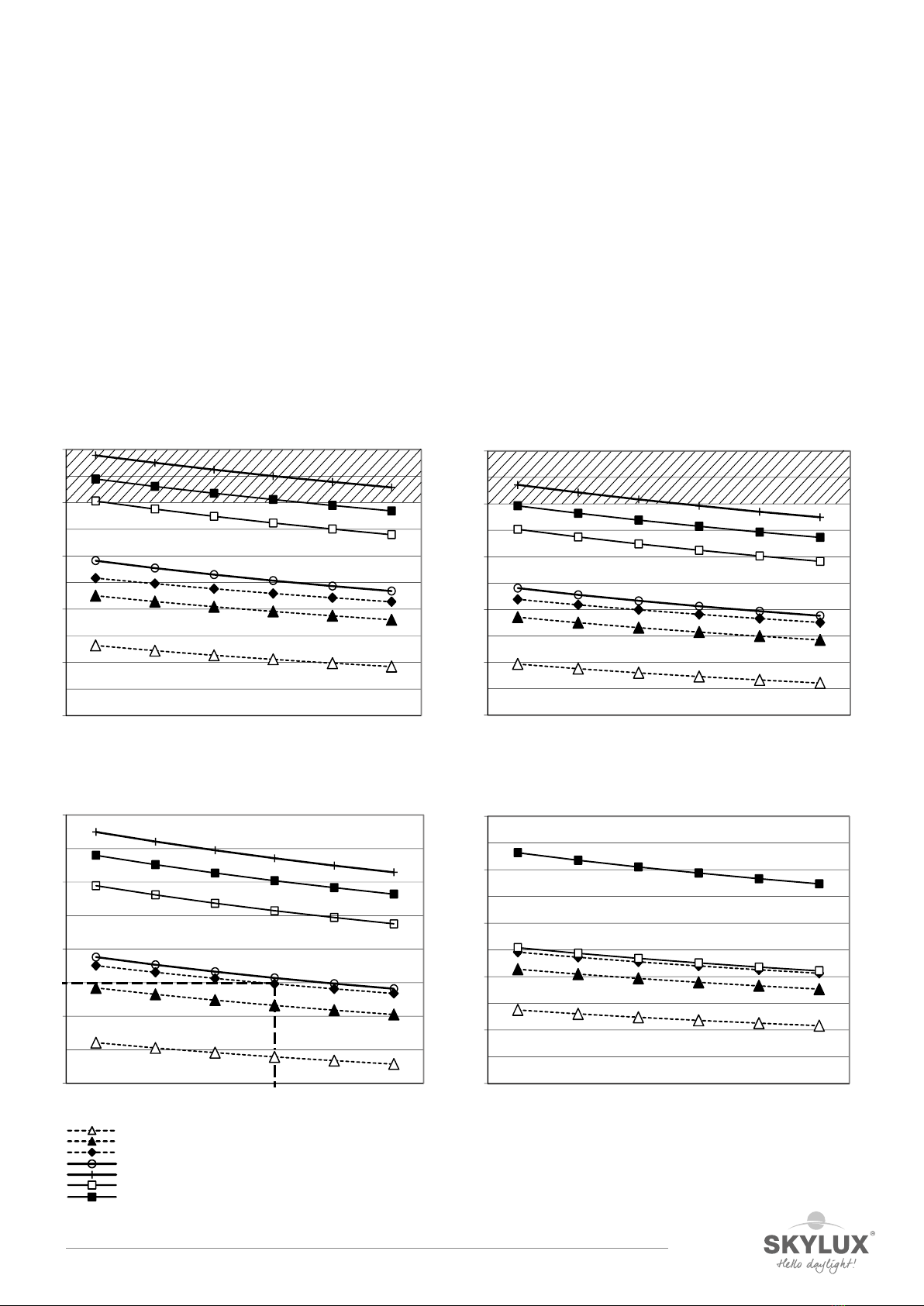
4.2.2 Rafter profiles
The graphs below can be used to determine the free span for each type of support (D1 or D2) with or without a
reinforcement profile. This is the maximum length of the support between the hinge profiles in relation to the load and the
depth (D) of the roof. The maximum bending is 1/200. In other words: a bending of 1cm for a free span of 200cm. The load is
related to the snow and wind load.
Practical example:
The axis distance (AX) between the support profiles is 1000mm (= with plastic sheets with a width of 980mm). The depth (D)
of the roof is 3500mm. The support length LDis > depth D for a roof pitch > 10°. Take this into account.
The prescribed load is 500N/m² (~ 50kg/m²). The roof is provided with multi-layer plastic sheets.
Determine the point in the “500N/m² & 1/200” graph and select a support that is above this point.
The graph now has two options:
You either select support D1 with reinforcement profile V642.
Or you select support D2 without reinforcement that can handle a slightly larger span.
The maximum bending (1/200) with a load is 17.5mm. Less if unloaded.
The maximum support profile length we can supply is 6m.
E_MH_Mounting_instructions_Skylux_Climax_Panorama 01/03/2022
10/68
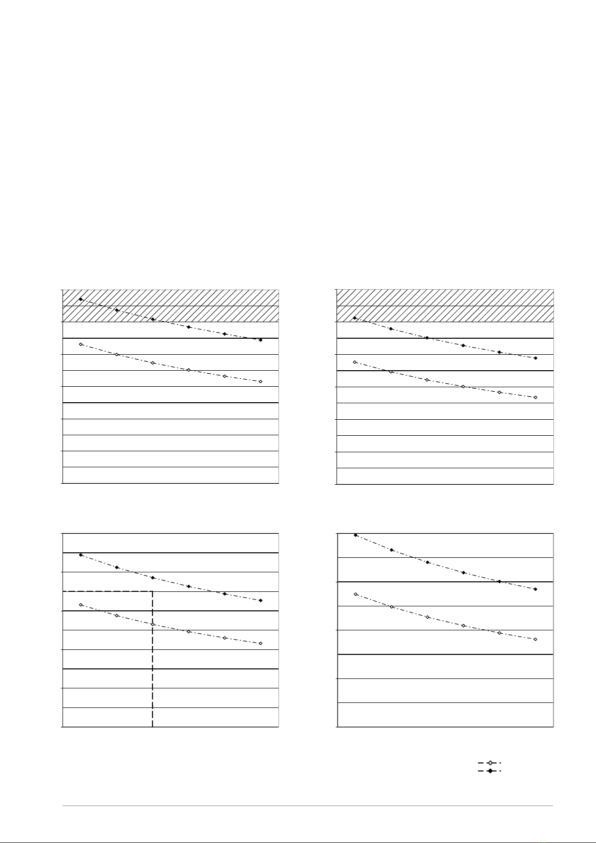
4.3 Load capacity graphs for roofs with glass
4.3.1 Gutter profiles
The graphs below can be used to determine the free span for each type of gutter (support). This is the distance (P) between
the supports (posts) in relation to the load and the depth (D) of the roof. The maximum bending for structures with glazing is
1/300. The load is the sum of the weight of the glazing and the snow and wind load applied to the roof.
Practical example:
The roof has a width (B) of 5500m and a depth (D) of 3500mm. The prescribed load is 500N/m² (~50kg/m²). The glazing
weighs 25kg/m² (approximately 250N/m²). The total load is 750N/m².
Determine the point in the “750N/m² & 1/300” graph and select a gutter (support) that is above this point.
The graph now has two options:
Either you select gutter GDG with reinforcement IPE 120 that will make allowances for a free span (P) of up to 5800mm.
Either you select gutter support GDG with a free span (P) of up to 4650mm between the posts. You then install an extra
post in the middle for support. With 2 posts, the width can be at most 5800 + 2 x 110 = 6020mm.
The maximum bending (1/300) in the middle with a load is 5500/300 = 18.3mm. Less if unloaded.
The maximum gutter profile length we can supply is 7m.
350 N/m² & 1/300
2000
3000
4000
5000
6000
7000
8000
2500
3000
3500
4000
4500
5000
D
P
GD1
GD1 +V642
GD2
GD2 + PL165
GDG
GDG + IPE120
500 N/m² & 1/300
2000
3000
4000
5000
6000
7000
8000
2500
3000
3500
4000
4500
5000
D
P
GD1
GD1 +V642
GD2
GD2 + PL165
GDG
GDG + IPE120
750 N/m² & 1/300
2000
3000
4000
50005000
5500
6000
7000
2500
3000
3500
4000
4500
5000
D
P
GD1
GD1 +V642
GD2
GD2 + PL165
GDG goot
GDG goot +IPE120
1000 N/m² & 1/300
2000
3000
4000
5000
6000
2500
3000
3500
4000
4500
5000
D
P
GD1 + V642
GD2
GD2 + PL165
GDG
GDG + IPE120
350 N/m² & 1/200
2000
3000
4000
5000
6000
7000
8000
9000
2500
3000
3500
4000
4500
5000
D
P
GD1
GD1 +V642
GD2
GD2 + PL165
GDG
GDG + IPE120
01/03/2022 11/68
E_MH_Mounting_instructions_Skylux_Climax_Panorama
D1
D1+ V642
D1+ V644
D2
D2+ V1044
D3
D3+ PL105
2000
3000
4000
5000
6000
7000
500550 600650 700750
LD
AX
350 N/m² & 1/300
2000
3000
4000
5000
6000
7000
500550 600650 700750
L
D
AX
500 N/m² & 1/300 D1
D1+ V642
D1+ V644
D2
D2+ V1044
D3
D3+ PL105
D1
D1+ V642
D1+ V644
D2
D2+ V1044
D3
D3+ PL105
2000
3000
4000
5000
6000
500550 600650 700750
L
D
AX
750 N/m² & 1/300
D1
D1+ V642
D1+ V644
D2
D2+ V1044
D3
D3+ PL105
1000
2000
3000
4000
5000
6000
500 550 600 650 700 750
L
D
AX
1000 N/m² & 1/300
D1
D1+ V642
D1+ V644
D2
D2+ V1044
D3
D3+ PL105
2000
3000
4000
5000
6000
7000
8000
600700 800900 1000 1100 1200 1250
LD
AX
350 N/m² & 1/200
4.3.2 Rafter profiles
The graphs below can be used to determine the free span for each type of support (D1 or D2) with or without a
reinforcement profile. This is the maximum length of the support between the hinge profiles in relation to the load and the
depth (D) of the roof.
The maximum bending is 1/300. In other words: a bending of 1cm for a free span of 300cm. The load is the sum of the weight
of the glazing and the snow and wind load applied to the roof.
Practical example:
The axis distance (AX) between the support profiles is 650mm. The depth (D) of the roof is 3500mm. The support length is
(LD) > depth D for a roof pitch > 10°. Take this into account. The prescribed load is 500N/m² (~50kg/m²). The glazing weighs
25kg/m² (approximately 250N/m²). The total load is 750N/m².
Determine the point in the “750N/m² & 1/300” graph below and select a support that is above this point.
The graph now has two options:
You either select support D1 with reinforcement profile V644.
Or you select support D2 without reinforcement.
The maximum bending (1/300) with a load is 3500/300 = 12mm. Less if unloaded.
The maximum support profile length we can supply is 6m.
E_MH_Mounting_instructions_Skylux_Climax_Panorama 01/03/2022
12/68
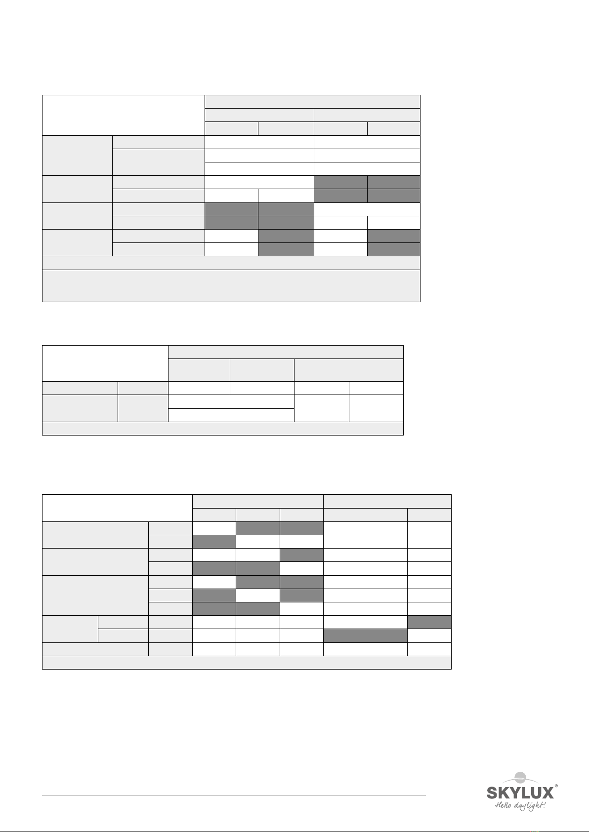
5 OVERVIEW INSTALLATION VARIABLES
5.1 Approach of mounting instructions
1) The tables below identify the relevant part combinations in function of your roof configuration.
The parts list can help you with this.
2) Afterwards, use the index at the beginning of this document to find the installation points with relevant
instructions.
5.2 Codes for the positioning of the elements
Codes for the positioning of the
profiles
Position
Side 1 Intermediate elements Side n
Posts Gutter posts P1.1 P1.2 ... P1.n
Roof overhang posts P1.1 P1.2 ... P1.n
Ridge posts P2.1 P2.2 ... P2.n
Horizontal
beam
Gutter beam G1 G2 ... Gn
Roof overhang beam O1 O2 ... On
Ridge beam H1 H2 ... Hn
Side beam W1 W2 ... Wn
Roof rafters R1 R2 ... Rn
5.3 Pitch
Pitch Degrees
Plastic / Pergotop / glass maximum 20°
Plastic guarantee minimum 10°
Plastic absolute minimum 5°
Glass advised minimum 5°
Glass absolute minimum 2°
5.4 Frame connections
Wall-supported pent roof:
Post type
P72 PGDX
P1.1 = P1.n P1.2 P1.1 = P1.n P1.2
Ground Standard PU72 + PV PU72 + (PV) PUX + PV PUX + (PV)
Statik GPV PU72 + (PV)
Gutter beam GDG - Standard PT72 + PU72
GDG - Statik KO + GPT
Overhang beam GDX – with/no Statik PUX + PT110
Side beam P72 - Statik PU72 PU72
Optional = (*)
To comply with the Statik:
- every Statik specific connection must be used.
- the roof dimensions are within the prescribed max. Statik dimensions.
01/03/2022 13/68
E_MH_Mounting_instructions_Skylux_Climax_Panorama
Freestanding pent roof:
Post type
P72 PGDX
P1.1 = P1.n P1.2 P2.1 = P1.n P2.2
Ground Standard VTPS01 on concrete VTPS on concrete
Statik VTPS01 in concrete VTPS in concrete
P72 in concrete PGDX in concrete
Gutter beam GDG - Standard KO + GPT
GDG - Statik KO + GPT KO + PU
Ridge beam GDX - Standard C110 + PT110
GDX - Statik C110 + PT110 PUX
Side beam P72 - with Statik posts PU72 PU72
P72 - no Statik posts C72 C72
Optional = (*)
To comply with the Statik:
- every Statik specific connection must be used.
- the roof dimensions are within the prescribed max. Statik dimensions..
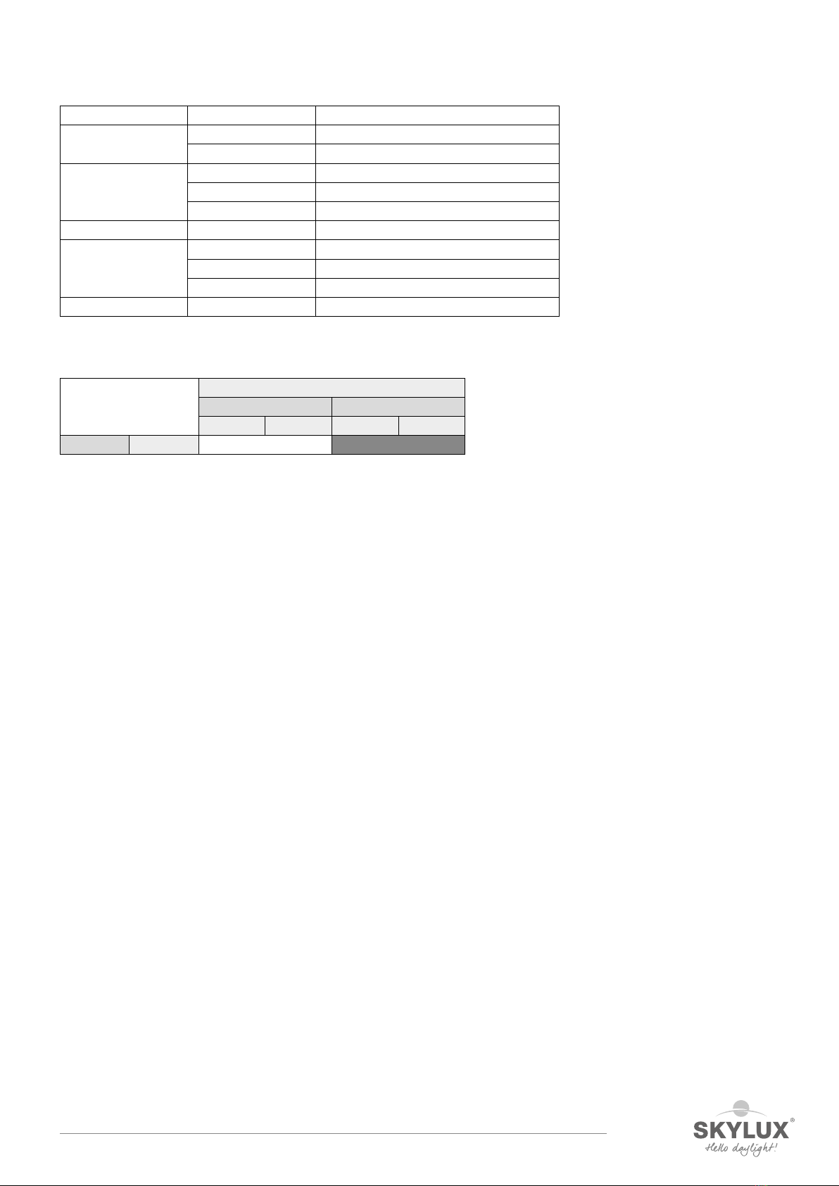
5.5 Horizontal beams
Extra elements
Extra elements
Steel
reinforcement
Beam
connector
Cover profile
Gutter beam GDG IPE120* GIP Without GDGK
Overhang beam &
ridge beam
GDX IPE 140* Without GDCX
V14105*
* Not provided
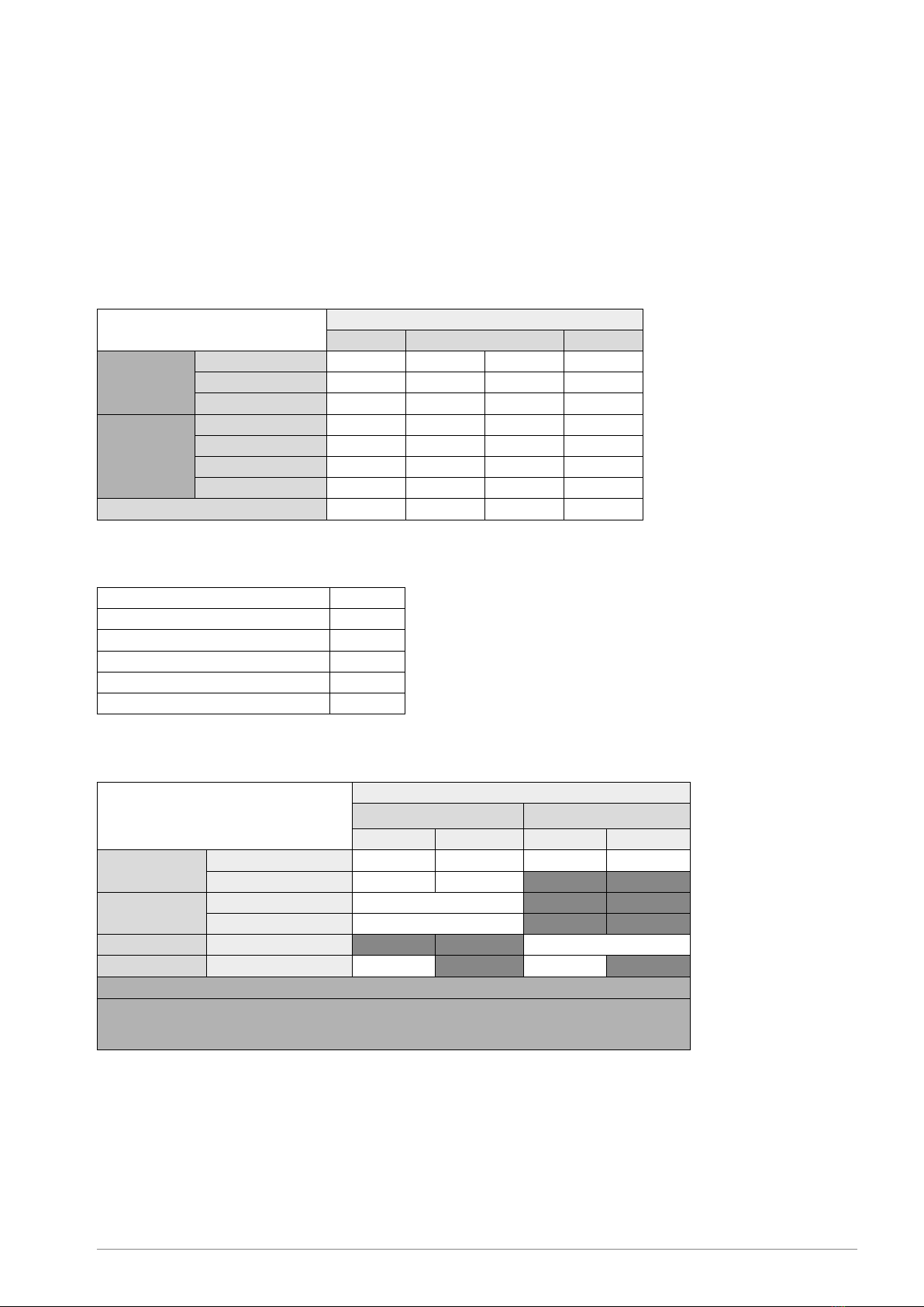
5.6 Roof package
5.6.1 Elements below glazing
Below glazing Rafter profile Glazing
D1 D2 D3 Plastic & Pergotop Glass
Hinge profile S1 + A1
S2 + A2
Connector K
KD3
Steel reinforcement V642
V1044*
PL105*
Thermal
break
Plastic TP
Glass TPG
LED profile VPLED
* Not provided

E_MH_Mounting_instructions_Skylux_Climax_Panorama 01/03/2022
14/68
5.6.2 Elements above glazing
Above
glazing
Screws Clips Seal
End-
plate
R1/Rn R2 R1/Rn R2 R1/Rn R1/Rn R2 R2 R1/Rn
Thickness CLSB + CLSL CLSB + CLST CL16 + L16P CL16 CLL CL32 + L16P CL32 C2CX C2CX + L16P
5 ++ / CY10 / °HL25 + / CY10 / °
S16.3
6 ++ / CY10 / °HL25 + / CY10 / °
7 ++ / CY10 / °HL25 + / CY10 / °
8 ++ / CY10 / ° HL25 ++ / CY10 /
9 ++ / CY10 / ° HL40
10 ++ / CY10 / ° HL40 + °
11 ++ / CY10 / ° HL40 + °
12 ++ / CY10 / ° HL40 + °
13 ++ / ° HL25 + ° +
14 ++ / ° HL25 + ° +
15 ++ / ° HL25 + ° +
16 ++ / ° HL25 ++ ++
17 ++ / ° HL40 + ° +
S32.3
18 ++ / ° HL40 + ° +
19 ++ / ° HL40 + ° +
20 ++ / ° HL40 +
21 ++ / ° HL40
22 ++ / ° HL40
23 ++ / ° HL40
24 ++ / ° HL40
25 ++ / ° HL40 ++ ++
26 ++ / ° HL40
27 ++ / ° HL40
28 ++ / ° HL40
29 ++ / ° HL40 + / Y32
30 ++ / ° HL40 + / Y32
31 ++ / ° HL40 + / Y32
32 ++ / °HL40 ++ ++ ++ / Y32
33 ++ / Y32 / * ° HL40 + / Y32
34 ++ / Y32/ * ° HL40 + / Y32
Legend
++ Ideal solution
+Good solution
Y32 Slide Y32 on TP
CY10 Use the CY10 seal on both sides of the CL/T16/32
* Always pre-dill, (Ø drill hole Y < Ø screw)
°Screw tightly
HL25 Hilo 25 screw
HL40 Hilo 40 screw
01/03/2022 15/68
E_MH_Mounting_instructions_Skylux_Climax_Panorama
5.7 Glazing edge profiles
Glazing Edge profile Description
Glass L432 Alu L finishing profile for glass (max. 38mm)
L632 Alu L finishing profile for glass (max. 60mm)
16mm sheet U16 Pre-drilled alu finishing profile 16mm
U16A Alu finishing profile 16mm
U16P Reinforced PVC finishing profile 16mm white
25mm sheet U25P
32mm sheet U32 Pre-drilled alu finishing profile 32mm
U32A Alu finishing profile 32mm
U32P Reinforced PVC finishing profile 32mm white
Glass connector GVT + GVB + (Y16P) Lower + upper profile + (thermal break)
5.8 Post covers
Post & post cover Post
P72 PGDX
P1.1 = P1.n P1.2 P2.1 = P2.n P2.2
Gutter GDG PCB72 + PC72

E_MH_Mounting_instructions_Skylux_Climax_Panorama 01/03/2022
16/68
6 MEASURING A WALL-SUPPORTED PENT ROOF
6.1 Overview element position code
6.2 Measuring
6.2.1 Determine the measurements
Determine height difference H.
Height difference H is the difference between the bottom side of wall profile MB and the bottom surface of the gutter
combination. The stop lip for the window is not included in the calculation.
Height h depends on the thickness of the glazing and the pitch angle where 1 or multiple thermal breaks Y16P are to be slid
in.
Determine the depth (see 6.2.1, image 1)
Measure from the wall to the inner side of the support post to determine roof depth D. The additional depth of the gutter is
219mm.
Determine the width B (see 6.2.1, image 1)
Width B of the Climax is the distance between the outer side of the side supports. If the Climax is installed between two
walls and a gutter with screwed-on gutter end pieces is used, you can deduct 5mm per side from width B. This is because the
screws for the gutter end piece require additional width and additional clearance is recommended.
These measurements can be used to calculate all other measurements using the Climafast calculation application that
is made available free of charge by Skylux. We strongly recommend the use of the calculation application. All possible
exceptions are taken into account. The correct cutting lengths are provided and only correct combinations are suggested.
The list of measurements for sizing is always provided with the materials.
P1.1
G1
P1.2
P1.n
R1
R2
Wn
H1
W1
Rn
R2 R2
Plaatdikte mm
Helling ° 5-35 36-45 5-20 21-35 36-40 41-45 5-30 31-34 41-45
Aantal Y16P 121234234
Hoogte h mm 156 172 156 172 188 204 172 188 204
Aantal Y16P in functie van plaatdikte en hellingshoek
0-16 17-25 26-34
Number of Y16P in function of sheet thickness and pitch angle
Sheet thickness mm
Pitch °
# Y16P
Height h mm

01/03/2022 17/68
E_MH_Mounting_instructions_Skylux_Climax_Panorama
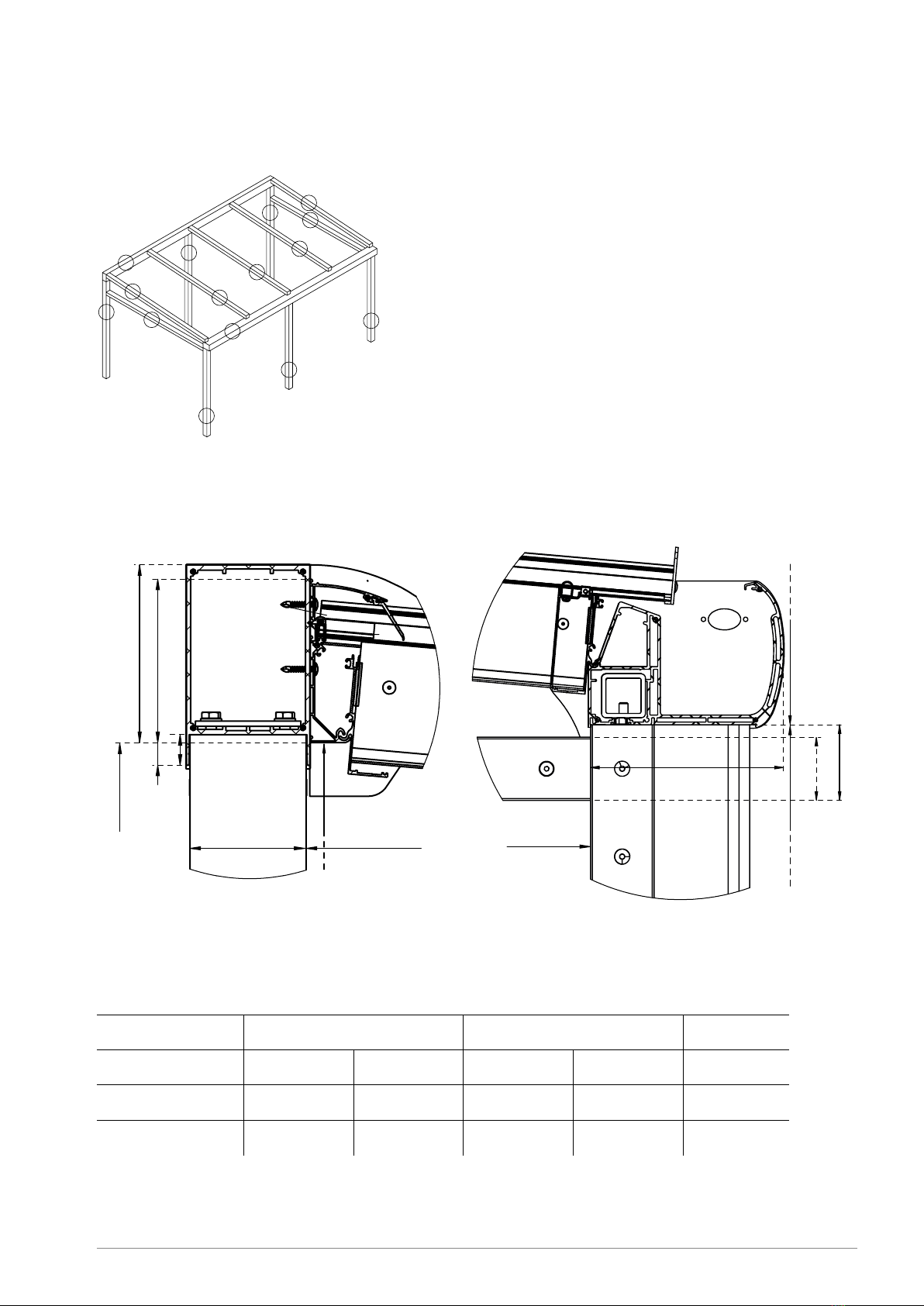
3
Installing the Climax post and the Climax PV base plate.
- Determine point O1.
- Determine O2. The distance O1- O2= conservatory width “B”.
- Draw a line with chalk using the 3/4/5 rule and determine
point P1. The distance O1- P1is the depth = D.
(Refer to item 3 below.)
- Repeat the same calculations for P2.
- Measure the distance (P1 - P2), which must be equal to
(O1- O2) as an additional check.
- The base plate can be slid through the slotted holes in order
to position the base plate properly.
- The U for the base plate can be moved 20mm either way to
allow proper adjustment.
The 3/4/5 rule.
- Determine the auxiliary point C1based on O1at a distance of
4 metres.
- Use a 3 metre string and a piece of chalk to draw a circle from
point O1.
- Use a 5 metre string to draw a circle from point C1
- The 2 circles intersect at C2.
- Line O1 - C2should be at a perfect right angle to your wall
(line C1-O1).
The difference in height H and depth D for the veranda.
HM= The height from the floor and the bottom side of the
wall bottom (MB) measured at the back of the veranda.
HN= The pitch of your veranda floor.
HG+ HN= Installation height from the bottom side of the
gutter. This is also the height for the windows or
the length of the posts.
H= HM- HG
h= Wall profile height
1
2
E_MH_Mounting_instructions_Skylux_Climax_Panorama 01/03/2022
18/68
7 MEASURING A FREESTANDING PENT ROOF
7.1 Overview element position code
7.2 Height & depth
7.2.1 Ridge & gutter beam
7.2.1.1 Height differences
Height h’ depends on the thickness of the glazing and the pitch angle where 1 or multiple thermal breaks Y16P are to be slid
in.
Number of Y16P in function of sheet thickness and pitch angle
Sheet thickness
0-16 17-25 26-34
Pitch ° 5-35 36-45 5-20 21-35 5-30
# Y16P 12122
Height h 156 172 156 172 172
P1.1
P1.2
G1
W1
R2
Wn
P2.1
R1
Rn
H1
P1.n
R2
R2
P2.2
P2.n
219 86
72
H
DH
G
168,5
h
29
21,5
H
HM
110 D
Y16P
01/03/2022 19/68
E_MH_Mounting_instructions_Skylux_Climax_Panorama
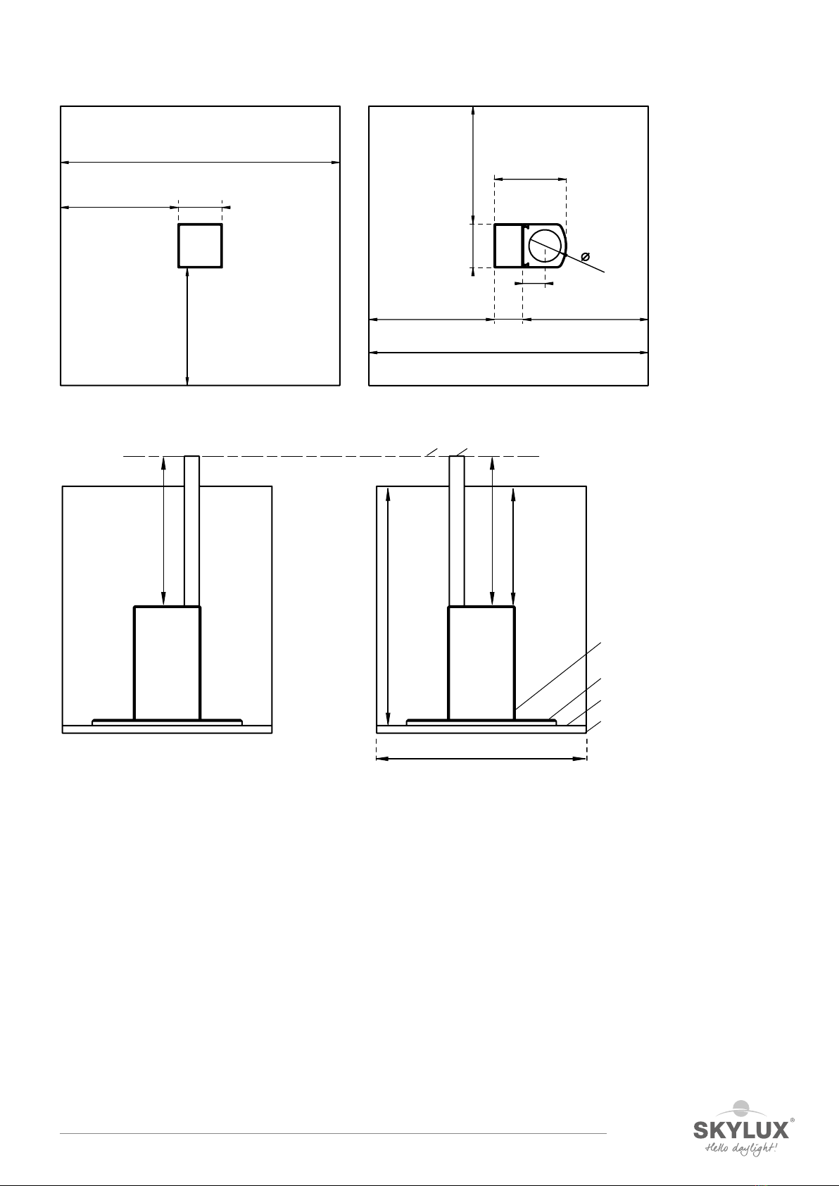
7.2.2 Cross-section of posts
7.3 Optional ground foundation
1. Soil
2. Sandbed
3. Tile
4. Concrete base
5. Level equal measuring posts
6. Level mason twine
700 min.
314 31472
295 181
55
80
110
700 min.
295
295
110
700 min.
800
min.
400
min.
= =
1
2
3
4
56

E_MH_Mounting_instructions_Skylux_Climax_Panorama 01/03/2022
20/68
8 MEASURING A WALL-SUPPORTED GABLE ROOF
8.1 Determine the measurements
The ridge of the gable roof must be attached to at least one wall.
Determine height difference H.
Height difference H is the difference between the bottom side of wall profile MB and the bottom surface of the gutter
combination. The stop lip for the window is not included in the calculation. Height H must be equal at the left and the right.
Height h’ depends on the thickness of the glazing and the pitch angle where 1 or multiple thermal breaks Y16P are to be slid
in
Determine the depth (see 8.1, image 1)
Measure the distance between the support posts P to determine roof depth D. The left depth DL may be different from the
right depth DR when the roof is asymmetrical. The maximum depth D is 6m. The additional depth of the gutter G equals
2x 219.
Determine the width B (see 8.1, image 1)
Width B of the Climax is the distance between the wall and the exterior of the side support. If the Climax gable roof
is installed between two walls and a gutter with screwed-on gutter end pieces is used, you can deduct 5mm per side
from width B. This is because the screws for the gutter end piece require additional width and additional clearance is
recommended.
These measurements can be used to calculate all other measurements using the Climafast calculation application that is
made available free of charge by Skylux. All possible exceptions are taken into account. The correct cutting lengths are
provided and only correct combinations are suggested. The list of measurements for sizing is always provided with the
materials.
Plaatdikte mm
Helling ° 5-35 36-45 5-20 21-35 36-40 41-45 5-30 31-40 41-45
Aantal Y16P 121234234
Hoogte h' mm 156 + 8 172 + 8 156 + 8 172 + 8 188 + 8 204 + 8 172 + 8 188 + 8 204 + 8
26-34
Aantal Y16P in functie van plaatdikte en hellingshoek
0-16 17-25
Number of Y16P in function of sheet thickness and pitch angle
Sheet thickness mm
Pitch °
# Y16P
Height h mm
Other manuals for Climax Panorama
1
Table of contents
Other SKYLUX Tent manuals


Popular Tent manuals by other brands


Skandika
Skandika Hammerfest 6 Protect Setup & maintenance

ZANE ARTS
ZANE ARTS ZEKU - M INNER TENT manual

Leofric Building Systems
Leofric Building Systems Broadway instruction manual

ShelterLogic
ShelterLogic MaxAP 23521 Assembly instructions

Skandika
Skandika Esbjerg Travel 4 Setup & maintenance

Gazelle
Gazelle T3 Assembly and use instructions

KING CANOPY
KING CANOPY Atlas AT1227S Assembly instructions

Hard Head
Hard Head 024169 operating instructions

CMi
CMi 476 678 operating instructions

Kinematic
Kinematic SidelinER PRO SetUp and Take Down Instructions

REDVERZ
REDVERZ SOLO EXPEDITION Setup instructions

Clam Customer
Clam Customer Quick-Set Escape 9281 Service information