SKYLUX Climalux 36179 User manual

CANOPY
Climalux®
Mounting instructions
EN
Art.N° 36179

E_MH_Mounting_instructions_Skylux_Climalux 01/11/2017
2/36
CONTENTS p. 2
OVERVIEW CLIMALUX PROFILES AND PARTS p. 3 - 4
GENERAL INSTALLATION TIPS p. 5 - 11
MEASURING YOUR CLIMALUX PITCHED ROOF p. 6 - 7
PREPARATION p. 8
GENERAL TIPS AND MAINTENANCE INSTRUCTIONS p. 9 - 10
PLAN OF CLIMALUX CONSERVATORY ROOF p. 11
SPECIFIC INSTALLATION TIPS FOR THE CLIMALUX SYSTEM p. 12 - 29
POSTS p. 13
GUTTER p. 14 - 16
GUTTER RAFTER FOR ROOF WITH OVERHANG p. 17 - 18
WALL PROFILE p. 19
RAFTERS AND SIDE RAFTERS p. 20 - 22
SPACERS p. 23
GLAZING p. 24
FINISH p. 25 - 29
ANNEX p. 30 - 35
LOAD GRAPHS p. 31 - 33
LOAD GRAPHS FOR RAFTERS p. 31
LOAD GRAPHS FOR GUTTER PROFILES p. 32 - 33
SPECIFIC INSTALLATION TIPS FOR LED LIGHTING p. 34
GLAZING THICKNESS TABLE p. 35
Table of contents

01/11/2017 3/36
E_MH_Mounting_instructions_Skylux_Climalux
Overview of Climalux profiles and parts
MX WALL PROFILE
GX GUTTER
GLX ORNAMENTAL PROFILE FOR GUTTER
GIX CONNECTING PIECE FOR GX
GDGL LED PROFILE FOR GDG
GR RAISED PROFILE FOR GUTTER GX
GDX GUTTER SUPPORT FOR OVERHANG
GDCX CLIP PROFILE FOR CROSS-BEAM GDX
DX RAFTER
L16P SIDE PROFILE 16 MM
CL16 CLIP ALU 16 MM
CLLX SIDE CLIP 16 MM
CLSB BASE SCREWABLE CLIP
FROM 7 UP TO 16 MM
CLST TOP SCREWABLE CLIP
CLSL TOP SCREWABLE SIDECLIP
PX POST 110/141 FOR GUTTER GX
PGDX POST 110/110 FOR CROSS-BEAM GDX
C1CX
COEXRUBBER FOR WALL TOP
WHITE/BLACK
COEXRUBBER FOR WALL TOP
GREY/BLACK
C2CX
COEXRUBBER WHITE/BLACK FOR
TP-TPG-TPGL
COEXRUBBER GREY/BLACK FOR
TP-TPG-TPGL
C3 RUBBER FOR SHEET SPACER GREY
CY10 RUBBER GREY FOR CL16 AND CLSB
C8 RUBBER GREY FOR CL16 AND CLSB
WALL
GUTTER
RAFTERS
POSTS
RUBBERS

E_MH_Mounting_instructions_Skylux_Climalux 01/11/2017
4/36
Overview of Climalux profiles and parts
AX SHEET SPACER
U16P REINFORCED PVC END PROFILE
16 MM WHITE
U16A ALU END PROFILE 16 MM
U16 PRE DRILLED ALU END PROFILE 16 MM
L432 L-OBTURATOR PROFILE
BT16 CLOSED SYNTHETIC TAPE FOR 10 AND
16 MM SHEETS WITH GARANTEE
BB16 PERFORATED SYNTHETIC TAPE FOR
16 MM SHEETS WITH GARANTEE
S16X STOP FOR DX
GSX END PIECE GUTTER FOR GX
GLSX END PIECE GUTTER FOR GX + GLX
GRSX END PIECE GUTTER FOR GX + GR
LOGO LOGO CLIMALUX FOR END PIECE
GUTTER
GDSX END PIECE FOR CROSS-BEAM GDX
MSX END PIECE WALL PROFILE FOR MX
909 CONNECTING PINS
LGDX FIXING PROFILE “L” FOR CROSS-BEAM
GDX
PV BASE-PLATE FOR POST PART 110/50
PU U TOP-BOTTOM FOR POST PX 110/141
PUX U TOP-BOTTOM FOR POST PGDX
110/110
BMR STAINL SCREW, NUT AND RING
SPRING M8
GC WATER OUTLET + SWIVEL
DIAM 80 MM GREY
UGS
WUGS
UNIVERSAL OUTLET +
OUTLET GUTTER SPOUT
ZSB/G
ZSC
STAINL. STEEL SCREW 5,5 x 32 MM
TX 25
STAINL. STEEL SCREW 5,5 x 32 MM
TX 25 WITH BUTYL SEALING
6,3 x 25 SELFDRILLING SCREW 6,3 x 25 mm
CLIMALUX
TX25
10
ACCESSORIES

01/11/2017 5/36
E_MH_Mounting_instructions_Skylux_Climalux
General installation tips
Please read this manual carefully.
The installation must be carried out by people with sucient technical knowledge and experience in the area of
conservatory installations. The installer must take the required safety measures into account during the installation
such as the use of scaolding and personal protection equipment - safety shoes, helmet (i.e. hard hat), gloves,
safety goggles, etc. - to ensure the work is carried out in a safe environment. During installation, please make sure
that the necessary precautions have been taken to ensure the stability of the unfinished construction.
Fixing material
The selection of required fixing material is to be made in function of the foundation or the walls. Check whether
the foundation and the walls on which the structure is to be anchored have a sucient load-bearing capacity. The
installer is responsible for the assessment of the appropriate fixing materials for the load and foundation on which
the structure is to be fixed. Please contact your fixing material supplier or specialised engineering consultants in
case of doubts. Skylux cannot be held responsible for the installation or the fixing materials used.
Seal installation
A distinction is made between push-in seals and slide seals.
The seal of a push-in seal is pushed into the profiles. The C2CX, C8 and CY10 seals are push-in seals.
The slide seals C1CX & C3 are slid into the profiles.
The seals C1CX and C2CX are equipped with an anti-stretch wire that prevents the seal from being stretched
during installation. This technology ensures that the seal cannot shrink after installation.
Avoid the use of silicone and detergent when installing the seals. Plastic sheets can be damaged by these products.
Plastic sheets can result in settlement noise due to temperature fluctuations. This will not aect the guarantee and
will not be accepted as a claim.
Terms, conditions and guarantee
The guarantee is void when the installation instructions provided below are not followed. Not following the
instructions and/or using other parts may have an adverse eect on the safety and life cycle of the product.
Variations are not permitted without written permission of the manufacturer. Our installation instructions manual
and film are based on the latest level of our knowledge and technics. We cannot be held responsible for possible
incomplete information. Always check if our product is suited for your application. As the manipulation and the
mounting of the product are done beyond our control, can Skylux not be held responsible for possible damages.
The installer must take the specified span values in relation to the glazing and load (snow and wind) according
to the applicable standards into account. The load graphs that you will find in this manual on page 31-33 are
only indicative. Contact the manufacturer, architect or engineering consultant for conservatory roofs outside
the normal range. The manufacturer reserves the right to change this manual without prior verbal or written
notification.
Skylux reserves the right to change this manual without prior notification. Changing the installation requirements
or the product will not mean a right to any compensation or exchange of parts.
The latest version of this manual can be consulted by visiting www.skylux.be.
Climafast
The Climafast calculation application is oered by Skylux for free and is at disposal of the professionals. You
will receive information on how to log on and download the Excel version of the application upon request. With
Climafast, you can determine the price of your Climalux roof. An overview of profiles, lengths, parts, allowed
loads, etc, is provided for each project. The aim of this application is to inform the user.
Skylux reserves the right to change the Climafast application without prior notification. The results of the
application are indicative and do not give right to any compensation. The latest version of the calculation
application can always be downloaded from www.skylux.be.

E_MH_Mounting_instructions_Skylux_Climalux 01/11/2017
6/36
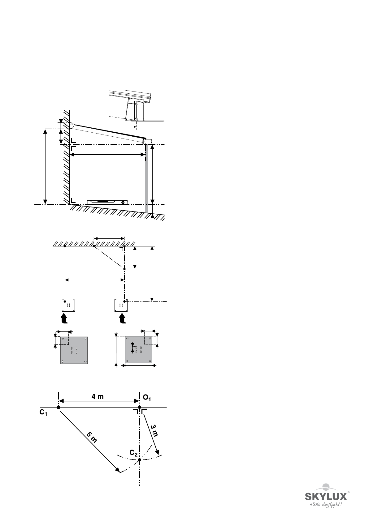
Measuring your Climalux pitched roof
Measurement
Determine the height dierence H.
The height dierence H is the dierence between the bottom side of the wall profile MX and the bottom surface
of the gutter combination. The stop lip for the window is not included in the calculation. The standard roof
inclination is 8°. Other inclinations are possible between min 5° and max 10°.
The height h is always 144 mm.
Determine the depth (fig 2, page 7)
Measure horizontally from the wall to the inner side of the support post to determine the roof depth D. The
additional depth of gutter GX is 160 mm, or of the gutter with ornamental frame GLX is 176 mm for a Climalux.
For a construction with eave, please consult page 22.
Determine the width B (fig 2, page 7)
The width B of the Climalux is the distance between the outer side of the side rafters. If the Climalux is installed
between two walls and a gutter with screwed-on gutter end-pieces is used, you can deduct 5 mm per side from
width B, as the screws for the gutter end piece require additional width and additional clearance is recommended.
These measurements can be used to calculate all other measurements using the Climafast calculation application,
which is available free of charge from Skylux. We strongly recommend the use of the calculation application.
All possible exceptions are taken into account. The correct cutting lengths are provided and only correct
combinations are suggested. The list of measurements for sizing is always provided with the materials.w
160
176
115
150
h = 144
H
D
B
H
D
01/11/2017 7/36
E_MH_Mounting_instructions_Skylux_Climalux
Measuring your Climalux pitched roof
Neem deze handleiding zorgvuldig door.
3
H
HMHG
HN
D
hD
1
O2
B
O1
P1
P2
C2
C1
3 m
4 m
5 m
D
20 mm
300 mm
300 mm
P1
100 mm
95 mm
95 mm
P2
100 mm
2Installing the Climalux post PX and PV base plate.
- Determine point O1.
- Determine O2. The distance O1 - O2= conservatory width “B”.
- Draw a line with chalk using the 3/4/5 rule and determine point
P1. The distance O1- P1is the depth = D
(Refer to item 3 below.)
- Repeat the same calculations for P2.
- Measure the distance (P1- P2), which must be equal to
(O1- O2) as an additional check.
- The base plate can be slid through the slotted holes in order
to position the base plate properly.
- The U for the base plate can be moved 20 mm either way to
allow proper adjustment.
The 3/4/5 rule.
- Determine the auxiliary point C1based on O1at a distance
of 4 metres
- Use a 3 metre string and a piece of chalk to draw a circle from
point O1.
- Use a 5 metre string to draw a circle from point C1.
- The 2 circles intersect at C2.
- Line O1- C2should be at a perfect right angle to your wall
(line C1-O1).
The dierence in height H and depth D for the veranda.
HM= The height from the floor and the bottom side of the
profile measured at the back of the veranda.
HN= The slope of your veranda floor.
HG+ HN= Installation height for the bottom side of gutter GX.
This is also the height for the windows or the length
of the posts.
H = HM- HG
h = 144 mm (wall profile height)
E_MH_Mounting_instructions_Skylux_Climalux 01/11/2017
8/36
Preparation
The Climalux roof can be delivered cut-to-size to reduce the installation time.
Walls
Check that the walls, against which the structure is to be installed, are:
- Suciently load-bearing to anchor the roof.
- Free of obstacles such as water drains, window sills ...
Install a lead slab to ensure a waterproof junction to the walls. Make a slot in the walls against which the
conservatory roof is to be installed. Install a lead slab or zinc flashing.
Height = first joint above Hm + h and max 60 mm above the wall profile.
LED lights (optional)
ClimaLED strips/spots: see p. 34. Please respect in time the specific requirements or modifications during
installation.
Floor
Ensure that the foundation can carry the load. Have an architect determine the required foundation. Implement
measures to remove rainwater from the roof.
Precautions
Protect the finished profiles against scratches and dents during installation.
01/11/2017 9/36
E_MH_Mounting_instructions_Skylux_Climalux
uNearly all silicone products affect
the polymethyl methacrylate or poly-
carbonate sheets. Purchase silicone
types that are safe for polymethyl
methacrylate or polycarbonate pro-
ducts (guarantee certificate).
uThe fumes from this putty may
never evaporate in the slots of the
sheet. The ventilation openings as well
as the sides of the end profiles may
not be closed off. The silicone should
always be allowed to release fumes
freely.
uSome seals contain softening agents
(as used in certain types of rubber,
PVC, polyurethane, etc.) that may
cause small cracks. Use only approved
seals.
uDo not use black or dark-coloured
seals to prevent heat accumulation.
uA lead slab may be placed on the
seals but may not rest against the
sheets.
uSome paints, varnishes and wood
protectors affect the polymethyl
methacrylate or polycarbonate sheets.
Never use lubricants to put the seals
into the profiles.
uNever spray insecticide directly on
to the sheets. Synthetic sheets can be
damaged by these products.
2. SILICONE, SEALS AND
WOOD PROTECTORS
uObserve the safety instructions
that apply to work on roofs.
Polycarbonate sheets: Very
IMPORTANT! The side which is
protected against UV radiation
must always be installed facing
the exterior or the sky. The “sun
side” is indicated on the protec-
tion film.
uThe plastic tape or the provisional
aluminium tape will only ensure the
sheets are free from dust while being
shipped. These should be removed!
Adjusted aluminium tape or end pro-
files must be used.
uThe load-bearing structure must
be strong and stable. (See the regu-
lations that apply to the timber and
metal construction industry.) Cross
supports may be required depending
on the type of sheet used. Only spe-
cific maximum lengths may be used
without a cross support for each
type of sheet taking into account
the loads of 500 N/m2or 750 N/
m2, respectively (see the technical
plastic sheets information sheet).
uPergotop/Pergotop-soft sandwich
panels are only adapted in combina-
tion with Skylux screwable clips.
uHeat accumulation: the top side
of the load-bearing structure that is
turned towards the sheets must be
WHITE reflective.
4. INSTALLATION
Synthetic sheets can expand or shrink
when there are temperature fluctua-
tions. The following tips should be
taken into account:
uEnsure there is 5 mm clearance
lengthwise for each sheet meter and
ensure there is 10 mm clearance
(5 mm on each side) widthwise, for
example, a 3000 mm sheet must
have a clearance lengthwise of 1.5 cm.
uNever block the sheet lengthwise
or widthwise. Always ensure sufficient
clearance.
uNever stick the sheet using silicone
(even when it does not damage syn-
thetic materials). It would prevent the
expansion and shrinkage of the sheets.
uThe sheet is blocked at the bot-
tom end to prevent it from sliding. The
clearance must, therefore, be pro-
vided at the top.
1. CLEARANCE
5 mm 5 mm
uApply white dispersion paint (diluted
in water or paint without solvents) or use
preferably aluminium tape. Attention:
Let the paint dry after painting the
load-bearing structure! Continue with
the installation of the sheets after the
paint has dried. The synthetic sheets may
NEVER be installed directly on to tim-
ber structures.
uDo not place roof tiles directly on
the sheets! Leave a space of at least
10 mm between the sheets and the
roof covering.
uUse a special weather stripping (seal
C6) for sealing the opening between
the plate and the gutter beam. Do not
seal using sealant or fill with PU foam.
uWe formally recommend not add-
ing a ceiling under the acrylic sheets
(PMMA). Any used sun blinds or
other finish under the sheets should
be at least 120 mm from the roofing
sheet. These may not have insulation
properties and should have a reflect-
ing colour. The polycarbonate sheets
(PC) do not require any specific pre-
cautions.
u
WIDTH DISTRIBUTION
OF THE SHEETS:
RECOMMENDED:
standard
sheet width with an adapter for the 2
outer sheets. This is especially impor-
tant for the S5P heat-stop sheet.
NOT RECOMMENDED:
in equal sections with sized sheet
widths. Take the standard sheet width
into account. We formally advise
against sizing multiple-layer sheets.
The closed off sides are
one of the factors that
determine the sheet
strength!
uFollow the installation instructions
provided by the glass manufacturer
when including the installation of
glass!
5. GLASS
uClean the sheets annually using
lukewarm rainwater. Dissolve a little
household soap (neutral) in the water
if required (no detergent!!). Never use
solvents or abrasive products.
uDo not rub dry (may cause
scratches).
uSimply rinse.
3. MAINTENANCE
Space for expansion
uClean the surfaces/profiles min.
1 a year with cold water and a mild
soap. Rinse well with plenty of
water.
Never use solvents or abrasives!
A good cleaning is necessary to
avoid the profiles from growing dull
and dirty by the UV light!
General tips and maintenance instructons
The qualitative and technological level of the multiple layer plastic sheet is high. We provide a few important tips for problem-free
installation. Please pay special attention to the following: Space for expansion/silicone and wooden protection/seals.

E_MH_Mounting_instructions_Skylux_Climalux 01/11/2017
10/36
SILICON
E
6. DRAINAGE AND CONDENSATION
uInstall the sheets with inclination or
vertically, never horizontally (unless
interior use).
uMinimum inclination: 10° (18 cm
per meter) or more.
uThe direction of the sheet canals
must always go along with the roof
inclination.
7. SHEET DIRECTION
°°
° °
uType of saw blade:
1. hard metal (for ca 50 m/s)
uMake sure that the bottom NEVER
stands in water (moss and algae).
uCondensation in the canals is not
100% inevitable (physical phenome-
non).
Acrylic and polycarbonate are very
less gas- and dampproof. The charac-
teristics of the material and the gua-
rantee are not diminished because of
this. An appropriate sealing is recom-
mended.
uAlways use a grease pencil to make
notes on the protection film (felt pen
is difficult to remove).
uTo ensure a fest clamping during the
sawing, you should always make sure
that a raised rib is as near as possible
by a sawed edge.
9. SAWING AND DRILLING
uWhen sawing, use a hard metal saw
(widea) with high rotation speed. Saw
slowly and by preference with one
move. Use new or sharpened saw bla-
des. Make sure the sides are always
smooth.
ATTENTION: The basis on which the
sheets are sawn, must be stable and
vibration-free. The sheets must not
move during sawing. The saw blade
must slightly reach out of the sheet.
uRemove all dust and sawing rests
from the canals with pure compressed
air or a powerful vacuum cleaner.
uOnly remove the protection film
after installation to avoid scratches.
uDrilling is strongly advised against.
However, if unavoidable, provide with
grooves (shrinking and dilatation).
°°
°°
°°
2. HSS (not more than 40 m/s)
uAvoid direct sunlight on piled
sheets.
uIf you pile the sheets outside, cover
the sheets with white polyethyl foil.
Always keep the synthetic friendly
tape as sealing on the front sides of
the sheets.
uThe sheets must not be piled direct-
ly on the ground. Use appropriate pal-
let boards.
10. PILING
uNever walk or kneel directly on the
sheets. Always use solid timber boards
underneath. Make sure these boards
are supported by the timber construc-
tion.
uMulti-walled synthetic sheets with
thin walls and a high insulating struc-
ture in the sheet, are sensitive to foot,
knee and other impressions at the
surface. Please take enough precau-
tions during transport and installa-
tion. Impressions in the sheet are not
covered by the guarantee.
12. REMEMBER
uAs we already mentioned several
times, synthetic sheets shrink and
dilate under the influence of tempe-
rature fluctuations. When they move
with regard to the roof construction,
there can be some creak noises. There
is no danger for the sheets if they
have been installed according to the
installation instructions.
u
Screwed clipses cause more creak
noises with synthetic sheets
.
u
If you would like to avoid crack
noises, we advise you to always use
the TP and TPH profiles. The TP can
expand and shrink with the synthetic
sheets or alu sandwich sheets.
14. DILATATION NOISES
Dust and damp may not enter into the
cell structure:
uA combination of BT 16/25/32
at the top and BB 16/25/32 with
U16/25/32P at the bottom, stops
dust of
> 45μm from entering the cell
structure.
uThe underside is provided with a
perforated aluminium filter tape.
To protect the tape, use the U16P/
U25P/U32P or a U profile with per-
forations of Ø 3.5 mm, installed every
20 cm.
uSeal the profile with synthetic
friendly silicone to prevent water infil-
tration maximally.
u
Wet the edge of sheets with no-
drop layer and dry it afterwards before
taping the sheet.
uIf you install sun protection, you
must do this on the upper side of the
sheets: e.g. on the outside.
Attention:
Do not put the sun protection directly
on the sheet!
You can also buy sunproof sheets
(PC: Primalite Clear, Reflex Pearl,
Relax - PMMA: S5P Heatstop) or
install a Skylux conservatory dome.
11. SUN PROTECTION
uThe multi-walled synthetic sheets
resist normal snow load. You can find
the maximum snow load on the tech-
nical files per sheet type and size. In
case of heavy snow fall, we recom-
mend to regularly clear the snow.
The conservatory roof must also be
protected against snow falling from a
higher situated roof.
13. SNOW AND SNOW PILE
uOnly use sheets with identic pro-
duction number per project to avoid
colour differences.
15. FURTHER INSTRUCTIONS
uMulti-walled synthetic sheets may
reflect the sunlight to the inside or
the outside in case of direct sunlight
(following the orientation or the
inclination). This is a normal situation
which does not affect the sheet gua-
rantee.
8. REFLECTION

01/11/2017 11/36
E_MH_Mounting_instructions_Skylux_Climalux
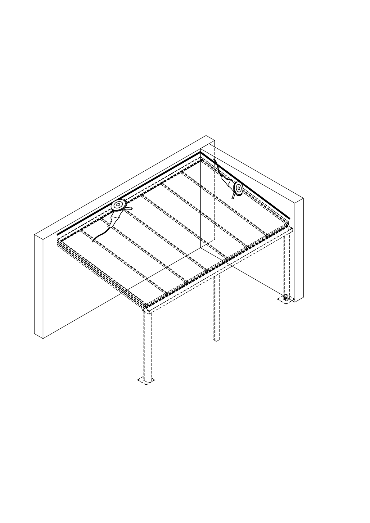
Overview drawing of the conservatory roof
A10 - A11: posts, page 13, 29
A20 - A23: gutters, page 14-18, 29
A30 - A33: wall profiles, page 19, 29
A40 - A42: rafters, side rafters, page 20-28
A10
A11
A20
A21
A22
A23
A40
A41
A42
A30
A31
A32
A33

E_MH_Mounting_instructions_Skylux_Climalux 01/11/2017
12/36
Climalux®
Installation tips
01/11/2017 13/36
E_MH_Mounting_instructions_Skylux_Climalux
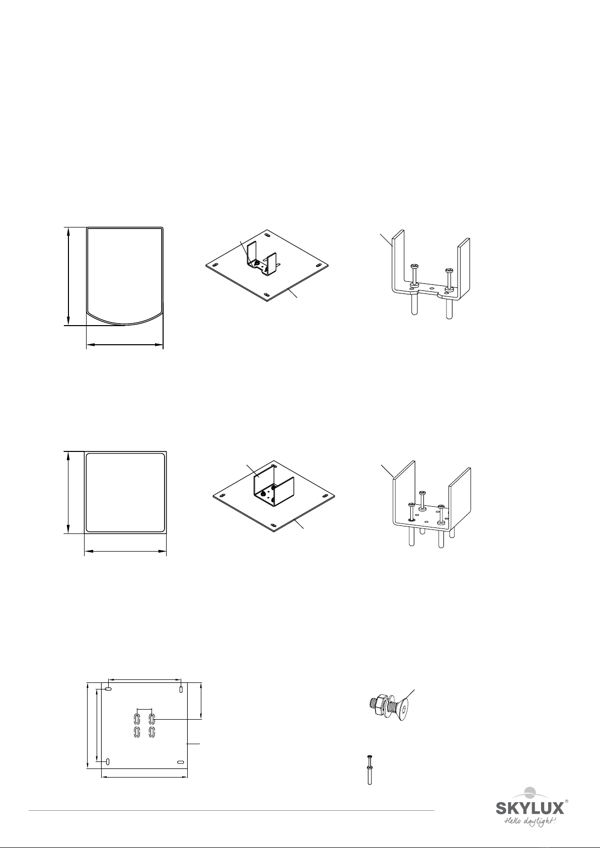
Climalux®
Installation tips
Posts
Determine the length of the posts (HN+ HG) in function of the slope and the position of the wall profile (HM).
Post for gutter GX accessories for corner post accessories for middle post
Base plate PV (optional) and U-shaped bracket U-bracket
Post PX 110/141
Post for gutter rafter GDX
(for roof with overhang)
Post PGDX 110/110 for gutter rafter GDX
Bolt the U-bracket to the PV base plates (fig A) using the BMR screw set (fig B) for the corner posts. Determine
the position of the PV base plates as indicated on page 7 and anchor these on a solid foundation in concrete using
the suitable fixing accessories (not supplied). Position the U-bracket correctly on the base plate and fix it. The
U-bracket for the middle posts can be installed without a base plate directly on a solid basis. Position the posts
over the brackets. Position these perpendicularly (level) and shore these temporarily to ensure they do not fall
over. The top part of all posts must be completely aligned and level.
Fig. A Fig. B
110
141
PU
PV
(optional)
PU
110
110
PUX
PV
PUX
52
300
300
127,5
253,5
253,5
PV
BMR
not supplied

E_MH_Mounting_instructions_Skylux_Climalux 01/11/2017
14/36
Gutter
Multiple gutter combinations are possible.
Use the load graphs on page 31-33 or calculate using the Climafast calculation application:
gutter combination (with reinforcement profile
GX (+ V822)
GX + GLX (+ V822)
GX + GR (+ V822)
Make sure there is a play of 10 mm if the gutter combination is to be installed between two walls. The 5 mm
clearance on each side is required for the installation of the slide ends.
Pre-drilling is required to install the U-brackets if the gutter (rafter) is reinforced with a steel profile. The use of
strong self-drilling screws is recommended.
* The reinforcement profile V822 is not supplied. It can be bought at any local hardware store.
We recommend treating the reinforcement profiles with an anti-corrosion product.
160
115
90,5
211,58
V822
GX
150
176 51,58
90,5
V822
GX
GLX
90,5
160 51,58
211,7
61,5
GX
GR
V822

01/11/2017 15/36
E_MH_Mounting_instructions_Skylux_Climalux
Gutter GX
Assemble the gutter components to prepare for the installation of the gutter
Cut out the opening for the water outlet.
Use a Ø 80 mm circular drill (not supplied).
Slide in the reinforcement profile V822 (optional).
Installation of the U-bracket PU
Use the post caliber for the correct positioning.
* The reinforcement profile V822 is not supplied. It can be bought at any local hardware store.
We recommend treating the reinforcement profiles with an anti-corrosion product.
Ø 80
55
86
GX
GX
V822
4
2
2
4
55
86
PU
ZSB (3x)
E_MH_Mounting_instructions_Skylux_Climalux 01/11/2017
16/36
Gutter
Multiple gutter elements can be connected to each other for gutter lengths > 7 m.
A gutter support must be installed at every gutter connection point.
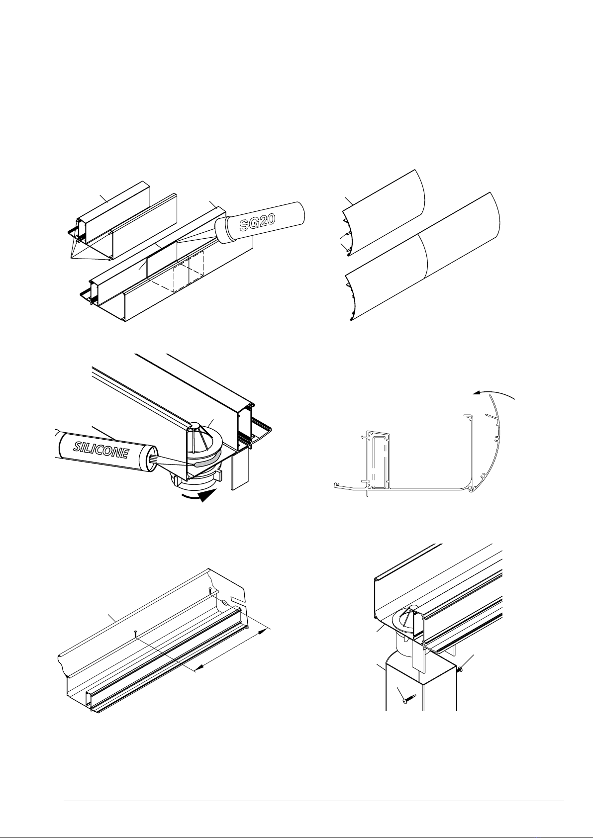
The gutter profiles can be linked using connection pins 909 and the connector profile GIX. Use silicone SG20 as
sealant.
GLX + 909 (2x)GX + GIX + 909 (4x)
GX GX
909
GIX
GLX
909
A raised profile GR can be installed on the GX gutter. Position
the side gutter slide ends first and subsequently fasten the
GR profile on to the gutter every 500 mm.
500
GR
Install the water outlet in the gutter opening and seal using
silicone.
GC
GX
The ornamental frame GLX is clipsed by a turning movement
on to the gutter. Start at one of the ends.
click
Place the pre-assembled gutter on the posts and fasten the
construction using lacquered screws ZSG. The gutter slide
ends must be pre-installed now if the gutter is installed
between two walls (see page 29).
ZSG
ZSG
GX
PX
01/11/2017 17/36
E_MH_Mounting_instructions_Skylux_Climalux
Gutter rafter for roof with overhang
Components
gutter combination (with reinforced profile)
GDX + GDCX (+ V14105)
Preparation
* The reinforcement profile V14105 is not supplied. It can be bought at any local hardware store.
We recommend treating the reinforcement profiles with an anti-corrosion product.
117
190
100
140
GDX
GDCX
V14105
Installation of the U-bracket PUX.Slide in the reinforcement profile V14105 (optional). Fixing
the reinforcement profile V14105 on to the GDX (top and
bottom) has a favourable influence on the solidness.
V14105
GDX
3,8
7,7
PUX
ZSB (4x)

E_MH_Mounting_instructions_Skylux_Climalux 01/11/2017
18/36
Gutter rafter for roof with overhang
Installation
The construction of the gutter rafter supports the (side)rafters DX (page 22).
Fix the slide ends GDSX with the ZSG
screws.
Fix the gutter rafter on the posts and fasten the
construction with the lacquered screws ZSG.
Multiple gutter elements can be connected to each other
for gutter lengths > 7 m. A gutter support must be installed
at every gutter connection point. The gutter profiles can
be linked using the reinforced profile V14105 and the
connection pins 909. Fasten the gutter rafters GDX on top
and bottom on to the reinforcement profile V14105.
Cut the finishing clips to length and clips it
at the bottom side of the gutter rafter GDX.
PUX GDX
PGDX
ZSG
ZSG
ZSG (4x)
GDSX
GDX
PGDX
909
GDX
GDX
909
GDCX
GDX
CLICK

01/11/2017 19/36
E_MH_Mounting_instructions_Skylux_Climalux
Wall profile
Components
Preparation
Install a lead slab to ensure a waterproof junction to the walls. Make a slot in the walls against which the
conservatory roof is to be installed (page 8). Install a lead slab or zinc flashing.
Drill a hole in the wall profile MX at 250 mm from the ends and subsequently every 500 mm at the top indication
line with a diameter in function of the chosen fixing material. Drill also a hole every 500 mm in the bottom
indication line and start at 30 mm from the edge.
Important: Slight the rubber C1CX in the profile MX before mounting.
Installation
Fix the wall profile using the adapted anchoring. The holes in the bottom wall profile correspond to the height HM
+ 19 mm and HM + 109 mm on the wall.
Finish the top side of the wall profile with silicone and with a lead slab or zinc flashing built-in in the wall.
143,6
30
39,5
19 90
98°
C1CX
MX
500 250
30
500
500
500
500

E_MH_Mounting_instructions_Skylux_Climalux 01/11/2017
20/36
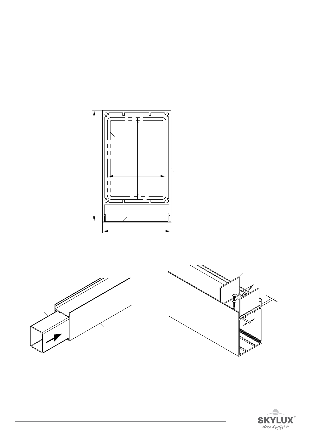
Rafters and side rafters
The rafters are pre-cut at the wall and gutter side. The slot at the wall side corresponds tot the rib of the wall
profile. Check the rafter lengths in function of the glazing + snow and wind load (Use the load graphs on page 31
or calculate using the Climafast calculation application, at disposal for free for professionals).
Components
Rafter
DX + C3 (or CY10)
The rafters DX are pre-cut-to-size.
Preparation
Fix the support seals on both sides of the rafter DX:
C3 for glazing thicknesses 8-11 and 16 mm
CY10 for glazing thicknesses 8 and 9 mm
Fasten the stop profiles S16X on to the gutter side of the
rafters with the supplied ZSG screws.
60
94,5
118
α
DX
gutter wall
C3
(8-11 and 16 mm)
CY10
(8 - 9 mm)
S16X
DX
ZSG
This manual suits for next models
1
Table of contents
Other SKYLUX Tent manuals


