SKYLUX Climax 36178 User manual
CANOPY
Climax®
Installation instructions
Self-supporting aluminium profile system
EN
Art.N° 36178

E_MH_Installation_instructions_Skylux_Climax 20/11/2020
2/88
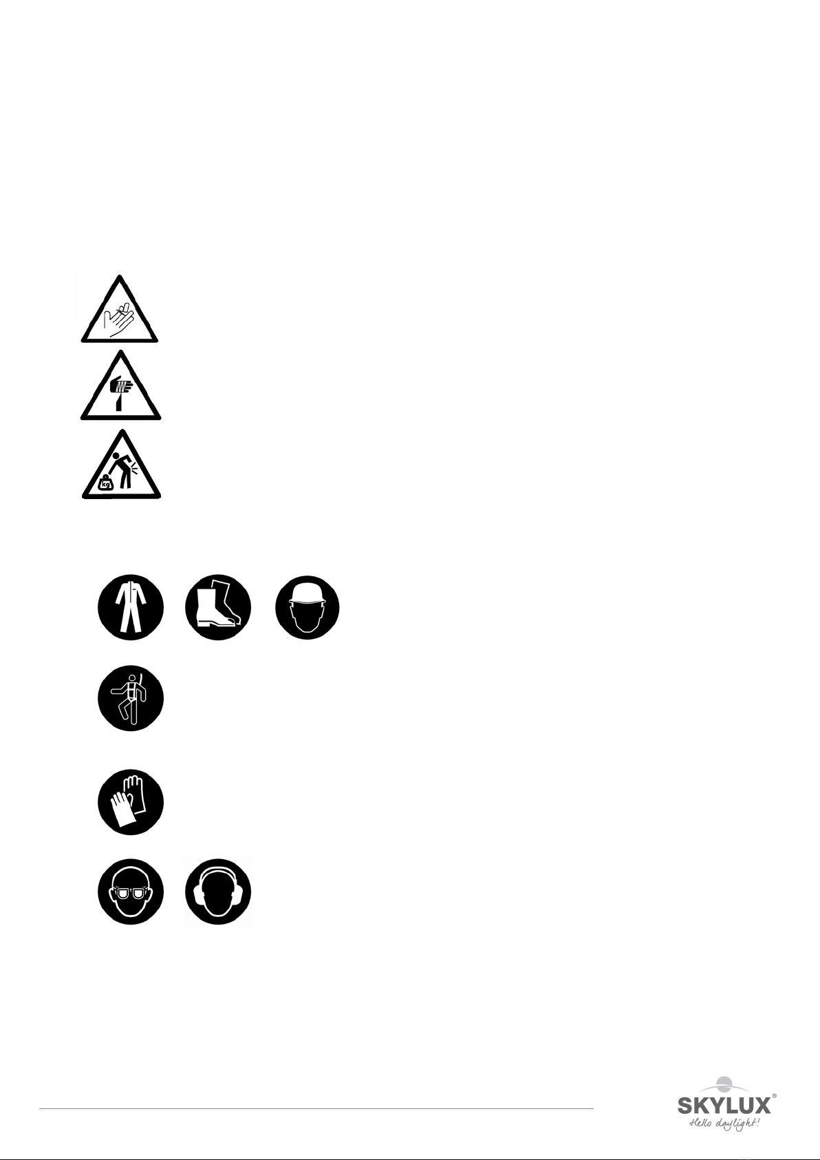
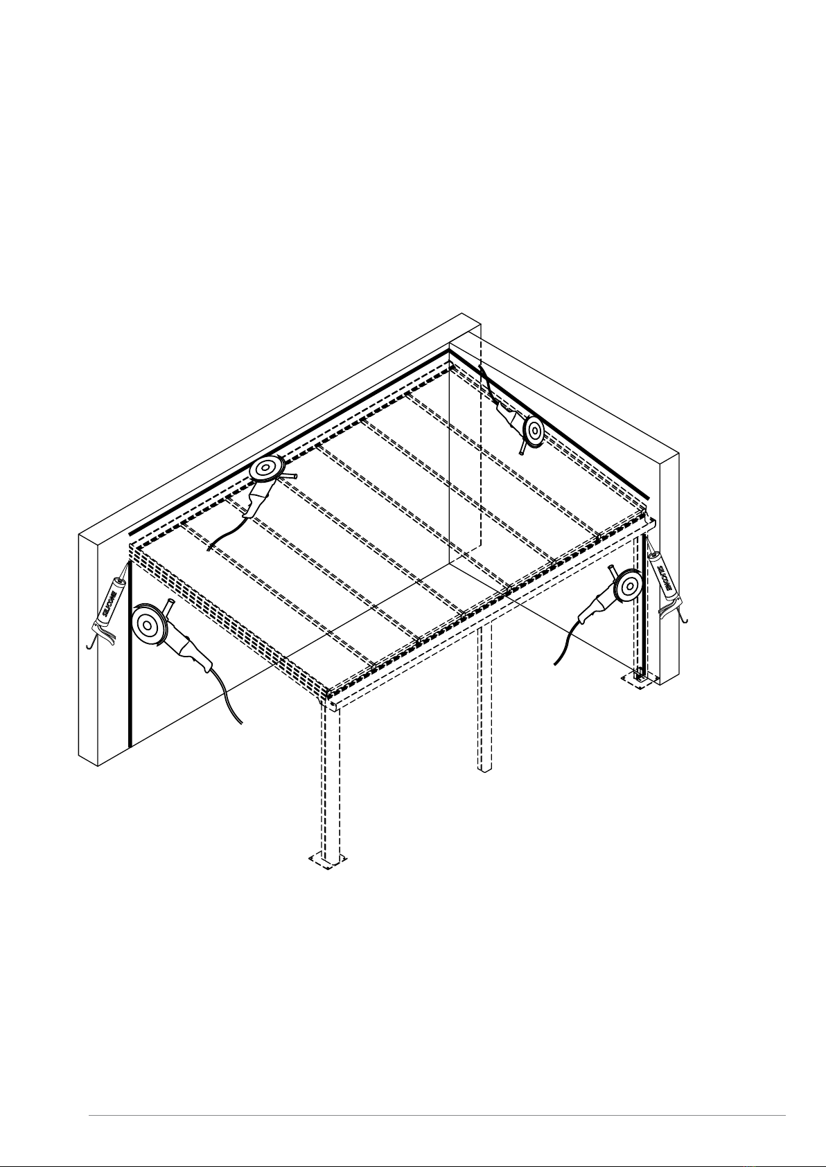
Safety
Take the necessary and required safety precautions, such as safety nets and lifelines when installing from the
outside, safety goggles, gloves, hard hat, etc.
Do not step on the glass.
Falling from height
• When using ladders to go on the roof:
- Ladder in good condition?
- Set up correctly at an angle of 75°?
- Secured below and on top against moving?
- Don’t take heavy material with you on the ladder (3-point contact rule)! If possible,
use a crane to lift the material.
• If you are going on the roof, make sure there is a walking surface that is wide enough and that
supports on the beams of the lower structure.
•When using an aerial work platform: always wear and secure your harness (mandatory)! Leaving
the cage is forbidden.
• Never walk backwards on a roof, always walk forwards.
• Make sure there’s enough light in the working zone.
Low-hanging obstacles and falling loads
• Forbidden to walk under or within a radius of 1 m of a hanging or lifted load.
• Demarcate the danger zone below the zone where there is a risk of material falling down
during the installation of the veranda.
• It’s prohibited to enter these danger zones during construction.
Crushing hazard
• All working tools are in good condition, provided with a valid CE label and all necessary safety
regulations. These cannot be removed.
• People who use these working tools are educated for this purpose. Protections are always
present on all working tools. They are in good condition and need to be set correctly.
Tripping/falling
•Safety is key and it begins with order and tidiness. Clean everything immediately, leave nothing
lying around.
• Trash needs to be sorted.
• Be cautious with electric cables (danger of tripping/falling). Never walk backwards!
• Make sure there’s enough light in the working zone.
20/11/2020 3/88
E_MH_Installation_instructions_Skylux_Climax
Sharp objects
• Make sure your fingers/hands are not pinched and watch out for cuts while handling veranda
parts.
• Be careful where you put your hands during the installation.
• Wearing cut-resistant gloves is mandatory.
Ergonomics
• Always lift loads correctly: bend your knees, move your feet instead of forcing your spine, lift
as close to your body as possible.
• Parts of more than 25 kg must be lifted with at least 2 persons.
Personal protective equipment
• Work clothes, safety shoes and helmet are mandatory for everyone.
• Lifeline and harness are mandatory if the edge is not secured enough or if there are no safety nets below the
veranda roof. They are also necessary when using an aerial working platform.
• Use gloves when handling veranda parts.
• Safety glasses and hearing protection are mandatory when using saws / grinders.
Always perform a Last Minute Risc Analysis!
If in doubt: STOP! Do not take unnecessary risks. Ask your supervisor if needed.

E_MH_Installation_instructions_Skylux_Climax 20/11/2020
4/88
SAFETY p. 2 3
CONTENTS p. 4 5
OVERVIEW OF CLIMAX PROFILES AND PARTS p. 6 10
GENERAL INSTALLATION TIPS p. 11 20
MEASURING YOUR CLIMAX PITCHED ROOF p. 12 13
MEASURING YOUR CLIMAX SADDLE ROOF p. 14 15
PREPARATION p. 16
GENERAL TIPS AND MAINTENANCE
INSTRUCTIONS p. 17 - 18
PLAN OF CONSERVATORY ROOF WITHOUT
THERMAL BRIDGE p. 19
PLAN OF CONSERVATORY ROOF WITH
THERMAL BRIDGE p. 20
SPECIFIC INSTALLATION TIPS FOR THE CLIMAX
SYSTEM WITHOUT THERMAL BRIDGE p. 21 41
POSTS p. 22 23
GUTTER p. 24 27
HINGE PROFILE p. 28
WALL PROFILE p. 29
SUPPORTS AND SIDE SUPPORTS p. 30 33
GLAZING p. 34 35
FINISH p. 36 41
SPECIFIC INSTALLATION TIPS FOR THE CLIMAX
SYSTEM WITH THERMAL BRIDGE p. 42 67
POSTS p. 43 44
GUTTER p. 45 48
HINGE PROFILE p. 49
WALL PROFILE p. 50
SUPPORTS AND SIDE SUPPORTS p. 51 55
GLAZING p. 56 57
FINISH p. 58 67
Table of contents

20/11/2020 5/88
E_MH_Installation_instructions_Skylux_Climax
SPECIFIC INSTALLATION TIPS FOR THE CLIMAX
SADDLE ROOF SYSTEM p. 68 74
PREPARATION OF THE RIDGE PROFILES OF
A SADDLE ROOF p. 69 70
INSTALLATION OF THE RIDGE PROFILES OF
A SADDLE ROOF p. 71
PREPARATION OF THE TIE BAR FOR THE
SADDLE ROOF p. 72
INSTALLATION OF THE TIE BAR FOR THE
SADDLE ROOF p. 73
SIDE FINISH OF THE SADDLE ROOF p. 74
ANNEX p. 75 84
LOAD GRAPHS p. 76 80
LOAD GRAPHS FOR ROOFS WITH
PLASTIC SHEETS p. 77 78
LOAD GRAPHS FOR ROOFS WITH
GLASS p. 79 80
SPECIFIC INSTALLATION TIPS FOR POSTS
WITH GD2 p. 81
SPECIFIC INSTALLATION TIPS FOR
CONNECTING GLAZING p. 82 83
GLAZING THICKNESS TABLE p. 84
Table of contents
E_MH_Installation_instructions_Skylux_Climax 20/11/2020
6/88
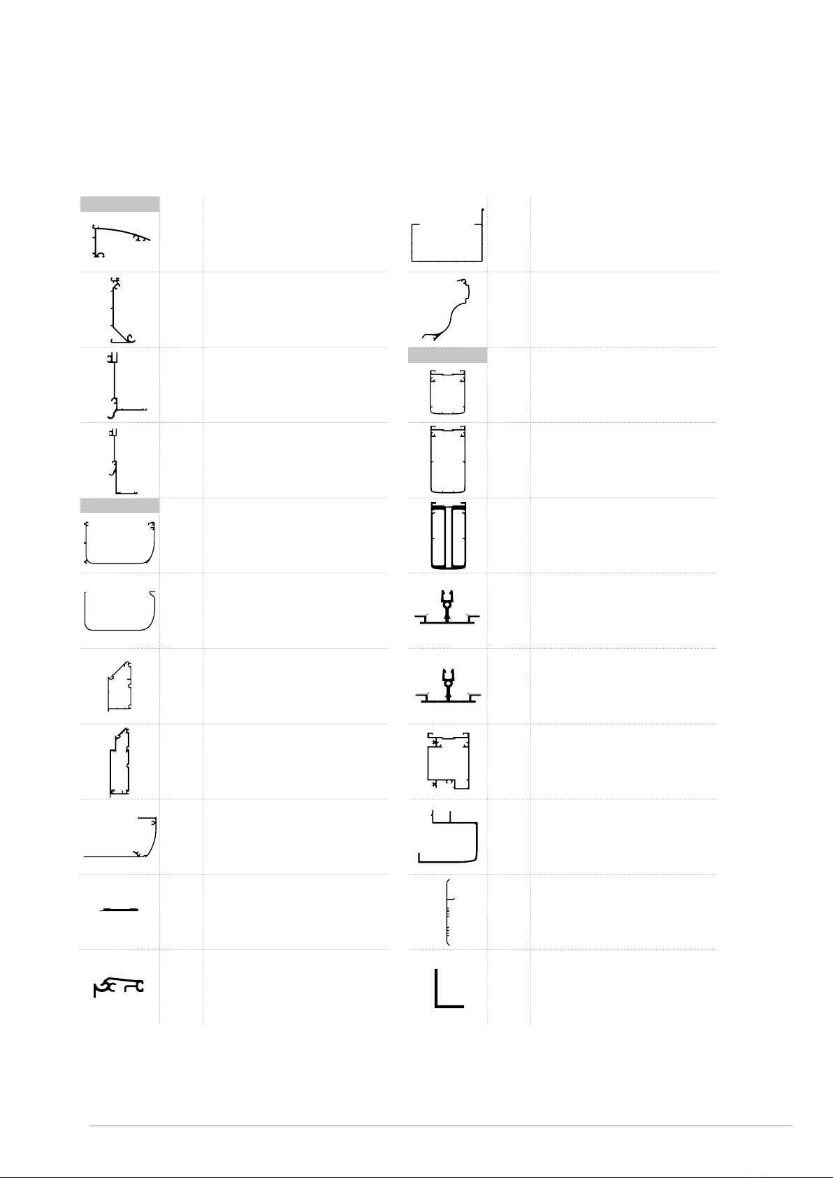
Overview of Climax profiles and parts
MT WALL TOP
MB WALL BOTTOM
S1 HINGE
S2 HINGE
G GUTTER
GI
GI 0
GI 90
GI 120
GI 150
GI -90
INSIDE GUTTER FOR G
CONNECTION FOR G
OUTSIDE CORNER PIECE 90°
OUTSIDE CORNER PIECE 120°
OUTSIDE CORNER PIECE 150°
INSIDE CORNER PIECE 90°
GD 1 GUTTER SUPPORT
GD 2 GUTTER SUPPORT
GD2C COVER FOR GUTTER SUPPORT GD2
GDP THERMAL BREAK GD2
SB HINGE BOTTOM
WALL
GUTTER
G120A GUTTER 120 A
GR RAISED PROFILE FOR GUTTER
D1 SUPPORT
D2 SUPPORT
D3 SUPPORT
TP THERMAL SUPPORT
TPG THERMAL SUPPORT FOR GLASS
ZD SIDE SUPPORT
ZD2B SIDE SUPPORT D2 CLIPS
ZDC SIDE SUPPORT COVER 16, 25, 32 MM
L432 L-FINISH SIDE SUPPORT
L END PROFILE FOR GLASS
SUPPORTS

20/11/2020 7/88
E_MH_Installation_instructions_Skylux_Climax
Overview of Climax profiles and parts
L632 L END PROFILE FOR GLASS
V642 STEEL TUBE 60X40X2 GALVA
L16P ALUMINIUM SIDE PROFILE 16, 25,
32 MM
CL16 ALUMINIUM CLIP 16 MM
CL32 ALUMINIUM CLIP 25/32 MM
CLL SIDE CLIP 16, 25, 32 MM
CLSB BASE SCREW-IN CLIP
CLST TOP SCREW-IN CLIP FOR 8 TO 34 MM
CLSL TOP SCREW-IN SIDE CLIP
P POST PART 110/50
PC POST CLIP FOR P
POSTS
PCB POST CLIP BASE FOR P
98 POST 50/100
97A POST CLIP BASE FOR POST CLIP
WITHOUT COAT
97B POST CLIP
100 POST 100/100
C1CX
COEX SEAL FOR WALL TOP WHITE/
BLACK
COEX SEAL FOR WALL TOP GREY/
BLACK
C12 SUPPORT CORD FOR C1CX
C2CX COEX SEAL WHITE/BLACK FOR TP-TPG
COEX SEAL GREY/BLACK FOR TP-TPG
C5 SEAL (GREY) FOR SHEET SPACER OR
SIDE SUPPORT
C8 SEAL (GREY) FOR CL16, CL32 AND
CLSB
CY10 SEAL (GREY) FOR CL16, CL32 AND
CLSB FOR GLASS
SEALS

E_MH_Installation_instructions_Skylux_Climax 20/11/2020
8/88
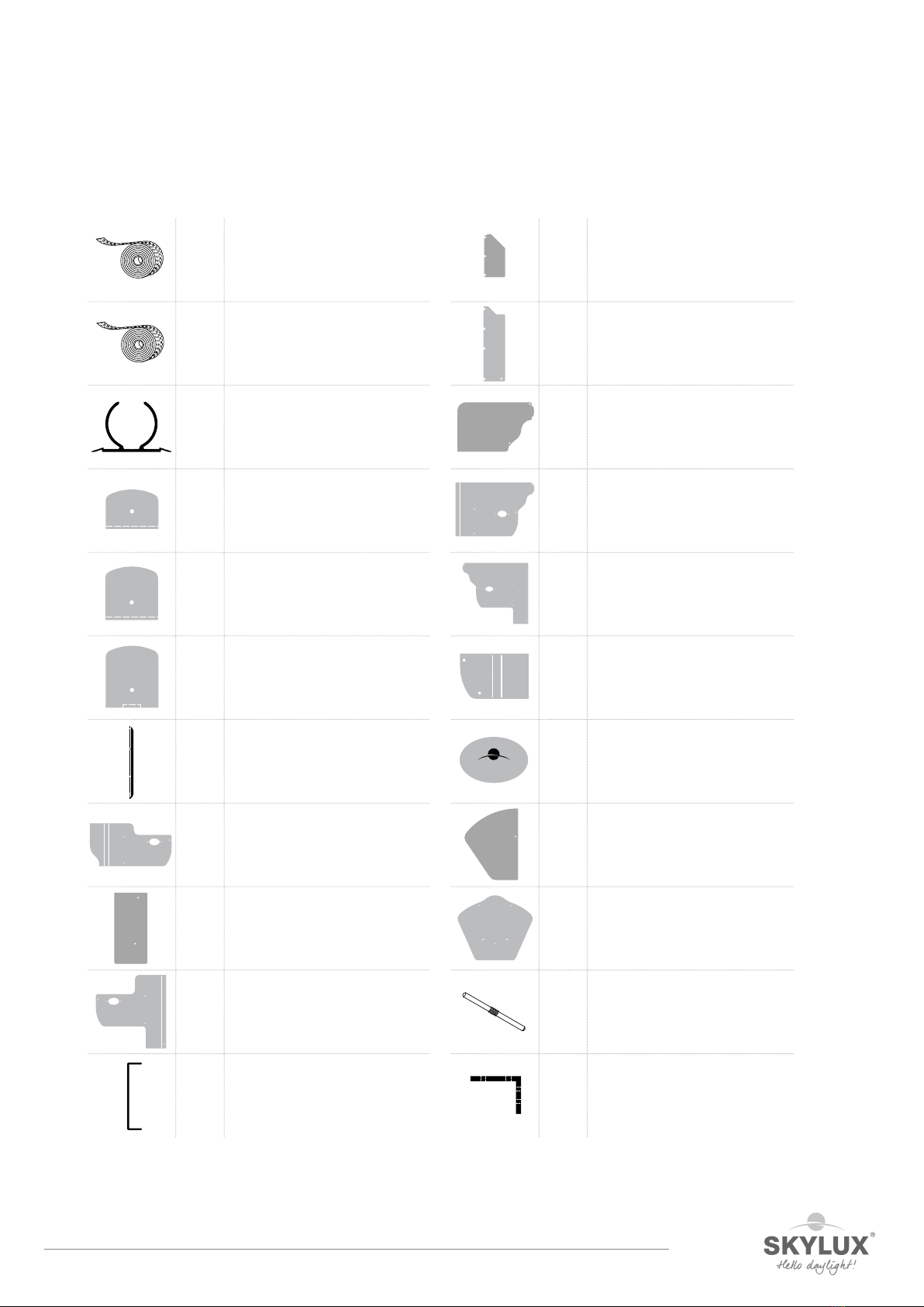
Overview of Climax profiles and parts
C11CX COEX SEAL FOR GUTTER/RIDGE
WHITE/BLACK
C31 SUPPORT SEAL FOR GLASS
A1 SPACER A1
A2 SPACER A2
GVT TOP PROFILE FOR GLASS
CONNECTOR
GVB BOTTOM PROFILE FOR GLASS
CONNECTOR
Y10 ADAPTOR PROFILE 8 MM FOR 10 MM
SHEET
Y25 ADAPTOR PROFILE 9 MM FOR 25 MM
SHEET
Y32 ADAPTOR PROFILE 15 MM FOR 32 MM
SHEET
Y16A RAISED PROFILE ALUMINIUM 16 MM
Y16P THERMAL BREAK ABS 16 MM
ACCESSORIES
U16P REINFORCED PVC END PROFILE 16
MM WHITE
U25P REINFORCED PVC END PROFILE 25
MM WHITE
U32P REINFORCED PVC END PROFILE 32
MM WHITE
U16A ALUMINIUM END PROFILE 16 MM
U32A ALUMINIUM END PROFILE 32 MM
U16 PRE-DRILLED ALUMINIUM END
PROFILE 16 MM
U32 PRE-DRILLED ALUMINIUM END
PROFILE 32 MM
BT16 CLOSED PLASTIC TAPE 10 AND 16 MM
WITH GUARANTEE
BT25 CLOSED PLASTIC TAPE 25 MM WITH
GUARANTEE
BT32 CLOSED PLASTIC TAPE 32 MM WITH
GUARANTEE
BB16 PERFORATED PLASTIC TAPE 16 MM
WITH GUARANTEE
20/11/2020 9/88
E_MH_Installation_instructions_Skylux_Climax
Overview of Climax profiles and parts
BB25 PERFORATED PLASTIC TAPE 25 MM
WITH GUARANTEE
BB32 PERFORATED PLASTIC TAPE 32 MM
WITH GUARANTEE
K STRAIGHT CONNECTOR
S163 STOP 16/3
S323 STOP 32/3
S383 STOP 38/3 FOR GLASS
ZDCS END PIECE FOR SIDE SUPPORT
COVER
GAS1 GUTTER SLIDE END FOR G+GD
GAS2 GUTTER SLIDE END FOR GD
GAS3 GUTTER SLIDE END FOR GD2 + G
G120AS GUTTER SLIDE END FOR G12OA
GAP1 THERMAL END PANEL FOR GD1
GAP2 THERMAL END PANEL FOR GD2
GRS1 GUTTER SLIDE END FOR GR ON G120A
GRS2 GUTTER SLIDE END FOR G+GD+GR
GRS3 GUTTER SLIDE END FOR GD2 + G + GR
GDCA SLIDE END FOR GD2C
LOGO OVERFLOW COVER FOR GUTTER
SLIDE END
MAS WALL SLIDE END FOR MT+MB
NASZ RIDGE SLIDE END SADDLE ROOF
909 CONNECTING PIN
GDC SUPPORT BRACKET FOR GUTTER
SUPPORT
CLIMAX

E_MH_Installation_instructions_Skylux_Climax 20/11/2020
10/88
Overview of Climax profiles and parts
NCZ SUPPORT BRACKET FOR SADDLE
ROOF RIDGE
PV BASE PLATE FOR POST
PU U-TOP, BOTTOM FOR POST P AND
BASE PLATE PV
BMR STAINLESS STEEL BOLT, NUT AND
SPRING RING M8
UT10 U-TOP, BOTTOM FOR POST 100 AND
BASE PLATE PV
UT98 U-TOP, BOTTOM FOR POST 98 AND
BASE PLATE PV
GC OUTLET + SWIVEL Ø 80 mm
BUGS
WUGS
UNIVERSAL GUTTER SPOUT +
OUTLET GUTTER SPOUT
8423 CENTRAL DRAWING RING
8420 CENTRAL ROSETTE COVER
8425 RIDGE FIXATION
8424 END-PIECE FOR THREADED BAR
8426 EYE BOLT M10 x 50
8421 TUBE PULLER SET
ZSB
ZSG
ZSC
SELF-DRILLING STAINLESS STEEL SCREW
(NON-COATED)
SELF-DRILLING STAINLESS STEEL SCREW
(COATED)
SELF-DRILLING STAINLESS STEEL SCREW
WITH SEALING
6,3 x 25 SELF-DRILLING SCREW 6,3 x 25 mm
PS48 PARKER STAINLESS STEEL SCREW 4.8
x 25 mm
PST PARKER SCREW 4.8 x 13 mm
TX25
10
PH2
TX25

20/11/2020 11/88
E_MH_Installation_instructions_Skylux_Climax
General installation tips
Please read this manual carefully.
The installation must be carried out by people with sucient technical knowledge and experience in the area of
conservatory installation. The installer must take the required safety measures into account during the installation
such as the use of scaolding and personal protection equipment (safety shoes, helmet (i.e. a hard hat), gloves,
safety goggles, etc.) to ensure the work is carried out in a safe environment. During installation, please make sure
that the necessary precautions have been taken to ensure the stability of the unfinished construction.
Fixing material
The selection of required fixing material is dependent on the foundation or the walls. Check whether the
foundation and the walls on which the structure is to be anchored have a sucient load-bearing capacity. The
installer is responsible for the assessment of the appropriate fixing materials for the load and foundation on which
the structure is to be fixed. Please contact your fixing material supplier or specialised engineering consultants in
case of doubts. Skylux cannot be held liable for the installation or the fixing materials used.
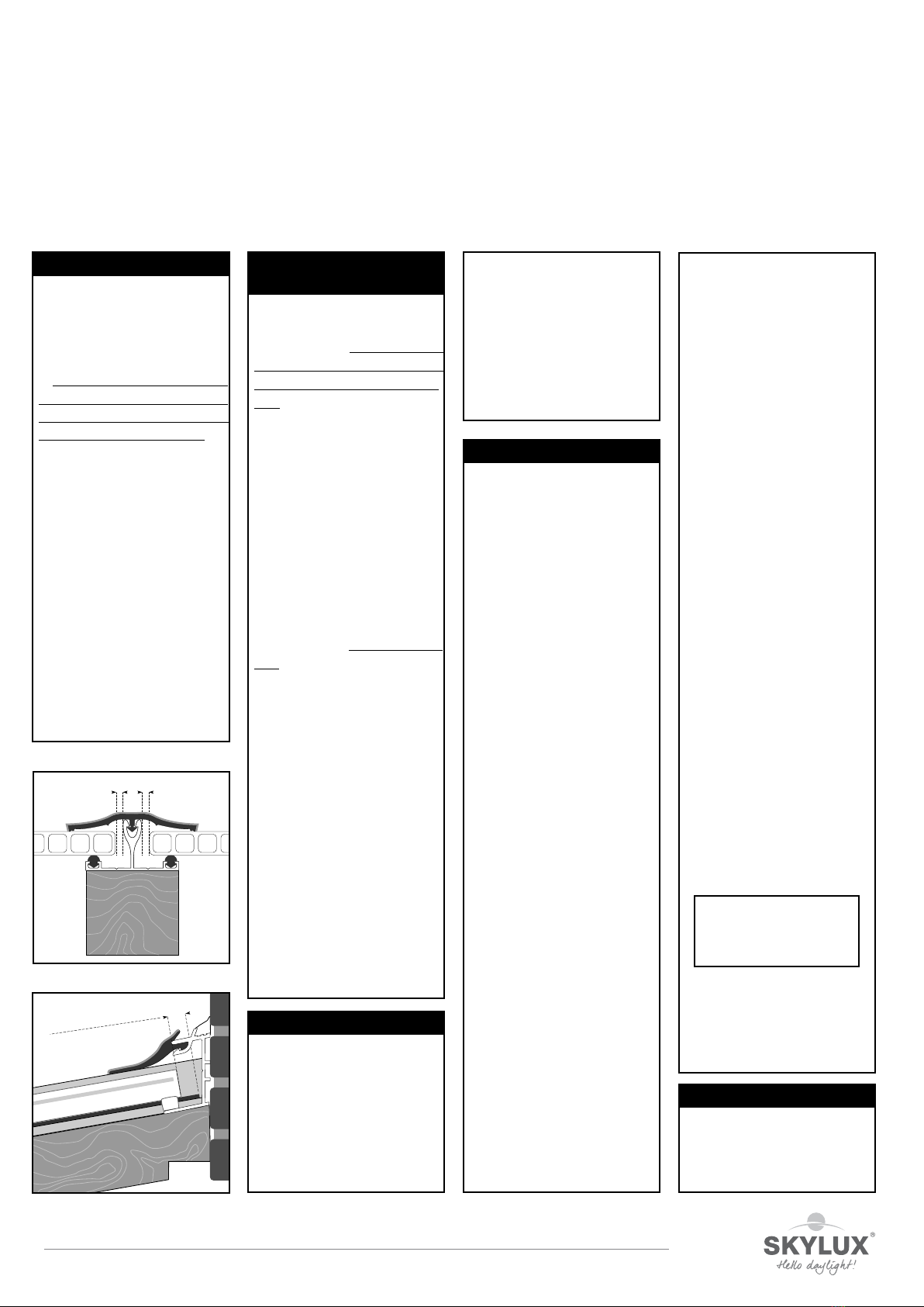
Seal installation
A distinction is made between push-in seals and slide seals.
The seal of a push-in seal is pushed into the profiles. The C2CX, C12, C8, CY10, C11CX and C31 seals are push-in
seals.
Slide seals C1CX and C5 are slid into the profiles.
Seals C1CX and C2CX are equipped with an anti-stretch wire that prevents the seal from being stretched during
installation. This technology ensures that the seal cannot shrink after installation.
Avoid the use of silicone and detergent when installing the seals. Plastic sheets can be damaged by these products.
Plastic sheets can result in settlement noise due to temperature fluctuations. This will not aect the guarantee and
will not be accepted as a claim.
Terms, conditions and guarantee
The guarantee is void when the installation instructions provided below are not followed. Not following the
instructions and/or using other parts may have an adverse eect on the safety and life cycle of the product.
Deviations are not permitted without the written permission from the manufacturer. The installer must take the
specified span values in relation to the glazing and load (snow and wind) according to the applicable standards into
account.
The load graphs that you will find in this manual on pages 76 - 80 are only indicative. Contact the manufacturer,
architect or engineering consultant for porch roofs outside the normal range.
The manufacturer reserves the right to make technical changes without prior verbal or written notification.
Skylux reserves the right to change this manual without prior notification. Changes with regard to the installation
requirements or to the product will not mean a right to any compensation or exchange of parts.
The latest version of this manual can be consulted by visiting www.skylux.be.
Climafast
The CLIMAFAST calculation application, free of charge by Skylux. You will receive information on how to log on
and download the Excel version of the application upon request. With Climafast you can determine the price of
your Climax roof. An overview of profiles, lengths, parts, permitted loads, etc. is provided for each project. The
aim of this application is to inform the user.
Skylux reserves the right to change the Climafast calculation application without prior notification. The results
of the calculations are not final and will not mean that there is a right to compensation. The latest version of the
calculation application can always be downloaded from www.skylux.be.

E_MH_Installation_instructions_Skylux_Climax 20/11/2020
12/88
Measuring your Climax pitched roof
Measurement
Determine height dierence H.
Height dierence H is the dierence between the bottom side of wall profile MB and the bottom surface of the
gutter combination. The stop lip for the window is not included in the calculation.
Height h depends on the thickness of the glazing and the angle of gradient where 1 or multiple thermal bridges are
to be slid in.
Determine the depth (Fig. 2, page 13)
Measure from the wall to the inner side of the support post or the window under gutter support GD1/GD2 to
determine roof depth D. The additional depth of gutter G + Y16P + gutter support GD is 233 mm for a Climax.
thermal bridge. The depth for a Climax without a thermal bridge with gutter support GD1 or GD2 is 225 mm.
Determine the width B (Fig. 2, page 13)
Width B of the Climax is the distance between the outer side of the side supports ZD. An additional 12 mm per side
support must be added for applications with a side support cover ZDC. The total conservatory width with 2 ZDCs
is, therefore, 24 mm wider. If the Climax is installed between two walls and a gutter with screwed-on gutter end
pieces is used, you can deduct 5 mm per side from width B. This is because the screws for the gutter end piece
require additional width and additional clearance is recommended.
These measurements can be used to calculate all other measurements using the Climafast calculation application
that is made available free of charge by Skylux. We strongly recommend the use of the calculation application.
All possible exceptions are taken into account. The correct cutting lengths are provided and only correct
combinations are suggested. The list of measurements for sizing is always provided with the materials.
D
H
h
B
H
D
233 mm
Y16P
Sheet thickness (mm)
Slope ° 5-35 36-45 5-20 21-35 36-40 41-45 5-30 31-34 41-45
Number of Y16P 1 2 1 2 3 4 2 3 4
Heigth h (mm) 156 172 156 172 188 204 172 188 204
0-16 17-25
Number of Y16P in relation to the sheet thickness and angle of slope
26-34

20/11/2020 13/88
E_MH_Installation_instructions_Skylux_Climax
Measuring your Climax pitched roof
Installing the Climax post and the Climax PV base plate.
- Determine point O1.
- Determine O2. The distance O1- O2= conservatory width “B”.
- Draw a line with chalk using the 3/4/5 rule and determine point
P1. The distance O1- P1is the depth = D (refer to item 3 below).
- Repeat the same calculations for P2.
- Measure the distance (P1- P2), which must be equal to
(O1- O2) as an additional check.
- The base plate can be slid through the slotted holes in order
to position the base plate properly.
- The U for the base plate can be moved 20 mm either way to
allow proper adjustment.
* 95 mm in combination with post P /
100 mm in combination with post 98 or post 100
The 3/4/5 rule.
- Determine the auxiliary point C1based on O1at a distance
of 4 metres
- Use a 3 metre string and a piece of chalk to draw a circle from
point O1.
- Use a 5 metre string to draw a circle from point C1.
- The 2 circles intersect at C2.
- Line O1- C2should be at a perfect right angle to your wall
(line C1-O1).
The dierence in height H and depth D for the veranda.
HM= The height from the floor and the bottom side of the
wall bottom (MB) measured at the back of the veranda.
HN= The slope of your veranda floor.
HG+ HN= Installation height for the bottom side of gutter
support GD1 or GD2. This is also the height for the
windows or the length of the posts.
H = HM- HG
h = Wall profile height
H
HMHG
HN
D
h
D
O2
B
O1
P1
P2
C2
C1
3 m
4 m
5 m
D
20 mm
300 mm
300 mm
P1
100 mm
95 mm / 100
m
*
95 mm / 100 mm
*
P2
100 mm
1
2
3

E_MH_Installation_instructions_Skylux_Climax 20/11/2020
14/88
Measuring your Climax saddle roof
Measurement
The ridge of the saddle roof must be attached to at least one wall.
Determine height dierence H. Height dierence H is the dierence between the bottom side of wall profile MB
and the bottom surface of the gutter combination. The stop lip for the window is not included in the calculation.
Height H must be equal at the left and the right.
Height h’ depends on the thickness of the glazing and the angle of gradient where 1 or multiple thermal bridges
are to be slid in.
Determine the depth (Fig. 2, page 13)
Measure the distance from support post P or the windows that will be installed under gutter supports GD1/
GD2 to determine roof depth D. The left depth DL may be dierent from the right depth DR when the roof is
asymmetrical. The maximum depth D is 6 m. The additional depth of gutter G + Y16P + gutter support GD equals
233 mm for Climax with a thermal bridge. The depth with gutter support GD1 or GD2 is 225 mm for Climax
without a thermal bridge.
Determine the width B (Fig. 2, page 13)
Width B of the Climax is the distance between the wall and the exterior of the side support. An additional 12
mm must be added for applications with a side support cover ZDC. The total conservatory width with 2 ZDC is,
therefore, 12 mm wider. If the Climax saddle roof is installed between two walls and a gutter with screwed-on
gutter end pieces is used, you can deduct 5 mm per side from width B. This is because the screws for the gutter
end piece require additional width and additional clearance is recommended.
These measurements can be used to calculate all other measurements using the Climafast calculation application
that is made available free of charge by Skylux. All possible exceptions are taken into account. The correct cutting
lengths are provided and only correct combinations are suggested. The list of measurements for sizing is always
provided with the materials.
h’ 164 mm 156 mm
H
D
233 mm 233 mm
B
H
DR
DL
Y16P
DR
DL
Sheet thickness (mm)
Slope ° 5-35 36-45 5-20 21-35 36-40 41-45 5-30 31-40 41-45
Number of Y16P 121234234
Heigth h (mm) 156 + 8 172 + 8 156 + 8 172 + 8 188 + 8 204 + 8 172 + 8 188 + 8 204 + 8
26-34
Number of Y16P in relation to the sheet thickness and angle of slope
0-16 17-25

20/11/2020 15/88
E_MH_Installation_instructions_Skylux_Climax
Measuring your Climax saddle roof
Embedding the Climax post and the Climax base plate PV.
- Select point O1.
- Determine O2. The O1- O2distance = conservatory depth “D”.
- Draw a chalk line using the 3/4/5 rule and determine point P1.
The O1- P1distance is the width = B (See item 3 below).
- Repeat the same calculations for P2.
- Measure the distance (P1- P2), which must be equal to (O1-
O2) as an additional check.
- The base plate can be slid through the slotted holes in order
to position the base plate properly.
- The U for the base plate can be moved 20 mm either way to
allow proper adjustment.
* 95 mm in combination with post P /
100 mm in combination with post 98 or post 100
The 3/4/5 rule.
- Determine the auxiliary point C1based on O1at a distance
of 4 metres
- Use a 3 metre string and a piece of chalk to draw a circle from
point O1.
- Use a 5 metre string to draw a circle from point C1.
- The 2 circles intersect at C2.
- Line O1- C2should be at a perfect right angle to your wall
(line C1-O1).
The dierence in height H and depth D for the saddle roof.
HM= Height between the floor and the bottom side of the
ridge to wall bottom MB measured at the back against
the wall.
HG= Installation height of the bottom side of gutter support
GD1 or GD2. This is also the height for the windows or
the length of the posts.
H = HM- HG
h’ = Saddle roof wall profile height
HMHG
D
DLDR
H
h’
D
1
O2
D
O1
P1
P2
C2
C1
3 m
4 m
5 m
B
20 mm
300 mm
300 mm
95 mm /
100 mm
*
95 mm /
100 mm
*
P2
100 mm 100 mm
P1
2
3
E_MH_Installation_instructions_Skylux_Climax 20/11/2020
16/88
Preparation
The Climax roof can be delivered cut-to-size to reduce the installation time.
The seals and certain other components are, when possible, fixed onto or into the profiles for the preinstalled roof
system.
Walls
Check that the walls, against which the structure is to be installed, are:
- Suciently load-bearing to anchor the roof.
- Free of obstacles such as water drains, window sills, etc.
Make a slot in the walls against which the conservatory roof is to be installed.
Install a lead slab or zinc flashing. We refer to page 10: Measuring your Climax pitched roof. Height = first joint
above HM + H and at most 60 mm above the wall profile.
For structures with a thermal bridge (for example, a closed veranda) we recommend making a slot in the walls
where the profile can be installed.
Floor
Ensure that the foundation can carry the load. Have an architect determine the required foundation. Implement
measures to remove rainwater from the roof.
Precautions
Protect the finished profiles against scratches and dents during installation.
20/11/2020 17/88
E_MH_Installation_instructions_Skylux_Climax
uNearly all silicone products affect
the polymethyl methacrylate or poly-
carbonate sheets. Purchase silicone
types that are safe for polymethyl
methacrylate or polycarbonate pro-
ducts (guarantee certificate).
uThe fumes from this putty may
never evaporate in the slots of the
sheet. The ventilation openings as well
as the sides of the end profiles may
not be closed off. The silicone should
always be allowed to release fumes
freely.
uSome seals contain softening agents
(as used in certain types of rubber,
PVC, polyurethane, etc.) that may
cause small cracks. Use only approved
seals.
uDo not use black or dark-coloured
seals to prevent heat accumulation.
uA lead slab may be placed on the
seals but may not rest against the
sheets.
uSome paints, varnishes and wood
protectors affect the polymethyl
methacrylate or polycarbonate sheets.
Never use lubricants to put the seals
into the profiles.
uNever spray insecticide directly on
to the sheets. Synthetic sheets can be
damaged by these products.
2. SILICONE, SEALS AND
WOOD PROTECTORS
uObserve the safety instructions
that apply to work on roofs.
Polycarbonate sheets: Very
IMPORTANT! The side which is
protected against UV radiation
must always be installed facing
the exterior or the sky. The “sun
side” is indicated on the protec-
tion film.
uThe plastic tape or the provisional
aluminium tape will only ensure the
sheets are free from dust while being
shipped. These should be removed!
Adjusted aluminium tape or end pro-
files must be used.
uThe load-bearing structure must
be strong and stable. (See the regu-
lations that apply to the timber and
metal construction industry.) Cross
supports may be required depending
on the type of sheet used. Only spe-
cific maximum lengths may be used
without a cross support for each
type of sheet taking into account
the loads of 500 N/m2or 750 N/
m2, respectively (see the technical
plastic sheets information sheet).
uPergotop/Pergotop-soft sandwich
panels are only adapted in combina-
tion with Skylux screwable clips.
uHeat accumulation: the top side
of the load-bearing structure that is
turned towards the sheets must be
WHITE reflective.
4. INSTALLATION
Synthetic sheets can expand or shrink
when there are temperature fluctua-
tions. The following tips should be
taken into account:
uEnsure there is 5 mm clearance
lengthwise for each sheet meter and
ensure there is 10 mm clearance
(5 mm on each side) widthwise, for
example, a 3000 mm sheet must
have a clearance lengthwise of 1.5 cm.
uNever block the sheet lengthwise
or widthwise. Always ensure sufficient
clearance.
uNever stick the sheet using silicone
(even when it does not damage syn-
thetic materials). It would prevent the
expansion and shrinkage of the sheets.
uThe sheet is blocked at the bot-
tom end to prevent it from sliding. The
clearance must, therefore, be pro-
vided at the top.
1. CLEARANCE
5 mm 5 mm
uApply white dispersion paint (diluted
in water or paint without solvents) or use
preferably aluminium tape. Attention:
Let the paint dry after painting the
load-bearing structure! Continue with
the installation of the sheets after the
paint has dried. The synthetic sheets may
NEVER be installed directly on to tim-
ber structures.
uDo not place roof tiles directly on
the sheets! Leave a space of at least
10 mm between the sheets and the
roof covering.
uUse a special weather stripping (seal
C6) for sealing the opening between
the plate and the gutter beam. Do not
seal using sealant or fill with PU foam.
uWe formally recommend not add-
ing a ceiling under the acrylic sheets
(PMMA). Any used sun blinds or
other finish under the sheets should
be at least 120 mm from the roofing
sheet. These may not have insulation
properties and should have a reflect-
ing colour. The polycarbonate sheets
(PC) do not require any specific pre-
cautions.
u
WIDTH DISTRIBUTION
OF THE SHEETS:
RECOMMENDED:
standard
sheet width with an adapter for the 2
outer sheets. This is especially impor-
tant for the S5P heat-stop sheet.
NOT RECOMMENDED:
in equal sections with sized sheet
widths. Take the standard sheet width
into account. We formally advise
against sizing multiple-layer sheets.
The closed off sides are
one of the factors that
determine the sheet
strength!
uFollow the installation instructions
provided by the glass manufacturer
when including the installation of
glass!
5. GLASS
uClean the sheets annually using
lukewarm rainwater. Dissolve a little
household soap (neutral) in the water
if required (no detergent!!). Never use
solvents or abrasive products.
uDo not rub dry (may cause
scratches).
uSimply rinse.
3. MAINTENANCE
Space for expansion
uClean the surfaces/profiles min.
1 a year with cold water and a mild
soap. Rinse well with plenty of
water.
Never use solvents or abrasives!
A good cleaning is necessary to
avoid the profiles from growing dull
and dirty by the UV light!
General tips and maintenance instructons
The qualitative and technological level of the multiple layer plastic sheet is high. We provide a few important tips for problem-free
installation. Please pay special attention to the following: Space for expansion/silicone and wooden protection/seals.
E_MH_Installation_instructions_Skylux_Climax 20/11/2020
18/88
SILICON
E
6. DRAINAGE AND CONDENSATION
uInstall the sheets with inclination or
vertically, never horizontally (unless
interior use).
uMinimum inclination: 10° (18 cm
per meter) or more.
uThe direction of the sheet canals
must always go along with the roof
inclination.
7. SHEET DIRECTION
°°
° °
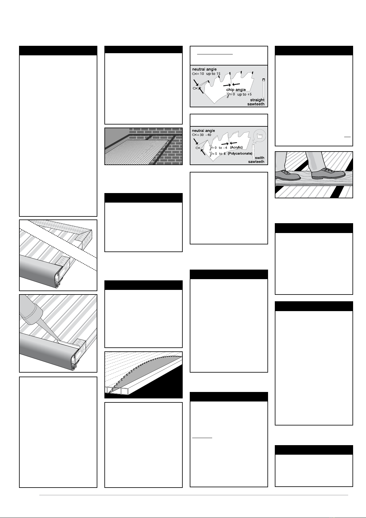
uType of saw blade:
1. hard metal (for ca 50 m/s)
uMake sure that the bottom NEVER
stands in water (moss and algae).
uCondensation in the canals is not
100% inevitable (physical phenome-
non).
Acrylic and polycarbonate are very
less gas- and dampproof. The charac-
teristics of the material and the gua-
rantee are not diminished because of
this. An appropriate sealing is recom-
mended.
uAlways use a grease pencil to make
notes on the protection film (felt pen
is difficult to remove).
uTo ensure a fest clamping during the
sawing, you should always make sure
that a raised rib is as near as possible
by a sawed edge.
9. SAWING AND DRILLING
uWhen sawing, use a hard metal saw
(widea) with high rotation speed. Saw
slowly and by preference with one
move. Use new or sharpened saw bla-
des. Make sure the sides are always
smooth.
ATTENTION: The basis on which the
sheets are sawn, must be stable and
vibration-free. The sheets must not
move during sawing. The saw blade
must slightly reach out of the sheet.
uRemove all dust and sawing rests
from the canals with pure compressed
air or a powerful vacuum cleaner.
uOnly remove the protection film
after installation to avoid scratches.
uDrilling is strongly advised against.
However, if unavoidable, provide with
grooves (shrinking and dilatation).
°°
°°
°°
2. HSS (not more than 40 m/s)
uAvoid direct sunlight on piled
sheets.
uIf you pile the sheets outside, cover
the sheets with white polyethyl foil.
Always keep the synthetic friendly
tape as sealing on the front sides of
the sheets.
uThe sheets must not be piled direct-
ly on the ground. Use appropriate pal-
let boards.
10. PILING
uNever walk or kneel directly on the
sheets. Always use solid timber boards
underneath. Make sure these boards
are supported by the timber construc-
tion.
uMulti-walled synthetic sheets with
thin walls and a high insulating struc-
ture in the sheet, are sensitive to foot,
knee and other impressions at the
surface. Please take enough precau-
tions during transport and installa-
tion. Impressions in the sheet are not
covered by the guarantee.
12. REMEMBER
uAs we already mentioned several
times, synthetic sheets shrink and
dilate under the influence of tempe-
rature fluctuations. When they move
with regard to the roof construction,
there can be some creak noises. There
is no danger for the sheets if they
have been installed according to the
installation instructions.
u
Screwed clipses cause more creak
noises with synthetic sheets
.
u
If you would like to avoid crack
noises, we advise you to always use
the TP and TPH profiles. The TP can
expand and shrink with the synthetic
sheets or alu sandwich sheets.
14. DILATATION NOISES
Dust and damp may not enter into the
cell structure:
uA combination of BT 16/25/32
at the top and BB 16/25/32 with
U16/25/32P at the bottom, stops
dust of
> 45μm from entering the cell
structure.
uThe underside is provided with a
perforated aluminium filter tape.
To protect the tape, use the U16P/
U25P/U32P or a U profile with per-
forations of Ø 3.5 mm, installed every
20 cm.
uSeal the profile with synthetic
friendly silicone to prevent water infil-
tration maximally.
u
Wet the edge of sheets with no-
drop layer and dry it afterwards before
taping the sheet.
uIf you install sun protection, you
must do this on the upper side of the
sheets: e.g. on the outside.
Attention:
Do not put the sun protection directly
on the sheet!
You can also buy sunproof sheets
(PC: Primalite Clear, Reflex Pearl,
Relax - PMMA: S5P Heatstop) or
install a Skylux conservatory dome.
11. SUN PROTECTION
uThe multi-walled synthetic sheets
resist normal snow load. You can find
the maximum snow load on the tech-
nical files per sheet type and size. In
case of heavy snow fall, we recom-
mend to regularly clear the snow.
The conservatory roof must also be
protected against snow falling from a
higher situated roof.
13. SNOW AND SNOW PILE
uOnly use sheets with identic pro-
duction number per project to avoid
colour differences.
15. FURTHER INSTRUCTIONS
uMulti-walled synthetic sheets may
reflect the sunlight to the inside or
the outside in case of direct sunlight
(following the orientation or the
inclination). This is a normal situation
which does not affect the sheet gua-
rantee.
8. REFLECTION

20/11/2020 19/88
E_MH_Installation_instructions_Skylux_Climax
A10
A11
A20
A21
A22
A23
A40
A41
A42
A30
A31
A32
A33
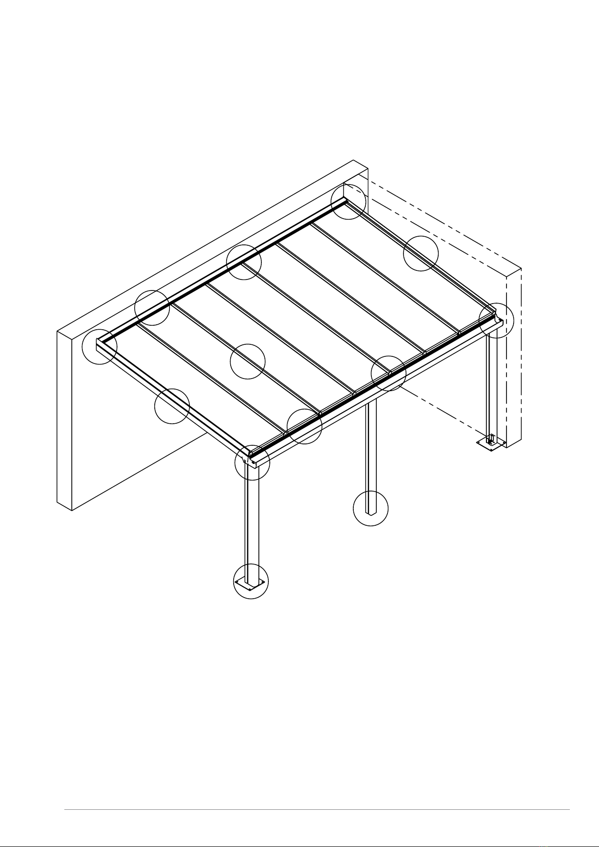
Overview of the drawing of the conservatory roof
without thermal bridge
A10 - A11: Posts, page 22-23 / 44
A20 - A23: Gutters, page 24-28 / 41
A30 - A33: Wall profiles, page 29 / 32-33 / 40
A40 - A42: Supports and side supports, page 30-33 / 36-39
E_MH_Installation_instructions_Skylux_Climax 20/11/2020
20/88
B10
B11
B20
B21
B22
B23
B40
B41
B42
B30
B31
B32
B33
Overview of the drawing of the conservatory roof
with thermal bridge
B10 - B11: Posts, page 43-44 / 67
B20 - B23: Gutters, page 45-48 / 65-67
B30 - B33: Wall profiles, page 50 / 55 / 65
B40 - B42: Supports and side supports, page 51-55 / 58-64
Table of contents
Other SKYLUX Tent manuals


Popular Tent manuals by other brands


Sunjoy
Sunjoy D-GZ850PST Assembly instructions

ShelterLogic
ShelterLogic 58432 Assembly & instruction manual

K&H
K&H Thermo Tent Assembly & care instructions

Inventini
Inventini Pascal user manual

Outdoor Revolution
Outdoor Revolution Eclipse Pro Annexe Instructions & care manual

Toptec
Toptec FUTURE TRAC Gable-End Assembly instructions