SKYLUX Climaglide User manual
CANOPY
Climaglide®
Mounting instructions carrier system - 10 mm
EN
Art.N° 80574

E_MH_Mounting_instructions_Skylux_Climaglide_10mm_carrier_system 10/09/2021
2/16
Safety
Take the necessary and required safety precautions, such as safety nets and lifelines when installing from the
outside, safety goggles, gloves, hard hat, etc.
Do not step on the glass.
Falling from height
• When using ladders to go on the roof:
- Ladder in good condition?
- Set up correctly at an angle of 75°?
- Secured below and on top against moving?
- Don’t take heavy material with you on the ladder (3-point contact rule)! If possible,
use a crane to lift the material.
• If you are going on the roof, make sure there is a walking surface that is wide enough and that
supports on the beams of the lower structure.
•When using an aerial work platform: always wear and secure your harness (mandatory)! Leaving
the cage is forbidden.
• Never walk backwards on a roof, always walk forwards.
• Make sure there’s enough light in the working zone.
Low-hanging obstacles and falling loads
• Forbidden to walk under or within a radius of 1 m of a hanging or lifted load.
• Demarcate the danger zone below the zone where there is a risk of material falling down
during the installation of the veranda.
• It’s prohibited to enter these danger zones during construction.
Crushing hazard
• All working tools are in good condition, provided with a valid CE label and all necessary safety
regulations. These cannot be removed.
• People who use these working tools are educated for this purpose. Protections are always
present on all working tools. They are in good condition and need to be set correctly.
Tripping/falling
•Safety is key and it begins with order and tidiness. Clean everything immediately, leave nothing
lying around.
• Trash needs to be sorted.
• Be cautious with electric cables (danger of tripping/falling). Never walk backwards!
• Make sure there’s enough light in the working zone.

10/09/2021 3/16
E_MH_Mounting_instructions_Skylux_Climaglide_10mm_carrier_system
Sharp objects
• Make sure your fingers/hands are not pinched and watch out for cuts while handling veranda
parts.
• Be careful where you put your hands during the installation.
• Wearing cut-resistant gloves is mandatory.
Ergonomics
• Always lift loads correctly: bend your knees, move your feet instead of forcing your spine, lift
as close to your body as possible.
• Parts of more than 25 kg must be lifted with at least 2 persons.
Personal protective equipment
• Work clothes, safety shoes and helmet are mandatory for everyone.
• Lifeline and harness are mandatory if the edge is not secured enough or if there are no safety nets below the
veranda roof. They are also necessary when using an aerial working platform.
• Use gloves when handling veranda parts.
• Safety glasses and hearing protection are mandatory when using saws / grinders.
Always perform a Last Minute Risc Analysis!
If in doubt: STOP! Do not take unnecessary risks. Ask your supervisor if needed.

E_MH_Mounting_instructions_Skylux_Climaglide_10mm_carrier_system 10/09/2021
4/16
SAFETY p. 2
OVERVIEW PROFILES AND PARTS p. 5
DRAWING p. 6
USE AND VERSIONS p. 7
GENERAL INSTALLATION TIPS p. 8
MEASURING YOUR GLASS SLIDING PARTITION p. 9
GLASS PLATES SIZES p. 10
SPECIFIC INSTALLATION TIPS p. 11 - 16
UPPER RAIL p. 11
SIDE PROFILE WITH SLIDING LOCK p. 12
SIDE PROFILES p. 12
BOTTOM RAIL p. 13
SLIDING ELEMENTS p. 14 - 15
FINISH p. 16
Contents
10/09/2021 5/16
E_MH_Mounting_instructions_Skylux_Climaglide_10mm_carrier_system
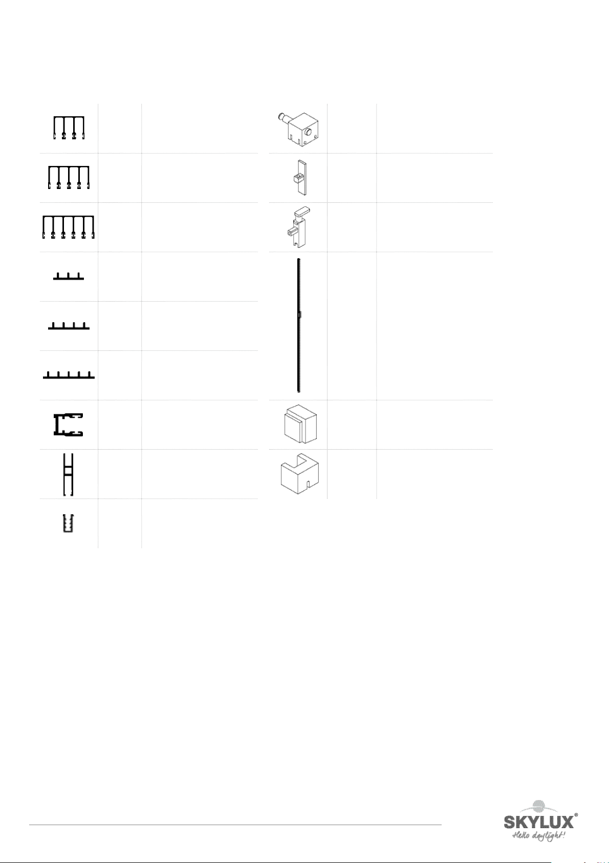
Overview profiles and parts
CGT310 Upper rail for 3 glass
panels
CGT410 Upper rail for 4 glass
panels
CGT510 Upper rail for 5 glass
panels
CGB3 Bottom rail for 3 glass
panels
CGB4 Bottom rail for 4 glass
panels
CGB5 Bottom rail for 5 glass
panels
CGL10 Side profile
CGPL10 Carrier profile
VRCG08 Seal for glass
CGBL Latch block
CGPLS10 End piece
CGPLL10 Lock
CGSHS Side profile with sliding
lock
CGCAL10U Upper mounting block
CGCAL10D Lower mounting block
E_MH_Mounting_instructions_Skylux_Climaglide_10mm_carrier_system 10/09/2021
6/16
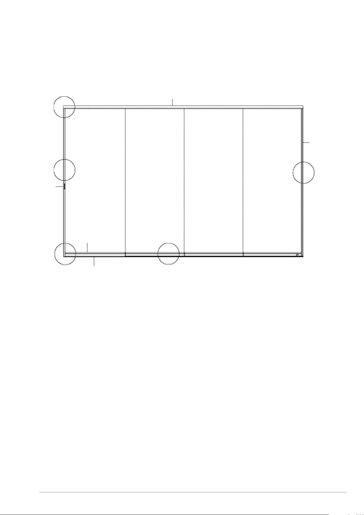
Drawing
B1
B4
B5
CGSH
sliding lock
CGT Upper rail
CGL10
side
profile
CGPL
carrier
profile
CGB bottom rail
B3
B1 = Upper rail (page 11)
B2 = Side profile with sliding lock (page 12)
B3 = Side profile (page 12)
B4 = Bottom rail (page 13)
B5 = Sliding element (page 14 – 15)
B2

10/09/2021 7/16
E_MH_Mounting_instructions_Skylux_Climaglide_10mm_carrier_system
Use and versions
Climaglide is a glass sliding partition for single glazing. This system can be locked on the inside, and provides some
protection against wind and rain. The sliding elements can be slid open to 1 or 2 sides, creating a large opening.
Climaglide is suitable for closing a non-thermal break conservatory roof such as Climax Panorama, Climalux and
Climalite.
The lower rail (CGB) has 3,4 or 5 tracks (X), is fully pre-drilled and supplied on a custom basis.
A glass sliding partition consists of several sliding elements (YY). The left and right side are determined based on
an inside position.
With a single system, the sliding elements can be parked either to the left (L) or to the right (R).
With a double system, half the sliding elements are set to the left, half to the right. The bottom rail is pre-drilled
twice beneath the track at the inside. This allows you to lock the system from the inside.
The glazing is provided by the customer/fitter in toughened (tempered) glass with a thickness (D) of 10 mm.
The version of your Climaglide glass sliding partition is determined by a code CG XYY L/R D:
Example:
CG 303 L 10 is a Climaglide glass sliding partition with 3 tracks and 3 sliding elements that open to the left (seen
from the inside out). It is equipped with a glass thickness of 10 mm.
CG 408 LR 10 is Cllimaglide glass sliding partition with 4 tracks and 8 sliding elements that partly to the right. It is
equipped with a glass thickness of 10 mm.
OUTSIDE
INSIDE
park side
CGB lower railCGSH
sliding lock
CGL10
side profile

E_MH_Mounting_instructions_Skylux_Climaglide_10mm_carrier_system 10/09/2021
8/16
General installation tips
Please read this manual carefully.
Installation must be carried out by people with sucient technical knowledge and experience of constructions.
The fitter must take the necessary safety precautions during installation, such as the use of scaolding and
personal protective equipment (safety shoes, hard hat, gloves, safety goggles, etc.) in order to work in safe
conditions. During construction, adequate precautions should be taken to ensure the stability of the unfinished
construction.
Fixing materials
The fixing materials required are chosen by you depending on the base. The screws and plugs for screwing the
profiles into the sill, the stanchions or the gutter profiles are not included. Use custom stainless steel countersunk
screws. Make sure the base and walls to which the unit is to be anchored are suciently strong. The fitter must
personally decide which fixing materials are suitable for the load and the base to which the unit is to be secured. In
case of doubt, we recommend that you contact your fixing materials supplier or a specialized engineering oce.
Lower rail
We recommend not to install the lower rail on the inner floor, but 2 mm lower.
If you install the rail more than 2 mm lower, please note that you will need to adjust the glass height.
In any case, always make sure that the bottom rail does not lean to the inside.
Skylux is not responsible for installation and for the fixing materials used.
Conditions and warranty
The warranty becomes invalid if the installation instructions below are not followed. Failure to follow these
instructions and/or the use of other parts may adversely aect the safety and life of the product. Deviations are
not permitted without the written permission of the manufacturer. Our installation manual is based on our latest
knowledge and technology status. We cannot be held liable for any incomplete information. Always check whether
our product is suitable for your use.
Since our product is processed and assembled outside of our supervision, any damage cannot be attributed to
Skylux. The fitter must bear in mind the specified dimensions of the glazing and the wind load in accordance with
applicable standards.
The manufacturer reserves the right to make technical changes without prior verbal or written notice. Skylux
reserves the right to amend this manual without prior notice. Changes in the installation instructions or to the
product carry no right to compensation or exchange of parts.
The most recent version of this manual can be consulted at any time at www.skylux.be.

10/09/2021 9/16
E_MH_Mounting_instructions_Skylux_Climaglide_10mm_carrier_system
Measuring your Climaglide glass sliding partition
Make sure the opening is perfectly square. The sill into which the lower rail is screwed must be perfectly level to
allow the sliding partition system to work properly. If the deflection of the upper profile (gutter) is more than 20
mm, the glass sliding partition cannot be installed. Bear in mind that the lower and upper rails are X times 20 mm
wide. A system with 3 tracks is therefore 60 mm wide. The stanchion on the parking side against which the glass
sliding partition is installed must have at least the same depth.
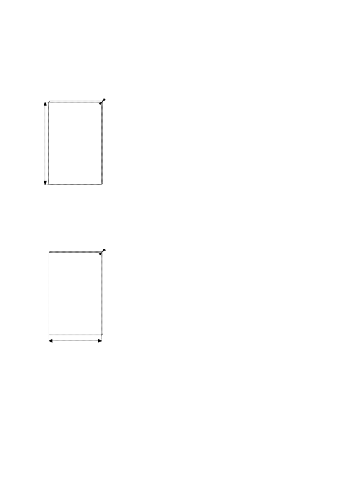
Determining the dimensions
Measure the width (Bp) between the posts.
Measure the height (Hg) from sill to gutter and check whether this corresponds to the sliding partition ordered.
The height (Hg) in the middle of the opening and at the side may dier by a maximum of 20 mm. Bear in mind that
the deflection of the gutter may be greater when loaded with snow. The maximum height Hg is 3000 mm. The
maximum weight of the glass is 80 kg.
The package delivered with the profiles and accessories is prepared with the greatest care in accordance with the
dimensions provided. First check that you have received all the parts.
post
gutter or gutter rafter
post
E_MH_Mounting_instructions_Skylux_Climaglide_10mm_carrier_system 10/09/2021
10/16
Dimensions of the glass plates
The height of the glass plate is: Hg – 85 mm.
The glass plates are distributed evenly across the width.
The width of the glass plate is:
- For a single system: (Bp-31,6+31*(X-1))/X-2,5
- For a double system: =(Bp-31,6-7+31*(X-2))/X-2,5
The glass dimensions have to be calculated. The maximum weight of the glass is 80 kg.
(where X is the number of panels)
Below is a calculation example to clarify this.
Given:
A single system CG 303 L 10 with a total width Bp of 2975 mm and an Hg of 2150 mm This glass sliding partition
has 3 panels (X) and 3 tracks
Calculating the height of the glass plates:
2150 – 85 = 2065 mm
Calculating the width per glass plate: (2975 -31,6+31*(3-1))/3-2,5= (2975 - 31,6+31*2)/3 – 2,5 = (3005,4)/3 – 2,5 =
1001,8-2,5 = 999,3 mm = 999 mm.
For this glass sliding partition, 3 glass plates of 997 x 2065 mm must be ordered in tempered glass of 10 mm, the
side edges of which must be ground.
10 mm
10 mm

10/09/2021 11/16
E_MH_Mounting_instructions_Skylux_Climaglide_10mm_carrier_system
Specific installation tips
Upper rail (CGT)
Check whether the upper profile can be anchored without perforating the gutter itself. As far as possible, it must
therefore be possible to anchor the profile in the rearmost part of the gutter profile.
Pre-drill upper profile with Ø 5-6 mm with a gap of approximately 70 cm and 4 cm from the ends. Give each hole
a chamfer so that the screw head is sunk.
Use countersunk screws to secure the profile (not supplied).
In the case of the GX gutter (Climalux), always do this in the first slot.
In the case of a GL gutter (Climalite), always do this in the second slot.
In the case of a GDG gutter (Climax Panorama), do this staggered in the first and third slots.
In the case of a GXLX gutter (Climalux Horizon), always do this in the second slot.
CGT310 CGT410 CGT510
Climalux
CGT + GX
Climalite
CGT + GL
Climax Panorama
CGT + GDG
Climalux Horizon
CGT + GXLX

E_MH_Mounting_instructions_Skylux_Climaglide_10mm_carrier_system 10/09/2021
12/16
Bottom rail (CGB)
The single system with sliding lock only has drainage holes.
The double system has 2 holes in the bottom rail to lock the sliding elements. These holes are positioned in the
central inside part of the bottom rail.
Make sure the horizontally drilled drainage holes are pointing outwards and the locking holes at the end match.
See drawing below.
Single system – with sliding lock
Double system with 6,8,10 glass
Pre-drill the lower rail with Ø 6 mm to 4 cm from the ends and also with a spacing of approximately 70 cm in the
indication lines between the outermost tracks. Give each hole a chamfer so that the screw head is sunk. Then
screw the profile onto the base with suitable screws and plugs. Provide a small water barrier with silicone at 15 mm
from the inner edge between the lower rail and the surface. Make sure the lower rail lies perfectly beneath the
upper rail and is level. If necessary, shims must be used to align the lower rail horizontally.
CGB3 CGB4 CGB5
water drainage
OUTSIDE
INSIDE
water drainage water drainage
water drainage
OUTSIDE
INSIDE
water drainage water drainage
hole for lock CGPLL10 hole for lock CGPLL10

10/09/2021 13/16
E_MH_Mounting_instructions_Skylux_Climaglide_10mm_carrier_system
Side profile (CGL10) + side profile with sliding lock (CGSHS)
Needs to be sawn to the precise length on the construction site. Make sure the milled-out opening is facing
downwards. For centering side profile (CGL10) use upper and down mounting block (CGCAL10U, CGCAL10D).
First position the side profile on the parking side and centered above the outermost track. Then screw the profile
to the stanchion. Use short screws for this, so that the water discharge pipe is not pierced. Screws should have a
chamfered head (max. diameter of the head is 10,4 mm). Do the same against the other stanchion, but centrally
above the innermost track.
CGCAL10U
CGCAL10D
side profile with sliding lock
CGHS
side profile
CGHL10
lower rail
CGB
park side
E_MH_Mounting_instructions_Skylux_Climaglide_10mm_carrier_system 10/09/2021
14/16
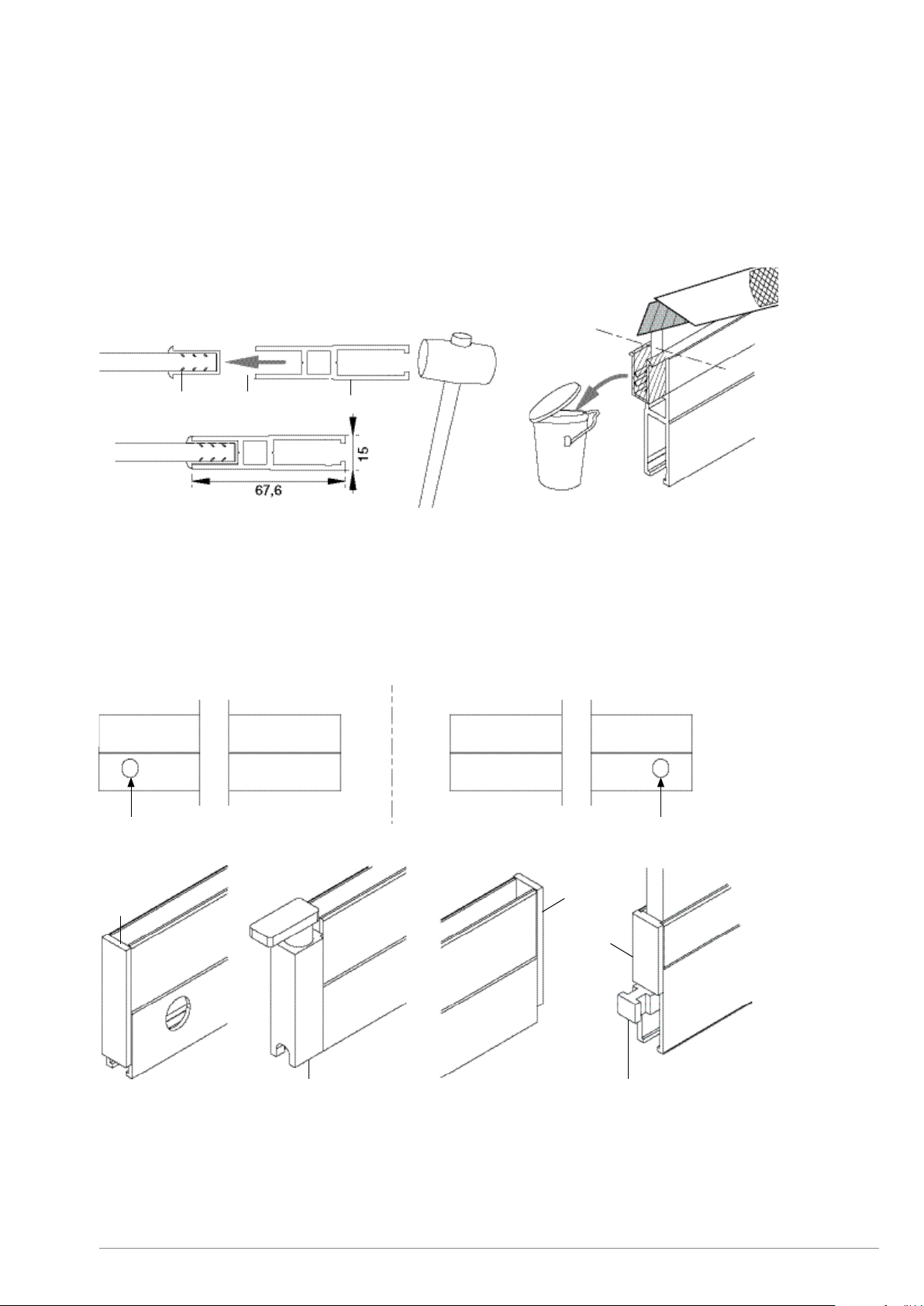
Sliding elements (CGPL)
The carrier profiles are custom-made and fitted with wheel guidance and locks. In the single system with one lock,
there is one carrier profile fitted with a lock opening. It’s used for the sliding element on the parking side. There is
also another carrier profile with locking side which goes to side profile with sliding lock.
Installing the sliding elements
Lay the glass plate horizontally on 2 trestles. Provide protection against scratches. Take the rubber strip and cut
it 1 cm longer than the width of the glass. Position this on the face side of the glass plate. Take the carrier profile
and remove at least one end piece or lock piece. Coat the carrier profile on the inside with a detergent solution.
Position the top of the carrier profile over the rubber and make sure the side of the carrier profile is aligned with
the side of the glass plate. First, push the carrier profile manually on the glass as far as possible. Tap the carrier
profile into the glass plate with a rubber hammer (we recommend 700 gr) until only the edge of the rubber
remains visible. Measure the squareness of the glass against the profile with a try square. The surplus rubber
protruding at the sides must be cut o. Remount the end pieces and/or lock pieces.
In case of single system, there are end pieces CGPLS10 on each carrier profile on both sides, except on the carrier
profile which is locked by the sliding lock – this profile has a shorter end piece (CGPLSS10) on the locking side and
a standard end piece.
In case of double system, there are two locks (CGPLL10), one on both carrier profiles. On the opposite sides and
other carrier profiles, there are end pieces (CGPLS10). On the rest of carrier profiles, there are two end pieces
(CGPLS10).
glass rubber carrier profile
lock opening left lock opening right
CGPLS10
CGPLL10
CGPLS10
carrier – locking side
CGPLSS10
10/09/2021 15/16
E_MH_Mounting_instructions_Skylux_Climaglide_10mm_carrier_system
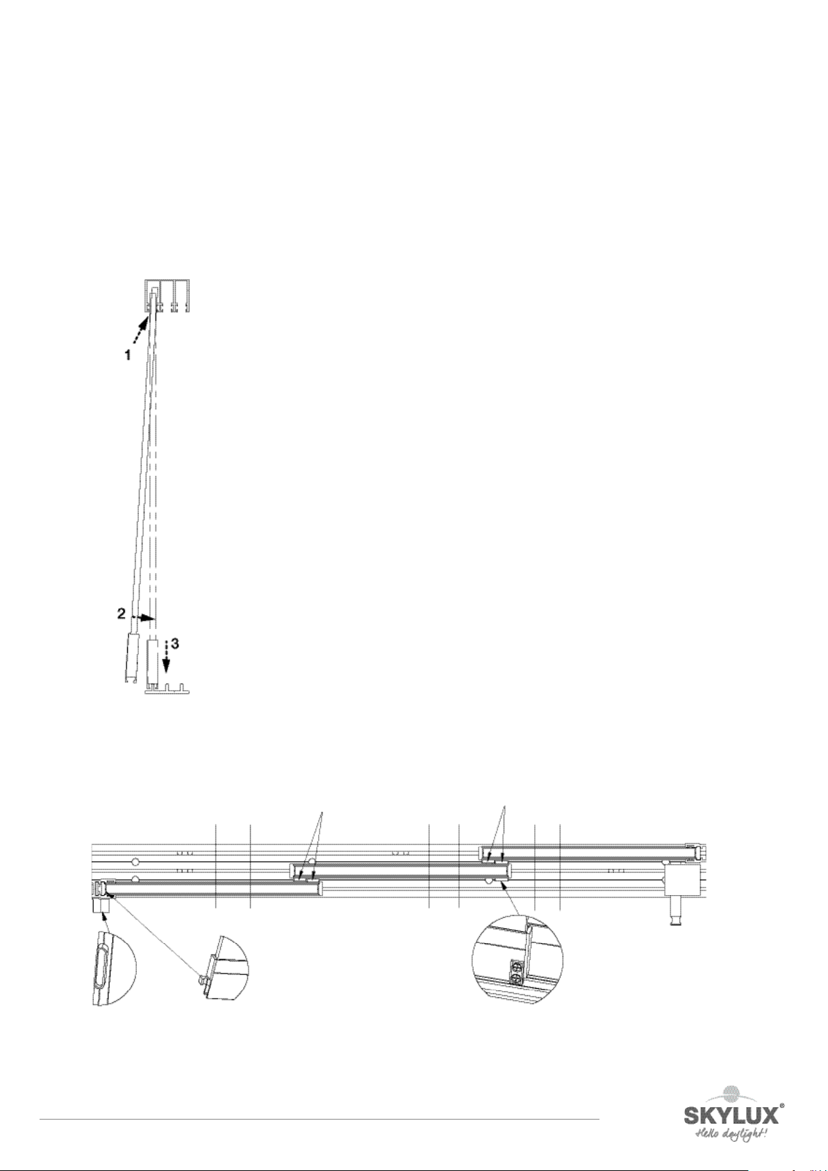
Install the first element with lock opening pointing inside on the parking side on the outermost track. Tip the
sliding element up in the outermost guide of the upper rail. Tilt the element until it is vertical and let it drop until
the wheel guide fits onto the outermost track. The first sliding element is now positioned. Check if the sliding
element stands perfectly straight and horizontal. If not, the rail and the upper track must be aligned. Repeat this
procedure for all sliding elements, each time on the next track. Make sure the lock is pointing towards the parking
side. Now slide each element carefully over the entire length of the opening to check that there is no catching on
the screws in the upper rail.
collecting pieces collecting pieces
collecting piece
park side
carriage - locking sidesliding lock

E_MH_Mounting_instructions_Skylux_Climaglide_10mm_carrier_system 10/09/2021
CLIMAGLIDE IS A REGISTERED BRAND OF SKYLUX
SPINNERIJSTRAAT 100 B8530 STASEGEM
T +32 056 20 00 00 F +32 056 21 95 99
INFO@SKYLUX.BE
WWW.SKYLUX.BE
ONLY USE ORIGINAL PARTS DELIVERED BY SKYLUX. EVERY GUARANTEE IS CANCELLED IF NONORIGINAL PARTS ARE USED.
THESE GUIDELINES ONLY HAVE AN ADVISORY CHARACTER. ASSEMBLY FALLS UNDER THE ENTIRE RESPONSIBILITY OF THE CUSTOMER.
The finish
Install the locking block on the parking side on the lower rail with a hex key. Adjust the position so that the lock
enters the opening of the carrier profile.
Also test the locking positions of the other sliding elements.
For the seal against rainwater, we recommend finishing the lower rail on the inside with silicone.
You can additionally opt for round handles. We oer two dierent types:
- to be glued to the glass panels (glass glue can be ordered separately)
- to screw into the glass panels (predrill the glass panels with Ø 60)
To prevent someone walking into the transparent sliding elements, we recommend axing a self-adhesive opaque
strip to the glass at eye level.
If you have ordered the sealing brushes, they can now be sawn to length and be fixed on the glass with a suitable
glue (TEC7 transparent or simular).
Table of contents
Other SKYLUX Tent manuals


