Skytron SS2201-J2 User manual

OWNER'S MANUAL
WARMING
CABINETS MODELS SS2201-J2
THROUGH SS2207-J2
TEC-F-0007 REV8
9/13


Page 1
J2 WARMING CAB. OWNER'S • REV8
TABLE OF CONTENTS
TITLE PAGE
Although current at the time of publication, SKYTRON’S policy of continuous development makes this
manual subject to change without notice.
PRODUCT SAFETY LABELS .................................................................................................................2
SPECIAL USER ATTENTION..................................................................................................................4
SPECIFICATION DRAWINGS.................................................................................................................5
SECTION I INTRODUCTION..................................................................................................................8
SECTION II OPERATION.......................................................................................................................10
SECTION III MAINTENANCE & REPAIR...............................................................................................13
SECTION IV REPLACEMENT PARTS...................................................................................................20
WIRING DIAGRAM ................................................................................................................................22
TRANSPORT AND STORAGE REQUIREMENTS
• Ambient temperature range: -40° to +159°F (-40° to +70°C)
• Relative humidity range of 10% to 100% including condensation.
• Atmospheric pressure range of 50KPa to 106KPa
ELECTRICAL INFORMATION
SS2201-J2(G) SS2205-J2(G) SS2207-J2(G)
Electrical 120V, 50/60Hz,1PH 120V, 50/60Hz,1PH 120V, 50/60Hz,1PH
Amp Rating 2.0 Amps 6.5 Amps 8.8 Amps
Power Usage 240 Watts 720 Watts 1056 Watts
This manual has four main sections, each developed for a certain reader.
1. General Description: For all readers
2. Operation: For staff who use the warming cabinets
3. Service: For authorized SKYTRON trained personnel
4. Installation Instructions: For contractors and authorized SKYTRON service personnel who install
warming cabinets. (Refer to section 1-2.)
Model Identication
The data tag can be found on each warmer inside the uppermost compartment on the left hand side closest
to the door. Record your Model Number and Serial Number below. For prompt service, please have your
model and serial number ready when contacting SKYTRON for assistance.
Model #_______________________________
Serial #_______________________________

Page 2
J2 WARMING CAB. OWNER'S • REV8
Appliance must be located
a minimum of 6 feet
from patient.
1-ALWAYS DISCONNECT POWER WHEN SERVICING THIS DEVICE TO ELIMINATE RISK OF ELECTRIC SHOCK!
2-Refer to the Operating Manual provided prior to using this device, or anytime you have a question about safe operation.
3-Refer to the General Set-up Instructions provided by the Manufacturer when installing this device.
4-Employ safe blanket loading practices and ensure that no blankets are in contact with the rear surface of the warmer.
5-Do not stack blankets closer than 4” from fan inlet.
6-Do not allow stacked blankets to extend past front lip of shelves to ensure airflow within the cabinet is not restricted.
7-Care should always be taken to ensure the door is closed and latched upon loading or retrieving contents from the cabinet.
8-Use warm water and a mild liquid detergent to remove finger prints and light soil from the stainless steel surfaces.
BLANKET WARMER-SAFE OPERATING INSTRUCTIONS
MODEL
CYCLES
MAX. KWS.
PHASE
SER. NO.
VOLTAGE
MAX. AMPS
EQUIP. NO.
1-800-759-8766
Manufactured by JAMESTOWN METAL PRODUCTS, INC.
12
3
456
9
8
7
PRODUCT SAFETY LABELS
F2-012-81
F2-012-82

Page 3
J2 WARMING CAB. OWNER'S • REV8
LABEL LOCATIONS
Technical Data
•Dimensions-Inches (millimeter)
SS2201-
J2(G)
SS2205-
J2(G)
SS2207-
J2(G)
Exterior
Width 30(762) 30(762) 30(762)
Height 26(660) 74(1880) 74(1880)
Depth 26(660) 26(660) 26(660)
Interior Upper
Width 27(686) 27(686) 27(686)
Height 15(381) 59(1499) 15(381)
Depth 19(483) 19(483) 19(483)
Lower
Width 27(686)
Height 35¼(895)
Depth 19(483)
•Capacity
Cubic capacity (Liter capacity)
SS2201-
J2(G)
SS2205-
J2(G)
SS2207-
J2(G)
Total
Volume
4.37 ft3
(124)
17.5 ft3
(496)
15.72 ft3
(445)
Upper
Chamber
N/A N/A 4.37 ft3
(124 L)
Lower
Chamber
N/A N/A 11.35 ft3
(321)
•Weight
SS2201-
J2(G)
SS2205-
J2(G)
SS2207-
J2(G)
Weight 179 340 404

Page 4
J2 WARMING CAB. OWNER'S • REV8
WARNING
Disconnect (power) supply before
servicing.
WARNING
Explosion Hazard
Donotuseinthepresenceofammable
Anesthetics.
NOTE
This warmer should not be left
unattended
for periods greater than 24
hours. In case of extended absences
disconnect warmer from its power
source.
NOTE
To promote a self closing door swing,
the front door hinge corner leveling foot
should be slightly higher than the others.
NOTE
To insure proper heat distribution, allow
airowspaceonthetopanddoorside
of blankets. DO NOT BLOCKAIR VENT.
NOTE
Avoidusingammablecabinetcleaning
agents, as well as blanket cleaning
agents that cause fabric to become
brittle over time.
Knowledge of proper procedures is essential to the
safe operation of this equipment.
The following precautions should be reviewed
by all personnel prior to operating this
equipment.
WARNING
Indicates a possibility of personal injury.
CAUTION
Indicates a possibility of damage to
equipment.
NOTE
Indicates important facts or helpful hints.
WARNING
Patient Burn Hazard
Temperature of cabinet contents may
differ from display temperature.
WARNING
The temperature of liquids in this cabinet
may not be suitable for certain patient
applications.
Always check the temperature of
contents before using.
SPECIAL USER ATTENTION

Page 5
J2 WARMING CAB. OWNER'S • REV8
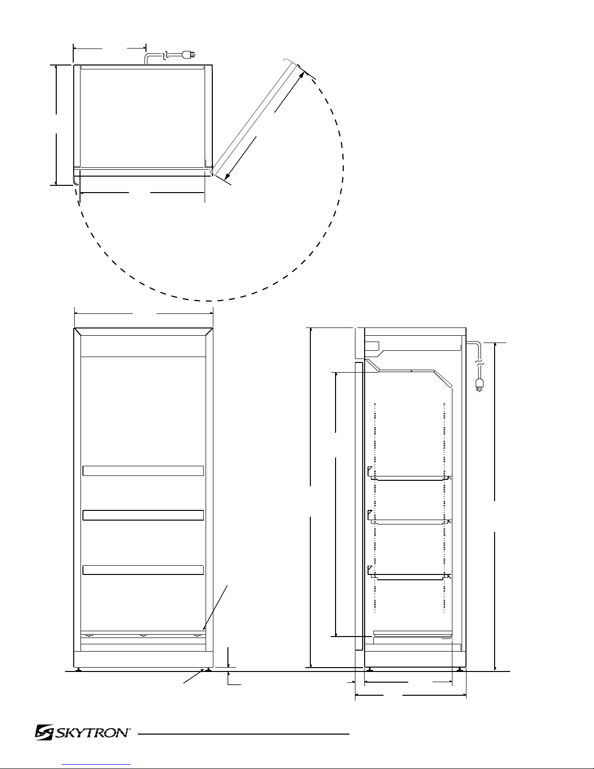
30"
762mm
18½"
470mm
6½"
165mm
24"
610mm
2"
50mm
26"
660mm 15"
381mm
19"
483mm
HINGES ARE
REVERSIBLE FOR
OPPOSITE DOOR
SWING
FRONT SIDE
LEVELING FEET (4) ½"
13mm
27"
686mm
26"
660mm
TOP 29¼"
743mm
15"
380mm
23½"
597mm
235°
DOOR SWING
MODELS
SS2201-J2
SS2201-J2G
Page 6
J2 WARMING CAB. OWNER'S • REV8
27"
686mm
26"
660mm
TOP 29¼"
743mm
15"
380mm
235°
DOOR SWING
73½"
1867mm
HINGES ARE
REVERSIBLE FOR
OPPOSITE DOOR
SWING
FRONT SIDE
LEVELING FEET (4)
59"
1499mm
½"
13mm
2"
50mm 24"
610mm
19"
483mm
30"
762mm
71½"
1816mm
MODELS
SS2205-J2
SS2205-J2G

Page 7
J2 WARMING CAB. OWNER'S • REV8
16¼"
413mm
44"
1118mm
15"
381mm
35¼"
895mm
LEVELING FEET (4)
FRONT SIDE
6½"
165mm
HINGES ARE
REVERSIBLE FOR
OPPOSITE DOOR
SWING
73½"
1867mm
½"
13mm
2"
50mm 24"
607mm
19"
483mm
30"
762mm
27"
686mm
26"
660mm
TOP 29¼"
743mm
15"
380mm
235°
DOOR SWING
71½"
1816mm
MODELS
SS2207-J2
SS2207-J2G

Page 8
J2 WARMING CAB. OWNER'S • REV8
users are in-serviced with the use, limitations
and hazards. No other use is authorized or
recommended.
d. Construction
The body of the warming cabinet is double walled
stainless steel construction with insulation for
increased heating efciency. Doors are made
of double paned stainless steel or double paned
tempered glass framed with stainless steel.
e. Servicing
All control components are located in the control
compartment at the top of the warmer and serviced
by removal of the front panel. Servicing of circulation
fans, heating elements and manual temperature
overloads are accessed through the interior of
each heating chamber with the door(s) open only
by SKYTRON Authorized Service Technicians.
f. Features
• Illuminated power on/off switch
• Insulated body and door(s)
• Silicone door gasket(s)
• Independent digital thermostatic controls and
displays
• Reversible door swing
• Front access serviceability
• Leveling feet
• Exterior/interior stainless steel construction
• 8’ power cord
• Adjustable shelves for SS2205 and SS2207
models
• Temperature range of 90° to 160°
g. Installation
SS2201-J2(G) – counter, under counter, or cart
SS2205-J2(G) & SS2207-J2(G) – freestanding
h. Options
• Glass doors (G) on end of model number
• Casters kits
• SS2201-J2(G) – F2-012-58
• SS2205-J2(G) or SS2207-J2(G)
– F1-010-102
• Warmer cart (F1-020-23) for counter top
models
• Warmer stand (F1-020-23-NC) for
counter top models
SECTION I INTRODUCTION
1-1. General
SKYTRON Stainless Blanket and Solution Warming
Cabinets are designed to provide heated storage of
blankets, sterile water and saline solutions used in
the care of patients in surgery, recovery, OB/GYN,
ICU, ER and trauma areas. SKYTRON Model
SS2201-J2(G) offers a compact size with one
warming compartment. Model SS2205-J2(G) offers
a full size cabinet with one warming compartment.
Model SS2207-J2(G) provides upper and lower
compartments.
a. Controls
The controls for each compartment are mounted
in the top section of the warmer and labeled Upper
Chamber and Lower Chamber, with a circuit breaker
providing power to each control.
Each compartment controller:
• Controls on/off of the compartment
• Set point of temperature 90° to 160°
• Temperature display in Fahrenheit
Digital read out provides:
• Chamber temperature
• Temperature set point
• Heating active
• Over heat (alarm)
An audible and visual AL alarm
indicates an overheat condition.
• Loss of power
b. Performance
Heated air is circulated over the contents by fan(s)
in a convection function providing an even heat
distribution. Each compartment is designed to
hold a quantity of blankets or solutions. Once a
set temperature is selected and obtained it will be
controlled throughout within 10° of the selected
temperature. From a cold start, each compartment's
loaded contents will be evenly heated to set point
within 8 to 12 hours. In the event of power loss the
warmer will resume normal function once power
is restored.
c. Usage
This device is intended for warming 100% cotton
blankets ONLY and non-ammable solutions in
commercial establishments where all operators/
Page 9
J2 WARMING CAB. OWNER'S • REV8
h. Clean all exterior and interior surfaces of
the warming cabinet as needed with a damp
towel and a mild non-abrasive detergent. Rub
surfaces in a back and forth motion in the
direction of the grain, do not wipe in a circular
motion or perpendicular to the grain.
i. Plug the power cord into a properly grounded
120V electrical outlet.
1-3. Service / Principles of Operation
This equipment contains no user serviceable parts.
To avoid injury, refer all repairs to SKYTRON trained
service personnel.
Model SS2201-J2(G) is a single compartment 1/3
size, SS2205-J2(G) is a single compartment full size,
and model SS2207-J2(G) is a dual compartment full
size warmer. Each compartment has independently
controlled temperature regulation by a thermostatic
control unit and independent thermal protection
cut off.
Each warming compartment is designed to circulate
air from the top of the chamber over a heating
source, which cycles on and off by means of a
sensor to maintain set temperature, and back out at
the bottom of the chamber. This process produces
a convection type of heating system.
Dual compartment warmers have an air barrier
between the upper and lower compartments
restricting heat migration to the upper chamber
and affecting the temperature setting.
1-2. Installation / Uncrating
Move the warming cabinet to the location of
installation prior to uncrating.
a. Remove metal banding securing the cabinet
to the pallet.
b. Remove all packing materials covering the
warmer.
c. Remove the warmer from the pallet and position
in desired location.
d. Open the door(s) and remove the shipping
brackets and replace the screws in the body
of the cabinet.
e. Remove the shipping brackets holding the
shelves in the bottom compartment and discard.
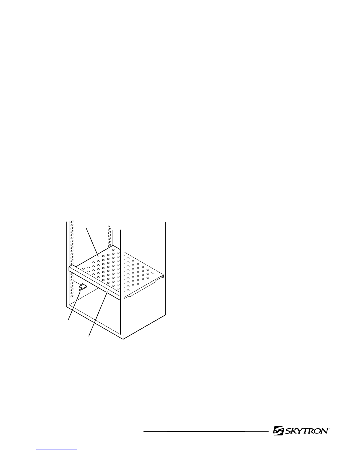
f. Install shelf supports as outlined in the Shelf
Adjustment portion of the Operation Section.
SHELF SUPPORT
(4 per shelf)
FRONT
SHELF
g. Make sure the cabinet is leveled properly
to the floor or counter top by adjusting
the leveling feet at the bottom of the
cabinet. To promote self closing door swing,
the front door hinge corner leveling foot
should be slightly higher than the others.

Page 10
J2 WARMING CAB. OWNER'S • REV8
SECTION II OPERATION
Control Layout Display Messages
ERROR CODE DESCRIPTION
ER Memory Error
-- Short-Circuit Probe Error
oo
Open Probe Error
Initial Operation
Initial power up
a. Plug the power cord into a properly grounded
120VAC electrical outlet.
b. Turn circuit breaker on the front control panel
to the ON position.
c. Turn the power switch to the ON position for
each compartment.
d. The display should illuminate with the current
chamber temperature.
Alarm Test
a. Press the SET button on the temperature
control. SP will appear on the display.
b. Press the SET button again. The present
temperature setting will appear on the display.
c. Using the Up/Down arrow buttons, set the
new set point to 110° and press SET to lock
the new value.
d. Allow stabilization of the heating chamber.
e. Repeat steps one and two above and press the
down button to 95° and press the SET button.
•Thealarmactivates
f. To silence the alarm, press the SET button and
the DOWN arrow key together.
Description of controls
Each temperature controller and power switch
operates one warming compartment.
Circuit Breaker – main power to the warming
cabinet controllers.
Power Switch – turns on/off the fan, controller and
heating functions of the selected compartment.
Display – normally shows the current interior
chamber temperature.
Up Arrow Button – used to adjust the set point of
the selected chamber.
Down Arrow Button – used to adjust the set point
of the selected chamber.
Set Button - when pressed displays the selected
warming chambers desired set point.
DISPLAY
POWER
SWITCH
CIRCUIT
BREAKER UP ARROW
BUTTON
DISPLAY SET
BUTTON
DOWN
ARROW
BUTTON

Page 11
J2 WARMING CAB. OWNER'S • REV8
Operating Instructions
Turning the warmer on
a. Make sure the power cord is plugged into a
properly grounded 120VAC electrical outlet.
b. Turn circuit breaker on the front control panel
to the ON position.
c. Turn the power switch to the ON position for
each compartment.
The display should illuminate with the current
chamber temperature.
Selecting the temperature set point
a. Press the SET button on the temperature
control. SP will appear on the display.
b. Press the SET button again. The present
temperature setting will appear on the display.
c. Using the Up/Down arrow buttons, set the new
set point to the desired temperature and press
SET to lock the new value.
d. Press SET and DOWN simultaneously to return
back to normal operation.
Note: if the set point is changed to a value 10°
below current temperature the alarm will activate.
Loading of the cabinet
Load only sterile water, saline solutions or 100%
cotton blankets, do not warm synthetic blend fabrics
or items containing plastic, rubber, or metal snaps,
studs, hooks etc. Check for proper placement of
the shelf on shelf supports prior to loading. The
blanket shelf is perforated to facilitate even heating
of blankets placed on the shelf and must be used
to hold blankets.
All loads should be allowed time to stabilize at the
set temperature; Do not raise set temperature to
increase the rate of heating:
• Solutions - Approximately 8 to 12 hours
• Blankets - Approximately 6 to 8 hours
Bottles should be loaded to allow for a minimum of
one half inch from the top of the compartment and
spacing around the back and sides one quarter inch
andnotprotrudepastthefrontedgeoftheuidtray
in the compartment for evenly distributed heating.
Forefciencypurposesbaggedsolutionsshould
be placed on shelves, stacking of uid bags
increases the heating time required to achieve set
temperature.
Blankets must be folded and stacked to allow a
two to three inch open space between the top of
the compartment or shelf, on each side and rear
of the stacked blankets, nor protrude past the front
edge of the shelf. Following the above guidelines
improves the efciency of heating the contents
thoroughly.
Rotatewarmedcontentsonarstinrstoutbasis
failure to do so may present cold or discolored
contents.
Temperature settings for uids vary depending
on use or manufacturer. Always refer to AORN
guidelines and manufacturer’s recommendations
for proper temperature settings.
Flammable agents in the warming cabinet can
causeanexplosionorre.Donotloadthewarming
cabinetwithanyitemthatcouldintroduceammable
agents into the cabinet atmosphere.
In case of power failure the unit will resume normal
operationwhenpowerisrestored.Followtheuid
manufacturer’s guidelines for solutions that have
cooled or been removed from heated storage but
not used.

Page 12
J2 WARMING CAB. OWNER'S • REV8
Unloading of the cabinet
Internal surfaces of the warmer are hot. Avoid
contact when loading and unloading the warming
cabinet.
CAUTION
Glass may shatter when cooled
suddenly, solution bag and bottles may
burst when picked up.
CAUTION
Temperatures over 110° may burn when
exposed for extended periods of time.
Skytron recommends the use of personal protective
equipment while loading and unloading of contents.
Turning the warmer off
a. Move the on/off rocker switch(es) to the OFF
position of the compartment to shut down.
b. Moving the circuit breaker switch to the OFF
position will shut down the entire warmer
Overheat Alarm (A1) Condition
When the chamber temperature exceed the set
point by 8° or more the display will read A1 and
the audible alarm is triggered.
a. To silence the audible alarm press and hold the
SET and DOWN buttons together until silenced.
b. Turn off the warmer chamber and unload the
contents and reload following the loading
guidelines previously outlined.
c. Turn on the chamber and monitor for
performance. If the chamber overheats into an
alarm (A1) condition turn off the chamber and
contact your local authorized service personnel
for troubleshooting.
If lowering the set temperature of the chamber
more than 10° of current internal temperature the
alarm will activate. Follow the procedure above
to silence the alarm.
Shelf Adjustment
a. Turn off the power to the heating chamber
where the adjustment is needed.
b. Allow the chamber to cool and unload the
contents.
c. Remove the shelf
d. Determine the new position of the shelf
e. To remove the shelf supports pull the bottom of
the support toward the interior of the chamber
to approximately a 90° angle and out toward
the center of the chamber.
f. Install the shelf support into the new location
by inserting the top of the support into the new
position and rotating down toward the bottom
of the cabinet until the bottom tab locks in.
g. Count the empty holes in the pilaster at each
of the corners to be sure that the shelf will be
level in the new position.
h. Reinstall the shelf with the raised edge toward
the front of the cabinet.
i. Align notches in bottom of the shelf with the
shelf supports.
j. Pull outward on shelf to insure it is locked
properly on the supports.
SHELF SUPPORT
(4 per shelf)
FRONT
SHELF
Page 13
J2 WARMING CAB. OWNER'S • REV8
3-1. Troubleshooting
If your unit is not operating properly, check the following before calling your authorized service agent.
Do not attempt to repair or service beyond this point. Contact SKYTRON for nearest authorized service
agent.
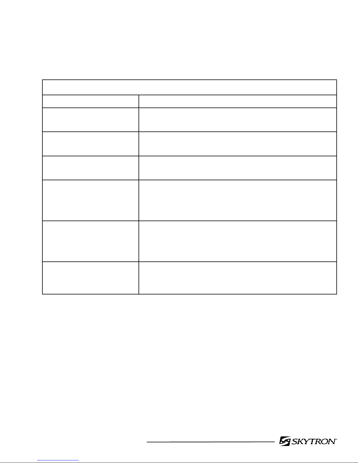
TROUBLESHOOTING GUIDE
DESCRIPTION ACTION REQUIRED
ER - Memory Error Controller Defective, Replace - Contact SKYTRON
representative
--- Short Circuit Probe Error Temperature Probe Defective, Replace - Contact SKYTRON
representative
oo
- Open Probe Error Temperature Probe Defective, Replace - Contact SKYTRON
representative
Unit Will Not Power Up • Check Outlet for Power
• Check if warmer is plugged into 120VAC outlet
• Check if circuit breaker is turned on
• Check if the power switch is turned on
Chamber does not Heat • Is the power turned on
• Is temperature set above Chamber Ambient Temperature
• Is the Circulation Fan Operational
• Is the Limit Thermostat reset
Over Temperature Alarm
"A1" is Activated
• Is the Circulating Fan Operational
• Are the Contents Loaded Properly
• Has the Chamber Set Temperature been lowered
Onlyfacilityauthorized,SKYTRONtrained&certied,maintenancepersonnelshouldfurther
troubleshoot or attempt repairs.
Troubleshooting or repairs by unauthorized personnel could result in personal injury or equipment
damage.
SECTION III MAINTENANCE & REPAIR

Page 14
J2 WARMING CAB. OWNER'S • REV8
3-2. Preventative Maintenance
a. Every 6 months - Cleaning
It is recommended to perform preventative
maintenance on the Skytron model warming
cabinets every six months or when any service is
performed.
1. Turn off the power and unplug the warmer
from the power source.
2. Using a damp cloth and mild non abrasive
detergent rub surfaces in a back and forth
motion in the direction of the grain, do not
wipe in a circular motion or perpendicular to
the grain.
• Clean all exterior surfaces
• Remove all contents and clean all shelving
• Cleanallinteriorchamberwalls,oorand
ceiling starting at the top and working down
3. Restore power to the warmer and allow
temperatures to stabilizer prior to reloading
solutions and blankets.
b. Every year - Internal Cleaning
Removal of the interior plenum panels:
1. Remove the bottom spill pan with the four
Phillips head retaining screws two in each side.
2. Remove the bottom plenum by removal of the
four Phillips head screws at the front edge.
3. Supporting the ceiling panel remove the four
Phillips head screws that hold the rear plenum
to the ceiling plenum.
4. Support the ceiling plenum and pull the rear
plenum at the bottom toward the front of the
warmer to remove.
5. Remove the ceiling plenum by disconnecting
the fan power wires.
6. Clean all exposed surfaces with a damp cloth
and mild non abrasive detergent.
7. Assemble plenum panels in the reverse order
of removal.
8. Plug the warmer in and turn the power on.
c. Yearly - Temperature Controller Calibration
1. Place an independent accurate thermometer
in the chamber and close the door.
2. Set the temperature to a setting between 90°
and 160°.
3. Allow chamber to acclimate to the selected
temperature.
4. Compare controller reading with independent
thermometer
5. Adjust controller program value P1 up or down
to correct any offset in readings. (see control
settings section)

Page 15
J2 WARMING CAB. OWNER'S • REV8
3-3. Limit Thermostat Reset
It may be necessary to reset the Limit Thermostat
of a chamber due to a malfunction or a faulty
controller. This is a safety cutout switch installed
in each plenum area that is designed to interrupt
power to the heating element if the temperature
exceeds 180° F during operation. To reset the
Limit Thermostat the following instructions should
be followed.
a. For models SS2201-J2(G), SS2205-J2(G)
and upper chamber of SS2207-J2(G):
1. Disconnect the power to the warmer by
unplugging the unit.
2. Remove the top cover from the warming
cabinet by removal of four Phillips head screws
and place to the side.
3. The Limit Thermostat is located at the rear
center of the cabinet.
4. Pressrmlyonthecenterredbuttonuntilan
audible snap is heard.
5. Replace the top cover and install the fastening
screws.
6. Plug the warmer back into a power source.
7. Monitor the warmer for normal operation.
b. For lower chamber of SS2207-J2(G):
1. Disconnect the power to the warmer by
unplugging the unit.
2. Remove the fan assembly from the ceiling
plenum by removal of four Phillips head
screws and unplug the power cord and place
to the side.
3. The Limit Thermostat is located at the rear
center of the cabinet.
4. Pressrmlyonthecenterredbuttonuntilan
audible snap is heard.
5. Replace the fan assembly and install the
fastening screws.
6. Plug the warmer back into a power source.
7. Monitor the warmer for normal operation.
3-4. Fan Replacement
Failure of a circulation fan can cause the warming
chamber to overheat and enter an alarm mode.
The following procedure should be followed to
replace the circulation fan.
1. Disconnect the power to the warmer by
unplugging the unit.
2. Remove the fan assembly from the ceiling
plenum by removal of four Phillips head
screws and unplug the power cord and place
to the side.
3. Remove the four screws that secure the fan
to the fan panel.
4. Install the new fan paying attention to the
direction of ow; there are arrow markings
onthefantoindicateow.Thefanshould
have the arrow pointing away from the fan
mounting panel (UP).
5. Replace the fan assembly and install the
fastening screws.
6. Plug the warmer back into a power source.
7. The fan should start to operate as soon as the
power is turned on to the chamber repaired.
Note: It may be necessary to reset the Limit
Thermostat if the chamber heated to a temperature
greater than 180° F.

Page 16
J2 WARMING CAB. OWNER'S • REV8
3-5. Heating Element and/or Temperature
Probe Replacement:
The Heating Element and Temperature Probe are
located in the heating plenum and positioned close
to each other. The following procedure will allow
for exchange of either or both parts.
1. Disconnect the power to the warmer by
unplugging the power cord from the 120V
outlet.
2. Removal of the interior plenum panels.
• Remove the bottom spill pan with the four
Phillips head retaining screws two in each
side.
• Remove the bottom plenum by removal of the
four Phillips head screws at the front edge.
• Supporting the ceiling panel remove the
four Phillips head screws that hold the rear
plenum to the ceiling plenum.
• Support the ceiling plenum and pull the rear
plenum at the bottom toward the front of the
warmer to remove.
• Remove the ceiling plenum by disconnecting
the fan power wires.
3. The heating element is located on the rear wall.
• Remove the electrical connections from the
element.
• Disconnect the heating element from the
mounting location.
• Install the new element and replace the
electrical connections.
• Proceed to step 5.
4. The temperature probe is located above the
heating element and held in place with a hold
down tab and secured with a Phillips head
screw.
• Loosen the Phillips head screw and slide
the probe out from under the hold down tab.
• Cut the wires off from the probe approximately
8” to 10” from the probe.
• Strip the wires back and attach the new
probe wires to the old probe.
• Secure the new probe under the hold down
tab and tighten the retaining screw.
• Remove the front control panel from the
warmer by removing the four Phillips head
screws, one on each corner.
• Pull the control panel out until all attached
components are clear of the warmer body.
• Roll the panel upward and place on top of
the warming cabinet.
• Find the Temperature probe wires previously
cut and pull the new probe wires through
the wire chase.
• Remove the old probe wires from the
controller and attach the new wires.
5. Reassemble the plenum panels.
• Assemble plenum panels in the reverse order
of removal in step 1.
• Plug the warmer in and turn the power on.
Note: It may be necessary to calibrate the probe to
the chamber by adjusting the offset in the controller,
value P1. See Preventative Maintenance Section
2 on Calibration of the temperature controller to
the chamber.

Page 17
J2 WARMING CAB. OWNER'S • REV8
15. Install the upper door and install upper hinge
pin. Follow step 14.
16. Replace the control panel using the 4 Phillips
head screws previously removed.
17. Plug the warmer back into the power source.
b. Door latch adjustment
1. Slowly close the door and adjust the height
of the keeper to provide between 1/8" to
1/16" clearance between the KEEPER and
the LATCH PAWL. Mark the location, open
the door and tighten the (2) screws. Test and
readjust as required to insure proper operation.
2. If the proper clearance cannot be achieved
with the available adjustment of the keeper
to the latch pawl, it may be necessary to add
additional washers to the bottom hinge pin of
the door. (Follow DoorAdjustment/Orientation
procedure instructions.)
3-6. Door Adjustment/Orientation
a. The following procedure can be used to change
the orientation of the door swing or to make
adjustments to the latch alignment.
1. Disconnect the power to the warmer by
unplugging the power cord from the 120v
outlet.
2. Remove the front control panel from the
warmer by removing the four Phillips head
screws, one on each corner.
3. Pull the control panel out until all attached
components are clear of the warmer body.
4. Roll the panel upward and place on top of the
warming cabinet.
5. Remove the hinge pin from the top bracket
while supporting the door.
6. Tilt the door out and lift off the lower hinge pin
and set aside.
7. For dual compartment warmers remove the
center hinge bracket while supporting the
lower door.
8. Lift the door up and set to the side.
9. Remove the lower hinge bracket and secure
to the opposite side of the warmer at the top
and remove the hinge pin from the bracket.
10. Replace the hinge pin in the original top hinge
bracket and remove from the cabinet and install
at the opposite side lower position.
11. Remove the door latch keepers and mounting
plate and secure to the opposite side of the
cabinet. Removal/Replacement of the door
Latch Pawl is recommended.
12. Rotate the door 180° and position on the
lower hinge pin.
13. Install the center hinge bracket and secure to
the cabinet if dual chamber.
14. Check for alignment of the latch keeper to
the latch pawl. Adjust the keeper up or down
to proper clearance. If the proper clearance
cannot be achieved, washers (Skytron part
number F1-010-93) or hinge bushings (Skytron
part number F1-010-92) may be added to the
lower hinge pin of the door to help raise the
door to align with the keeper.

Page 18
J2 WARMING CAB. OWNER'S • REV8
3-7. Temperature Controller
a. Replacement
If a fault is determined in the temperature controller
and replacement is required follow the steps
below to replace the controller. It may also require
additional programming once the control has been
changed.
1. Disconnect the power to the warmer by
unplugging the power cord from the 120v
outlet.
2. Remove the front control panel from the
warmer by removing the four Phillips head
screws, one on each corner.
3. Pull the control panel out until all attached
components are clear of the warmer body.
4. Roll the panel upward and place on top of the
warming cabinet.
5. Disconnect the heating element, power, and
temperature sensor wires from the control.
6. Release the retaining ring that holds the control
to the front panel.
7. Insert the new control and secure with retaining
ring.
8. Connect the heating element, power, and
temperature sensor wires to the new controller.
9. Secure the control panel to the warmer with the
four Phillips head screws removed in step 2.
10. Plug the warming cabinet back into a 120volt
power source.
b. Programming
Access to all code protected parameters.
1. Press SET for 8 seconds. The access code
value 00 is shown on the display. (Unit comes
with code set at 00 from factory).
2. With the UP and DOWN arrows, code can be
set to user needs.
3. Press SET to enter the code. If code is
correct,therstparameterlabelisshownon
the display (SP).
4. Move to the desired parameter with the UP
and DOWN keys.
5. Press SET to view the value on the display.
6. ThevaluecanbemodiedwiththeUPand
DOWN arrows.
7. Press SET to enter the value and exit to next
parameter.
8. Repeat until all necessary parameters are
modied.
9. Press SET and DOWN at the same time to
exit programming or wait one minute and the
display will automatically exit programming
mode.
Parameter Description Value
SP Set point User
Dened
r0 Differential or
Hysteresis 1
r1 Lower Value Set Point 90
r2 Higher Value Set
Point 160
d0 Heating or Cooling
Control Ht
c0 Min. stop time for
Load 0
c2 Load Status during
Probe Error off
P1 Ambient Probe
Adjustment -3
P5 Ambient Probe Type TCJ or K *
H5 Parameter Access
code 0
A0 Alarm 1 Hysteresis 10
A1 Alarm 1 Threshold 10
A2 Alarm 1 Exclusion
Time 0
A3 Alarm 1
Conguration HI
A4 Alarm 2 Hysteresis 1
A5 Alarm 2 Threshold 0
A6 Alarm 2 Exclusion
Time 0
A7 Alarm 2
Conguration off
* See page 21, item 16 for Thermocouple
This manual suits for next models
5
Table of contents


