manuals.online logo
Brands
  1. Home
  2. •
  3. Brands
  4. •
  5. Biosan
  6. •
  7. Laboratory Equipment
  8. •
  9. Biosan S-Bt User manual

Biosan S-Bt User manual

Service Manual for
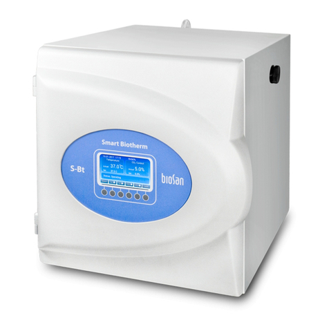
Compact CO incubator S-Bt
2
S-Bt Service Manual - V.1AW Version 1 - October 2017 Page 1
Maintanence
1. If the unit requires maintenance, disconnect the unit from the mains and contact Biosan or your
local Biosan representative.
2. All maintenance and repair operations must be performed only by qualified and specially trained
personnel.
3. Regular service schedule:
After operation
Switch on the recirculator running for 1 to 3 hours in an empty incubator to decontaminate air in
the incubator. After decontamination, slightly open the incubator doors – UV lamp has been
known to produce reactive oxygen species in minor concentrations.
Monthly (more frequently, if necessary)
Rub the inner surfaces, water pan with lid and shelves of the incubator with 75% ethanol solution
or other acceptably disinfectant such as sodium hypochlorite solution, and allow them to dry.
After cleaning the glass door, rinse with water and dry the excess to avoid streaks and possible
corrosion.
Remove dust with moist cloth piece from outer incubator surface, especially front screen and
upper part of the incubator.
Visually check the hydrophobic filter and access port seal and replace if necessary.
Check the accuracy of CO sensor system by measuring the actual CO concentration with a
2 2
reference CO analyzer.
2
Hydrophobic filter. The filter should be replaced when it becomes glazed with dirt. Maximum
time of use is 30 days. We recommend replacing the filter immediately after full cycle of
maintenance.
Access port seal. To prevent possible contamination of access port seal (made from foamed
polyethylene) and to ensure complete sealing of the port, the seal should be replaced after 30
days from the first operation.
UV lamp.
Average lifetime of UV lamps supplied is 9000 h. Replacement is necessary after lamp stops
functioning or at the end of manufacturer specified lifetime. Only the persons who have
completed special training are allowed to perform lamps replacement. UV lamp operation
lifetime is checked and tracked by the incubator. After lamp replacement it is necessary to reset
UV Lamp Hours timer.
S-Bt Service Manual - V.1AW Version 1 - October 2017 Page 2
S-Bt Service Manual - V.1AW Version 1 - October 2017 Page 3
Fault diagnostics
1. The incubator is equipped with an alarm and error system. Active alarms and errors are
appropriately indicated on the display.
Alarms and errors are followed by sound signal that can be turned off by pressing any button.
2. Error text can be found in Menu > Service > Settings > Current Errors. Choose Errors
Reset and confirm to reset the error list.
3. Error list can be found in the table below.
Note: After resolving error issues, error must be reset manually.
4. Alarm text can be found in Menu > Active Alarms. Choose Alarms Reset and confirm to reset
the alarm list.
5. Alarms list can be found in the table below.
Note: After resolving alarm issues, reset alarms manually.
Display text Error description
CO2 Sens. Err. СО2 sensor error
Back Back temperature sensor error
Bott. Bottom temperature sensor error
Left Left wall temperature sensor error
Right Right wall temperature sensor error
Up Top temperature sensor error
Door Door temperature sensor error
Chmb. Temperature sensor in the incubator error
Perimeter T.Sens. Err. Perimeter temperature sensor error
Recirc. Lamp Err. UV lamp error
Communication Err. Error connecting to power board
CO2.Sens.Comm.Err. Error connecting to CO2 sensor board
To enter the Service mode
1. While in menu hold two right buttons for 5 sec. to enter the service mode (unlock grey menu
items).
2. To exit service mode hold two right buttons for 5 sec. or exit from menu to main display.
Display text Description
Temp. High Alarm
Temp. Low Alarm
CO2 High Alarm
CO2 Low Alarm
Low Humidity
UV Lamp Hours > 9000h Lamp reaches end of life time. After replacement reset timer.
(Menu > Service > Recirc. UV Lamp Hours > Hours Reset)
Adjustable limit is exceeded.
(Menu > Service > Settings > Alarm Settings)
S-Bt Service Manual - V.1AW Version 1 - October 2017 Page 4
CO2 valve settings
CO recovery time to 5.0% after opening the door for 1 min, depending on the PWM & Dosage
2
Coef.
PWM 040s (Preset) 010s 060s 040s 010s
Dosage Coef. 1/020 (Preset) 1/020 1/020 1/001 1/001
Recovery time 12 min 3 min 18 min 2 min 45 sec
Possible excess 5.00% 5.10% 5.00% 5.10% 5.80%
S-Bt Service Manual - V.1AW Version 1 - October 2017 Page 5
The following spare parts are available for S-Bt:
No. Spare part Marking Article
1 Hydrophobic filter BS-010425-S35
2 Access port seal Foamed PE (set of 5) BS-010425-S03
3 Fuse FSMO 3,15A BS-000000-S06
4UV lamp TUV-6W T5 BS-010425-S04
5 Battery CR 2032 (Lithium Battery) BS-010425-S16
6 Wireless Interface Board W_Int_V1 BS-010425-S09
7 Control Board Incub_TFT BS-010425-S05
8 LCD Interface Board FTDI VM800C43A-N FT800 EVE MODULE BS-010425-S07
9 LCD TFT LCD 5 inch Display 480x272 BS-010425-S06
10 Button Board INCUB_KEY BS-010425-S08
11 Door Temperature Sensor DS18B20 BS-010425-S32
12 Door Heater 80W Silicone Heater M BS-010425-S24
13 Humidity Sensor Humid_S_V1 BS-010425-S13
14 Sensor Interface Board Sens_interface_V1 BS-010425-S11
15 CO2 Sensor CO2 Engine™ BS-010425-S12
16 UV lamp Ballast QT-ECO 1x4-16/220-240L BS-010425-S17
17 Solenoid valve VX210DZ1JAXB DC 12V BS-010425-S15
18 Power Board INCUB_PWR_V4 BS-010425-S10
19 Switch C1350ALAAFB BS-010425-S20
20 Power Socket PF0033/10/63 BS-010425-S21
21 Fan 632NU ebmpapst BS-010425-S14
22 Chamber Temperature Sensor DS18B20 BS-010425-S34
23 Back Temperature Sensor DS18B20 BS-010425-S28
24 Back Heater 80W Silicone Heater M BS-010425-S24
25 Transformer TTS 100Z 230/2x12V BS-010425-S19
26 Bottom Temperature Sensor DS18B20 BS-010425-S27
27 Perimeter Temperature Sensor DS18B20 BS-010425-S33
28 Port Heater PCB SBTH BS-010425-S26
29 Open Door Sensor HALL_SEN_V1 BS-010425-S22
30 Perimeter Heater PCB BTH BS-010425-S25
31 Left Temperature Sensor DS18B20 BS-010425-S29
31 Right Temperature Sensor DS18B20 BS-010425-S30
31 Top Temperature Sensor DS18B20 BS-010425-S31
32 Bottom Heater 80W Silicone Heater L BS-010425-S23
32 Left Heater 80W Silicone Heater L BS-010425-S23
32 Right Heater 80W Silicone Heater L BS-010425-S23
32 Top Heater 80W Silicone Heater M BS-010425-S24
I. Spare part replacement
1. Hydrophobic filter replacement:
1. Disconnect the unit from power supply.
2. Unscrew the both filter connectors (fig.1/1).
3. Pull off tubes from the filter and remove it.
4. Replace the filter and re-assemble the unit.
Note: Connect filter with appropriate side facing towards IN label on
the unit (on filter side there may be IN or traingle marking).
2. Access port seal replacement:
1. Disconnect the unit from power supply.
2. Unscrew access port cap (fig.2/1).
3. Pull out the seal and replace it.
4. Re-assemble the unit.
3. Fuse replacement:
1. Disconnect the unit from power supply.
2. Pull out fuse drawer ( ).fig.13/1
3. Remove the fuse from the holder.
4. Check and replace with the correct fuse if it is necessary (3.15A).
5. Re-assemble the unit.
4. UV Lamp replacement:
1. Disconnect the unit from power supply.
2. O remove shelves pen the door and unscrew the two screws
(fig.14/1) and remove chamber cover;
3. Unscrew the two Lamp covers (fig.15/7).
4. Pull out Lamp from sockets.
5. Replace the UV Lamp and re-assemble the unit.
Note: After lamp replacement reset Recirc. UV Lamp Hours
Disassembling for the: Control Board, Button Board, Wireless
Interface Board, LCD, LCD Interface Board, Battery, Door
Temperature Sensor , Door Heater.
1. Disconnect the unit from power supply.
2. Unscrew the six screws (fig.3/1) and release door cover.
3. Unscrew one screw (fig.4/1) and release ground wire.
4. Unscrew screws (fig.4/2) and release data and temperature sensor
wires from the control board.
5. Remove door cover.
5. To replace the Battery:
– pull out used Battery from the slot (fig.5/1);
– replace the Battery and re-assemble the unit;
6. To replace the Wireless Interface Board:
– disconnect Wireless Interface Board wires from the control
board (fig.5/3);
– unscrew the two screws (fig.5/2) and release the Board;
– replace the Wireless Interface Board and re-assemble the unit;
7. To replace the Control Board:
– disconnect wireless interface board wires (fig.5/3) from the
Control Board;
– disconnect button board wire terminal (fig.5/4) from the Control Board;
– unscrew the four screws (fig.5/5) and gently pull out Control Board
from LCD interface board pin socket;
– replace the Control Board, install new battery or take from previous board
S-Bt Service Manual - V.1AW Version 1 - October 2017 Page 6
fig.1M
Rear view
1
fig.2M
Access port
1
2
fig.3M
Opened door
fig.4M
Door cover removed
1
123 4
2
8. To replace the LCD Interface Board:
– remove the control board (see the control board replacement);
– pull out display cable from the slot (fig.6/1) by releasing
side clips;
– unscrew the four screws (fig.6/2) and release the board;
– replace the LCD Interface Board and re-assemble the unit.
Note: Keep ferrites on display cable.
9. To replace the LCD :
– remove the control board (see the control board
replacement);
– remove the LCD interface board (see the LCD interface
board replacement);
– unscrew the four screws (fig.6/3) and remove display holders;
– remove grounding copper layer (fig.6/4);
– replace the LCD and re-assemble the unit.
Note: Install grounding copper layer on a new LCD.
10. To replace the Button Board:
– disconnect Button Board wire terminal (fig.5/4) from
the control board and Button Board;
– unscrew the three screws (fig.6/5) and release the board;
– replace the Button Board and re-assemble the unit.
11. To replace the Door Temperature sensor:
– remove thermal insulation spot (fig.4/4);
– unscrew the two screws (fig.8/1) and remove cover and cushion;
– remove heat shrink sleeve (fig.8/2);
– desolder temperature sensor wires and remove it;
– solder new temperature sensor (1. scheme);
– re-assemble the unit.
12. To replace the Door Heater:
– unscrew the two screws (fig.4/3) and release Heater wires;
– unscrew the two screws (fig.7/1) and release ground wires;
– tear off insulation layer;
– tear off Door Heater (fig.7/2);
– replace the Door Heater and re-assemble the unit.
Disassembling for the: Power Board, Sensor Interface Board,
CO Sensor, Humidity Sensor, Fan, Solenoid Valve, UV Lamp
2
Ballast, Switch, Power Socket, Chamber Temperature
Sensor, Back Temperature Sensor, Back heater:
1. Disconnect the unit from power supply.
2. Unscrew the six screws (fig.1/2) on rear part of the unit.
3. Pull rear cover gently backward and disconnect two tubes (fig.9/1);
4. Remove rear cover.
13. To replace the Humidity Sensor:
– open the door and unscrew the two screws (fig.14/1) and remove
chamber cover;
– disconnect Humidity Sensor wire terminal from the sensor interface
board (fig.11/1);
– unscrew the nut (fig.15/1) and remove Humidity Sensor assembly;
– replace the Humidity Sensor assembly and re-assemble the unit;
Note: It is important to install new sensor PCB in vertical position as
shown in fig.11/2.
S-Bt Service Manual - V.1AW Version 1 - October 2017 Page 7
fig.6M
LCD interface board
fig.5M
Control board
12345
123 4 5
fig.7M
Door heater
fig.8M
Door temperature sensor
12
12
S-Bt Service Manual - V.1AW Version 1 - October 2017 Page 8
14. To replace the Sensor Interface Board:
– open the door and remove shelves unscrew the, two screws
(fig.14/1) and remove chamber cover;
– disconnect data wire from the Sensor Interface Board (fig.11/5);
– unscrew the nut (fig.14/2) an release CO sensor
2
d ;
– unscrew the ( ) and Sensor Interface two screws fig.11/3 release
Board with ;CO sensor
2
– unscrew the ( ) and gently pull out two screws fig.11/4 CO sensor
2
from Sensor Interface Board pin socket;
– replace the Sensor Interface Board and re-assemble the unit;
15. To replace the :CO sensor
2
– open the door and , unscrew the two screws remove shelves
(fig.14/1) and remove chamber cover;
– disconnect data wire from the sensor interface board (fig.11/5);
– unscrew the nut (fig.14/2) an release CO sensor
2
d ;
– unscrew the ( ) and Sensor Interface two screws fig.11/3 release
Board with ;CO sensor
2
– unscrew the ( ) and gently pull out two screws fig.11/4 CO sensor
2
from sensor interface board pin socket;
– replace the and re-assemble the unit;CO sensor
2
16. To replace the UV Lamp Ballast:
– mark wires with their connection slots to ease the assembling;
– push knobs (fig.12/2) to release the wires;
– unscrew the two screws (fig.12/1) and remove the UV Lamp Ballast;
– replace the UV Lamp Ballast and re-assemble the unit.
17. To replace the Solenoid Valve:
– disconnect tube (fig.10/4) from Solenoid Valve;
– disconnect Solenoid Valve wires (fig.10/1) from the power board;
– unscrew the nut (fig.10/2) from CO supply port;
2
– unscrew the two screws (fig.10/3) and remove Solenoid Valve with
bracket;
– unscrew the two screws and release the bracket;
– replace the Solenoid Valve and re-assemble the unit.
18. To replace the Power Board:
– mark wires with their connection slots to ease the assembling;
– disconnect all wires from the Power Board;
– unscrew the five screws (fig.10/5) and remove the Power Board;
– replace the Power Board and re-assemble the unit.
19. To replace the Switch:
– disconnect the wires (fig.13/3) from the Switch;
– pull out the Switch and replace it;
– re-assemble the unit.
20. To replace the Power Socket:
– disconnect the wires (fig.13/4) from the Power Socket;
– unscrew the ( ) and Power Socket;two screws fig.13/2 release
– remove fuses (see fuse replacement);
– replace the Power socket, install fuses and re-assemble the unit.
scheme.1
fig.9M
Opened rear cover
1
fig.10M
Rear cover removed
fig.11M
Sensor interface board
123
45
12345 6
2
78
9 10
6
S-Bt Service Manual - V.1AW Version 1 - October 2017 Page 9
21. To replace the Fan:
– open the door and remove shelves, unscrew the two screws (fig.14/1)
and remove chamber cover;
– unscrew the two screws 10 6 and release Fan wires;(fig. /)
– remove UV lamp (see UV lamp replacement);
– disconnect UV lamp wires from ballast (see ballast replacement);
– unscrew the screws 15 4 and release lamp holder bracket;(fig. /)
– unscrew the two nuts 15 3 and release Fan holder bracket;(fig. /)
– loosen wire transfer port;
– pull out Fan holder bracket and unscrew the four screws 15 5 of (fig. /)
malfunctioning Fan;
– replace the Fan and re-assemble the unit.
22. To replace the Chamber Temperature Sensor:
– open the door and remove shelves, unscrew the two screws (fig.14/1)
and remove chamber cover;
– remove Temp. Sensor insulation layer (fig.9/2);
– release Chamber Temperature Sensor wires from the power board;
– unscrew the 1 6 and Chamber Temperature Sensor nut (fig. 5/ )remove
assembly;
– replace Chamber Temperature Sensor assembly;
– re-assemble the unit;
23. To replace the Back Temperature Sensor:
– remove the power board (see power board replacement);
– remove the sensor interface board (see sensor interface board
replacement);
– unscrew the four screws (fig.10/10) and remove rear cover;
– remove heat insulation layer (fig.11/6);
– unscrew the appropriate two screws (fig.8/1) and remove cover and
cushion;
– remove heat shrink sleeve (fig.8/2);
– desolder Temperature Sensor wires and remove it;
– solder new Temperature Sensor (1. scheme);
– re-assemble the unit.
24. To replace the Back Heater:
– remove the power board (see power board replacement);
– remove the sensor interface board (see sensor interface board
replacement);
– unscrew the four screws (fig.10/10) and remove rear cover;
– remove heat insulation layer (fig.11/6);
– remove back temperature sensor (see back temperature sensor
replacement);
– tear off Back Heater;
– replace the Heater and re-assemble the unit.
Disassembling for the: Transformer, Port Heater, Bottom
Temperature Sensor, Perimeter Temperature Sensor.
1. Disconnect the unit from power supply.
2. Turn the unit upside down.
3. Unscrew the sixteen screws fig(16/1).
4. Turn around underside cover and unscrew one screw to release
ground wire, remove cover.
25. To replace the Transformer:
– mark the wires with appropriate connection slots;
– unscrew the five screws and release Transformer wires from wire
terminal (fig.17/1);
– unscrew the screw (fig.17/2) and release the Transformer;
– replace the Transformer and re-assemble the unit.
fig.12M
UV lamp ballast
12
1
2
fig.13M
Power socket
3
4
1
12
fig.14M
Opened door
fig.15M
Chamber cover removed
3 45 6
7
2
S-Bt Service Manual - V.1AW Version 1 - October 2017 Page 10
26. To replace the Bottom Temperature Sensor:
– unscrew the two screws (fig.17/4) and remove cover and cushion;
– remove heat shrink sleeve;
– desolder temperature sensor wires and remove it;
– solder new temperature sensor (1. scheme);
– re-assemble the unit.
27. To replace the Perimeter Temperature Sensor:
– unscrew the two screws (fig.17/3) and remove cover and cushion;
– remove heat shrink sleeve;
– desolder temperature sensor wires and remove it;
– solder new temperature sensor (1. scheme);
– re-assemble the unit.
28. To replace the Port Heater:
– unscrew access port cap (fig.2/1);
– disconnect Port Heater wire from the wire terminal (fig.17/1);
– unscrew the port end (fig.14/2) from inside of the chamber;
– unscrew the screw (fig.2/2) and pull out cable access port (fig.18);
– remove heat resistant tape (fig.18/1);
– remove Port Heater board (fig.18/2);
– replace Port Heater board, fix it using heat resistant tape;
– re-assemble the unit.
Disassembling for the: Open Door Sensor; Top, Bottom, Left,
Right - Heaters; Left, Right, Top - Temperature Sensors.
1. Disconnect the unit from power supply.
2. Unscrew the six screws (fig.1/2) on rear part of the unit.
3. Pull rear cover gently backward and disconnect two tubes (fig.9/1);
4. Remove rear cover.
5 .Turn the unit upside down.
6. Unscrew the sixteen screws (fig.16/1).
7. Turn around underside cover and unscrew one screw to release
ground wire, remove cover.
8. Unscrew the four spacers (fig.17/5).
9. Disconnect the wires from transformer wire terminal (fig.17/1).
10. Remove the solenoid valve (see solenoid valve replacement).
11. Remove the power socket (see power socket replacement).
12. Remove the switch (see switch replacement).
13. Remove the CO sample port (fig.10/8).
2
14. Remove the cable access port (see port heater replacement).
15. Unscrew the three screws (fig.10/7) and remove switch bracket.
16. Unscrew the six screws (fig.16/2) and release working chamber.
17. Open the door and gently pull out working chamber.
29. To replace the Open Door Sensor:
– disconnect Open Door Sensor wires (fig.10/9) from the power
board;
– pull out Open Door Sensor from the slot (fig.19/1);
– clean excess silicone;
– replace Open Door Sensor, fix it in the slot using silicone;
– re-assemble the unit.
fig.18M
Cable access port removed
1
2
fig.19M
Working chamber removed
12
fig.16M
Underside
1
2
fig.17M
Underside cover removed
1
2
3 4 5
S-Bt Service Manual - V.1AW Version 1 - October 2017 Page 11
30. To replace the Perimeter Heater:
– unscrew the nine nuts (fig.19/2) and release Perimeter Heater PCB’s;
– detect malfunctioning Perimeter Heater PCB;
– desolder the connecting wires;
– tear off malfunctioning Perimeter Heater PCB from aluminium base;
– replace the Perimeter Heater PCB and re-assemble the unit.
Note: use heat resistant glue to fix Perimeter Heater PCB.
31. To replace the Left, Right, Top Temperature Sensor:
– unscrew the appropriate two screws (fig.8/1) and remove cover and
cushion;
– remove heat shrink sleeve (fig.8/2);
– desolder temperature sensor wires and remove it;
– solder new temperature sensor (1. scheme);
– re-assemble the unit.
32. To replace the Top, Bottom, Left, Right Heater:
– unscrew the two screws and release appropriate Heater wires from the
power board according to the schematics;
– remove appropriate temperature sensor (see top, bottom, left, right
temperature sensor replacement);
– tear off appropriate Heater (fig.20/1);
– replace the Heater and re-assemble the unit.
fig.20M
Working chamber
1
II. Electrical Safety tests
With the unit disconnected from the AC power supply, and the power supply lead plugged into
the unit, perform the following safety tests before returning the unit to the customer.
- Earth Bonding Test
Use a low resistance measuring instrument to check that the resistance between unit
chassis and power cable earth connector is less than 0.1 ohm.
- Insulation Resistance Test
Connect the live and neutral pins of the power supply plug together. Use a 500V insulation
resistance tester and measure the insulation resistance between the earth and live/neutral
pins. This should be greater than 2 Mohm.
S-Bt Service Manual - V.1AW Version 1 - October 2017 Page 12
S-Bt Service Manual - V.1AW Version 1 - October 2017 Page 13
Power Board
Temperature Sensors
Open Door
Sensor
Switch
Power Socket
Ballast
UV Lamp
Heaters
Perimeter Heater
Wire Port Heater
Transformer
Humidity
Sensor
CO2 Sensor Sensor
Interface
Board
S-Bt Service Manual - V.1AW Version 1 - October 2017 Page 14
Button Board
LCD
LCD Interface Board
Temperature
Sensor
Wireless Interface
Door Heater
Control Board
S-Bt Service Manual - V.1AW Version 1 - October 2017 Page 15
S-Bt
Code Item Count
A0 PCB INCUB_PWR_V4 1
A1...A7,A19 Dallas DS18B20 Temperatue Sensor 8
A8 PCB HALL_SEN_V1 1
A9 Ballast OSRAM QUICKTRONIC QT-ECO 1x4-16 /220-240L 1
A10 BULGIN - PF0033/10/63. - INLET, IEC, FUSED, PANEL 1
A11 CO2 Engine™ ICB diffusion model + connector for CO2 MULTICOMP 1
A12 PCB Sens_interface_V1 1
A13 PCB Humid_S_V1 1
A14 PCB INCUB_KEY 1
A15 PCB Incub_TFT 1
A16 PCB W_Int_V1 1
A17 TFT LCD 5 inch Display 480x272 1
A18 FTDI VM800C43A-N FT800 EVE MODULE, FPC/FFC 40 LCD CONN 1
M1,M2 632NU ebmpapst 2
2 Ferrites Würth Elektronik 742 721 0 2
S1 ARCOLECTRIC SWITCHES - C1350ALAAFB ,DPST, BLACK 1
H1.1...H1.4 PCB BTH (almiko) 4
H2 PCB SBTH (almiko) 1
H3...H8 230V/115V 80W Silicone Heater (BT50-001) 6
F1,F2 LITTELFUSE 02153.15MXP FUSE, 3.15A, TIME DELAY 2
HL1 LAMP TUV-6W T5 PHILIPS 1
TR1 TTS 100Z 230/2x12V 1
D SF38 (Must be installed inside socket of solenoid) 1
SOLENOID VX210DZ1JAXB DC 12V 1
Battery CR 2032 (Lithium Battery) 1
X1...X2 G5 Lampholders T5 2
X3 MOLEX - 22-01-2045 - CRIMP HOUSING, 2.54MM, 4WAY 1
X4 MULTICOMP-MC6FD016-30P1SOCKET,IDC,S/RELIEF, 16W 1
X5 MULTICOMP MC6FD010-30P1, 6F Receptacle, 10, 2.54 mm 1
S-Bt Service Manual - V.1AW Version 1 - October 2017 Page 16
Wireless Interface Board W_Int_V1 contains Class 1 Bluetooth® Module — RN41-I/RM
with EDR Support, manufacturer Microchip specification
Features
• Fully qualified Bluetooth® version 2.1 module, supports version 2.1 + Enhanced Data Rate (EDR)
• ASCII command interface over UART
• Postage-stamp sized form factor:
- RN41: 13.4 x 25.8 x 2 mm
- RN41N: 13.4 x 20 x 2 mm
• Low-power (30 mA connected, < 10 mA sniff mode)
• UART (SPP or HCI) and USB (HCI only) data connection interfaces
• Sustained SPP data rates: 240 Kbps (Slave mode), 300 Kbps (Master mode)
• HCI data rates: 1.5 Mbps sustained, 3.0 Mbps burst in HCI mode
• Embedded Bluetooth stack profiles include: GAP, SDP, RFCOMM, L2CAP protocols, with SPP, HID, and
DUN profile support (does not require any host stack).
• Bluetooth SIG qualified, end product listing
• Castellated SMT pads for easy and reliable PCB mounting
• Class 1 high-power amplifier with on-board ceramic chip antenna (RN41) or external antenna (RN41N)
• Compliance:
- Modular Certified for the United States (FCC) and Canada (IC)
- European R&TTE Directive Assessed Radio Module
- Australia/New Zealand/Korea/Taiwan/Japan
- Bluetooth SIG QDID
• Integrated Crystal, Internal Voltage Regulator, Matching Circuitry, Power Amplifier, Low Noise, Memory
Amplifier and PCB Antenna
• Easy Integration into Final Product - Minimize Product Development, Quicker Time to Market
• Compatible with Microchip Microcontroller Families (PIC16F, PIC18F, PIC24F/H, dsPIC33 and PIC32)
• Up to 100 meter range
Full datasheet available at:
http://ww1.microchip.com/downloads/en/devicedoc/50002280a.pdf
RN41-I/RM details:
RN41: Device: - UART, Ceramic Chip Antenna
I: Temperature Range: -40°C to +85°C
RM: Radio Module, latest firmware version 6.30

Other Biosan Laboratory Equipment manuals
Biosan Assistboy User manual

Biosan

Biosan Assistboy User manual

Biosan RTS-1C User manual

Biosan

Biosan RTS-1C User manual

Biosan OD Plate User manual

Biosan

Biosan OD Plate User manual

Biosan WB-4MS User manual

Biosan

Biosan WB-4MS User manual

Biosan CH-100 User manual

Biosan

Biosan CH-100 User manual

Biosan MMS-3000 User manual

Biosan

Biosan MMS-3000 User manual

Biosan BioMagPure 12 Plus User manual

Biosan

Biosan BioMagPure 12 Plus User manual

Biosan PSU-10i User manual

Biosan

Biosan PSU-10i User manual

Biosan Automatic Luminescence Analyser ALA1/4 User manual
Biosan

Biosan Automatic Luminescence Analyser ALA1/4 User manual

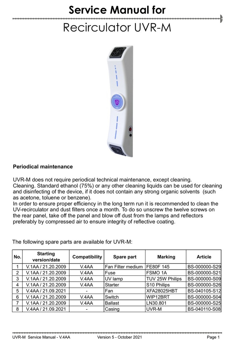
Biosan UVR-M User manual

Biosan

Biosan UVR-M User manual

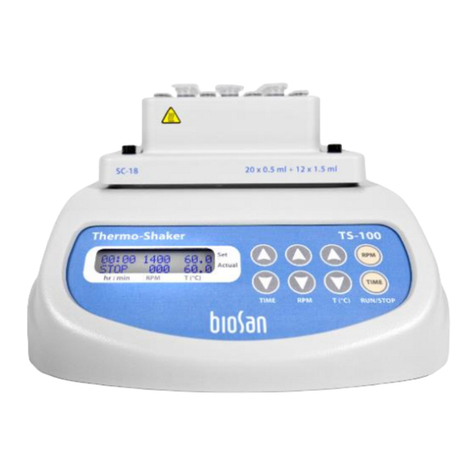
Biosan TS-100 User manual

Biosan

Biosan TS-100 User manual

Biosan DEN-1B User manual

Biosan

Biosan DEN-1B User manual

Biosan Bio RS-24 User manual

Biosan

Biosan Bio RS-24 User manual

Biosan UVC-AR User manual

Biosan

Biosan UVC-AR User manual

Biosan RCP-24 User manual

Biosan

Biosan RCP-24 User manual

Biosan Bio RS-24 User manual

Biosan

Biosan Bio RS-24 User manual

Biosan LMC-4200R User manual

Biosan

Biosan LMC-4200R User manual

Biosan Multi Bio 3D User manual

Biosan

Biosan Multi Bio 3D User manual

Biosan LMC-56 User manual

Biosan

Biosan LMC-56 User manual

Biosan MMS-3000 User manual

Biosan

Biosan MMS-3000 User manual

Biosan S-Bt Smart BioTherm User manual

Biosan

Biosan S-Bt Smart BioTherm User manual

Biosan ES-20/80C User manual

Biosan

Biosan ES-20/80C User manual

Biosan Vortex MSV-3500 User manual

Biosan

Biosan Vortex MSV-3500 User manual

Biosan Microspin FV-2400 User manual

Biosan

Biosan Microspin FV-2400 User manual

Popular Laboratory Equipment manuals by other brands
Gilson Trackman user manual

Gilson

Gilson Trackman user manual

Omni Bead Ruptor 4 user manual

Omni

Omni Bead Ruptor 4 user manual

Hoefer SE 260 user manual

Hoefer

Hoefer SE 260 user manual

Thermo Scientific Fisher Scientific Fisherbrand GT1R... instruction manual

Thermo Scientific

Thermo Scientific Fisher Scientific Fisherbrand GT1R... instruction manual

Thermo Scientific Sorvall ST 8FR instruction manual

Thermo Scientific

Thermo Scientific Sorvall ST 8FR instruction manual

Thermo Scientific 8121 PLC-230 LP Operating and maintenance manual

Thermo Scientific

Thermo Scientific 8121 PLC-230 LP Operating and maintenance manual

Biotage PRESSURE+ 96 user manual

Biotage

Biotage PRESSURE+ 96 user manual

Hach LS 120 user manual

Hach

Hach LS 120 user manual

Sakura Cyto-Tek 2500 Quick reference guide

Sakura

Sakura Cyto-Tek 2500 Quick reference guide

lbx WB01 Series user manual

lbx

lbx WB01 Series user manual

KERN PFB 120-3A operating manual

KERN

KERN PFB 120-3A operating manual

Sonation PRSO-V1 user manual

Sonation

Sonation PRSO-V1 user manual

Bürkle StickProof 5338-0410 Directions for use

Bürkle

Bürkle StickProof 5338-0410 Directions for use

vacuubrand MV 10C NT VARIO o.C. Instructions for use

vacuubrand

vacuubrand MV 10C NT VARIO o.C. Instructions for use

Steinberg Systems SBS-LA-25 user manual

Steinberg Systems

Steinberg Systems SBS-LA-25 user manual

REITEL ROTOGRIND NT operating instructions

REITEL

REITEL ROTOGRIND NT operating instructions

Puls POE.8AT-DC1 installation manual

Puls

Puls POE.8AT-DC1 installation manual

Daihan Scientific ThermoStable SOV-20 user manual

Daihan Scientific

Daihan Scientific ThermoStable SOV-20 user manual

manuals.online logo
manuals.online logoBrands
  • About & Mission
  • Contact us
  • Privacy Policy
  • Terms and Conditions

Copyright 2025 Manuals.Online. All Rights Reserved.