63057 92022
-
Gateway S-Link
MC_0366
NMEA0183 Interface
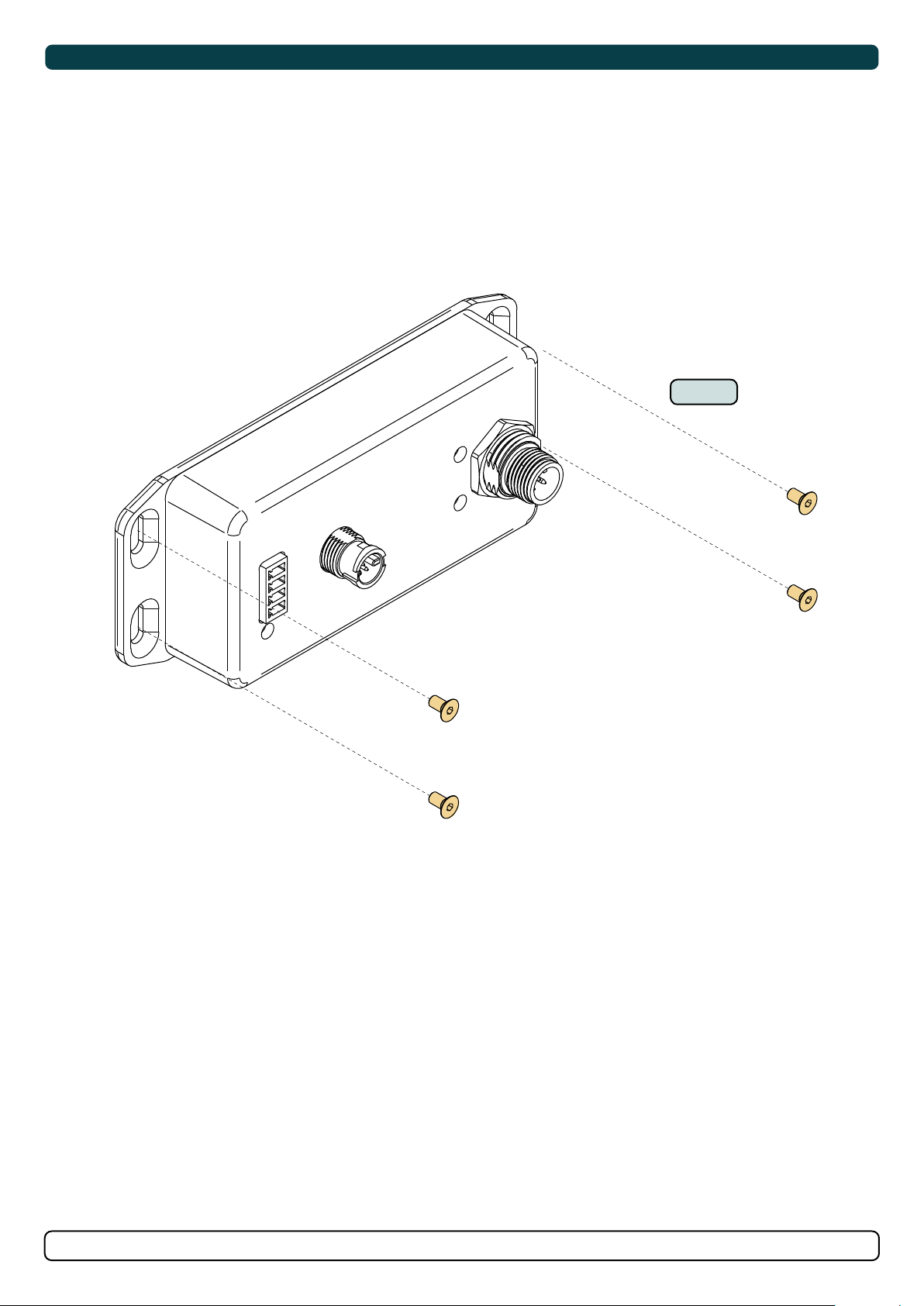
Connection
The V OUT pin can feed power to a single GPS antenna with maximum 100mA, and it is internally fused. V OUT is S-link bus voltage. RX A(+) & TX B(-)
are galvanic isolated
Baud rate
4800 baud and 38400 baud is supported, and are set automatically.
Supported NMEA0183 sentences
$GxRMC sentences from all positioning systems is supported.
LED indication
LED off: No valid NMEA0183 GPS signals.
LED flashing: Flashing 100ms on and 100 off for each valid GPS message received.
- Valid GPS antenna message at 38400 baud normal flashing on/off (100ms/100ms).
- Valid GPS antenna message at 4800 baud normal flashing on/off (100ms/900ms)
GNSS Antenna Prioritization
GNSS antennas priority sequence is 1. NMEA0183 with 100ms update rate 2. NMEA2000 3. NMEA0183 with 1000ms update rate.
GW-1 will only forward one of the NMEA2000 GPS antenna signal to S-link if more than one antennas is present on the NMEA2000 bus.
If more than one GW-1 have GNSS signal(s) then GW-1’s will prioritize on antenna type from the list above and only one GW-1 will broadcast
GNSS signals on the S-link bus.
All this requires GW-1 rmware V1.021 or newer.
Status LED
LED off: No power to the device.
LED on: S-Link communication and power OK.
LED flashing (on/off (500ms/500ms)): No S-Link communication but power is OK.
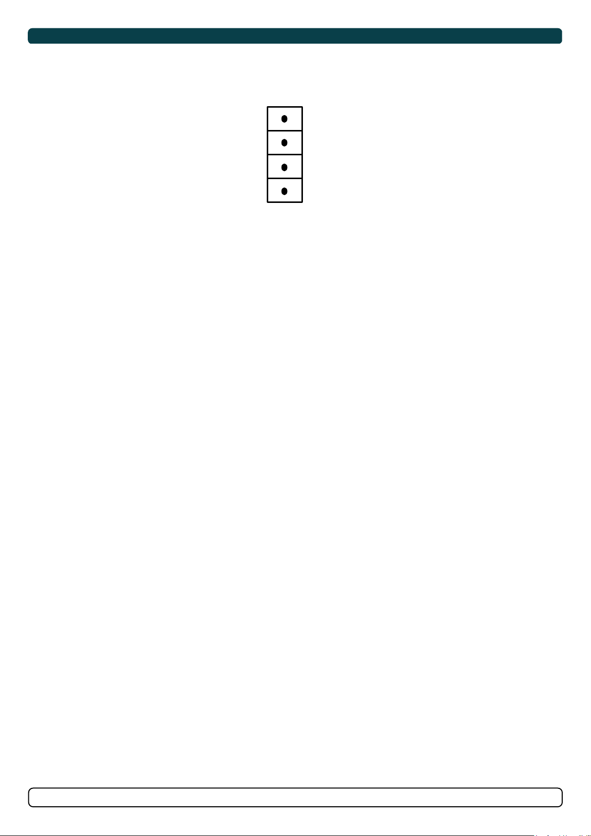
V OUT
GND
RX (-)
RX(+)
When installing an S-Link™ system DO NOT connect any other control equipment directly to the S-Link™ bus except original Sleipner S-Link™ products.
In case of connecting third-party equipment, it must always be connected through a Sleipner-supplied interface product.
Any attempt to directly control or connect into the S-Link™ control system without a designated and approved interface will render all warranties and
responsibilities of all of the connected Sleipner products.
If you are interfacing the S-Link™ bus by agreement with Sleipner through a designated Sleipner supplied interface, you are still required to install at
least one original Sleipner control panel to enable efcient troubleshooting if necessary. MC_0105
The installer must read this document to ensure necessary familiarity with the product before installation.
Instructions in this document cannot be guaranteed to comply with all international and national regulations. It is the responsibility of the
installer to follow all applicable international and national regulations when installing Sleipner products.
The recommendations given in this document are guidelines ONLY, and Sleipner strongly recommends that advice is obtained from a person
familiar with the particular vessel and applicable regulations.
This document contains general installation instructions intended to support experienced installers. If you are not skilled in this type of work,
please contact professional installers for assistance.
If required by local regulation, electrical work must be done by a licensed professional.
Appropriate health and safety procedures must be followed during installation.
Faulty installation of Sleipner products will render all warranties given by Sleipner Motor AS.
MC_0038
Responsibility of the Installer