Contents
Assembly/Disassembly Instructions..........................................................................................................................................................................1
Flushometer Valve Parts List (including Replacement and Repair Kits) ................................................................................................................2
Flushometer Models and Variations..........................................................................................................................................................................3
Troubleshooting Guide (including Care and Cleaning Instructions) ........................................................................................................................4
Sloan Valve Company can also provide
products not shown in our current
catalog. If you have any questions about
our products or any installation issues,
please contact the Installation
Engineering staff at 1-800-982-5839.
LIMITED WARRANTY
Sloan Valve Company warrants its Flushometer Products to be made of first
class materials, free from defects of material or workmanship under normal
use and to perform the service for which they are intended in a thoroughly
reliable and efficient manner when properly installed and serviced for a period
of 3 years (1 year for special finishes) from date of purchase. During this
period, Sloan Valve Company will, at its option, repair or replace any part or
parts which prove to be thus defective if returned to Sloan Valve Company, at
customer’s cost, and this shall be the sole remedy available under this
warranty. No claims will be allowed for labor, transportation or other
incidental costs. This warranty extends only to those persons or organizations
who purchase Sloan Valve Company’s products directly from Sloan Valve
Company for purpose of resale.
THERE ARE NO WARRANTIES WHICH EXTEND BEYOND THE DESCRIPTION ON
THE FACE HEREOF. IN NO EVENT IS SLOAN VALVE COMPANY RESPONSIBLE
FOR ANY CONSEQUENTIAL DAMAGES OF ANY MEASURE WHATSOEVER.
FLUSHOMETERS
Maintenance Guide
The information contained in this document is subject to change without notice.
Dolphin M.G.– Rev. 0 (12/99) Code No. 0816336
•DOLPHIN
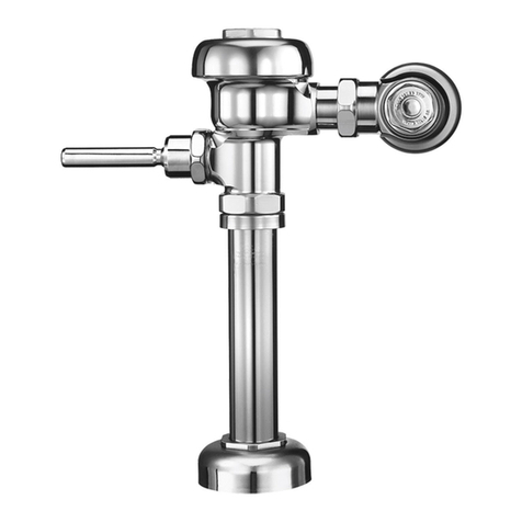
Assembly of Dolphin Flushometer
1. Insert DO-9 Stem into bottom of Upper Body using twist
and push action to prevent damaging O-rings.
2. Engage fork of Handle Assembly in notch of Stem.
Handle should align perfectly.
3. Depress Handle and insert DO-7 Piston Spring.
4. Place DO-5 Piston (with O-ring toward top) onto Spring
and press into chamber.
5. Assemble DO-4 Stem Nut to Stem (with knurled surface
toward top) and down into stem. Engage tips of DO-28
Retaining Ring into slot of Stem and snap onto Stem.
6. Assemble DO-14 Bushing into bottom of Stem, mating
groove of bushing into groove of Handle socket.
7. With assembly still in inverted position, depress handle
and hold.
8. Place DO-16 Spring on Stem.
9. With Handle depressed, place DO-15 Flex-Sac and DO-18
Seating Nut on Stem. Pressing down with palm of hand,
screw Seating Nut clockwise until firm engagement is made
with DO-14 Bushing.
10. Assemble upper Body assembly to lower Body assem
bly and tighten four (4) DO-11 Cover Screws.
11. Fill upper chamber to top with SAE 10 oil. Work Handle
several times and add additional oil on top. Replace and
tighten DO-1 Cover Nut.
12. Turn on water supply at Control Stop.
Disassembly of Dolphin Flushometer
1. Turn off water at Control Stop.
2. Loosen DO-1 Cover Nut but do not remove.
3. Unscrew four (4) DO-11 Cover Screws
and lift off top section of valve
(keep in vertical position to
prevent oil from spilling).
4. Remove DO-1 Cover Nut.
5. Pour oil into clean container.
6. Unscrew DO-15 Flex-Sac and
DO-18 Seating Nut.
7. Remove DO-16 Compression Spring.
8. Depress Handle to raise Piston Assembly.
9. Remove DO-28 Retaining Ring from Stem.
10. Remove DO-4 Stem from bottom of Body with a gradual
twist and pull action to prevent damaging O-rings.
11. Remove DO-14 Bushing.
12. Remove DO-5 Piston from chamber.
13. Remove DO-7 Spring.
14. Disengage Handle Assembly and Socket by pulling outward.
15. Remove DO-9 Stem from bottom of Body with a gradual
twist and push action to prevent damaging O-rings.

