SMAJAYU JY305 User manual

Add: Room 213-214, Building 1, Mingliang Science Park, No. 88, Zhuguang North Road, Taoyuan
Street, Nanshan District, Shenzhen, China,518055 Tel: +86-075586276295
Operation Manual JY305
Smajayu 2.0
JY305 Install Video:
ttsyotbeomat2
JY305 related video:
The latest software download link:
JY305 calibration training video

Add: Room 213-214, Building 1, Mingliang Science Park, No. 88, Zhuguang North Road, Taoyuan
Street, Nanshan District, Shenzhen, China,518055 Tel: +86-075586276295
Content
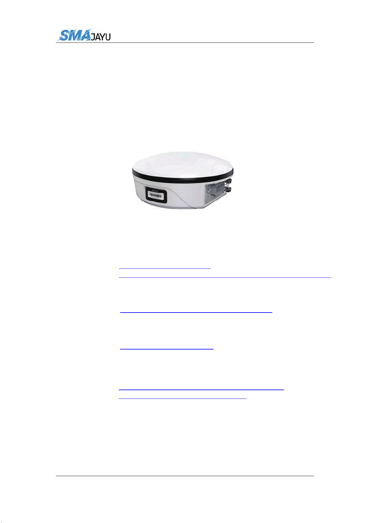
1、Introduction.................................................
2、Mai ................................................................................. 4
3、Device Switching .................................................................................. 6
4、Equipment Debugging .......................................................................... 7
4.1、Main Interface Introduction .......................................................7
4.2、Vehicle Parameters .....................................................................9
4.3、Base Station Connection ..........................................................10
4.4、Device Registration ..................................................................12
4.5、Equipment Debugging ............................................................. 13
4.5.1、Mode Selection ............................................................. 14
4.5.2、Roll Debugging .............................................................18
4.5.3、Error Debugging ........................................................... 20
4.6、AB Line Setting ....................................................................... 21
4.7、Error Debugging ...................................................................... 23
5、Function Introduction ..........................................................................23
5.1、Language Selection ..................................................................23
5.2、Software Upgrade .................................................................... 24
5.3、Time Selection ......................................................................... 24
5.4、Unit Selection ...........................................................................25
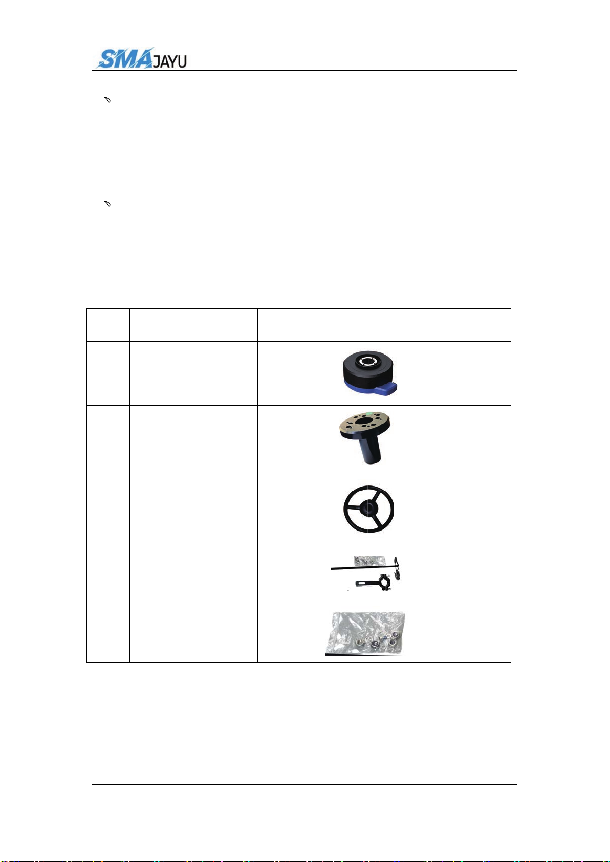
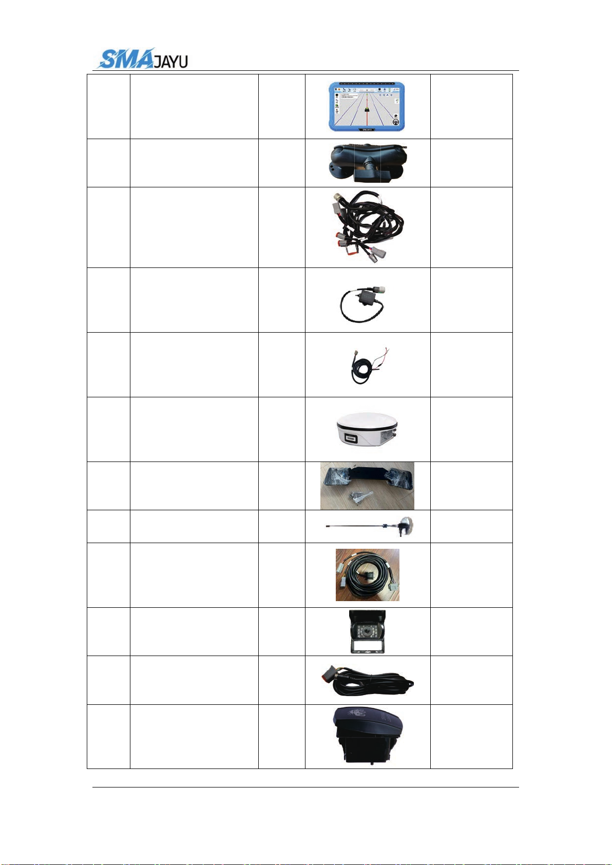
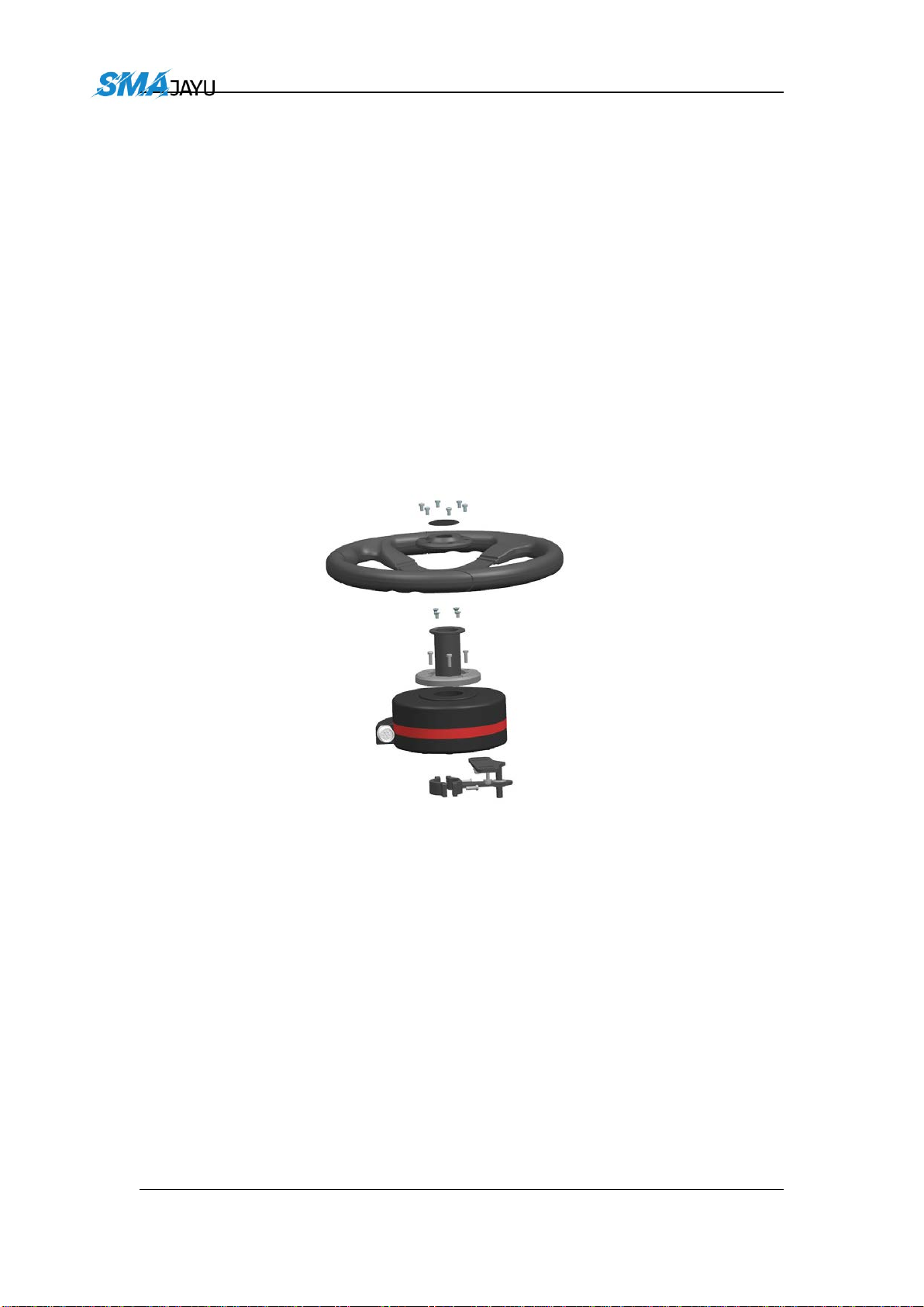
2.1
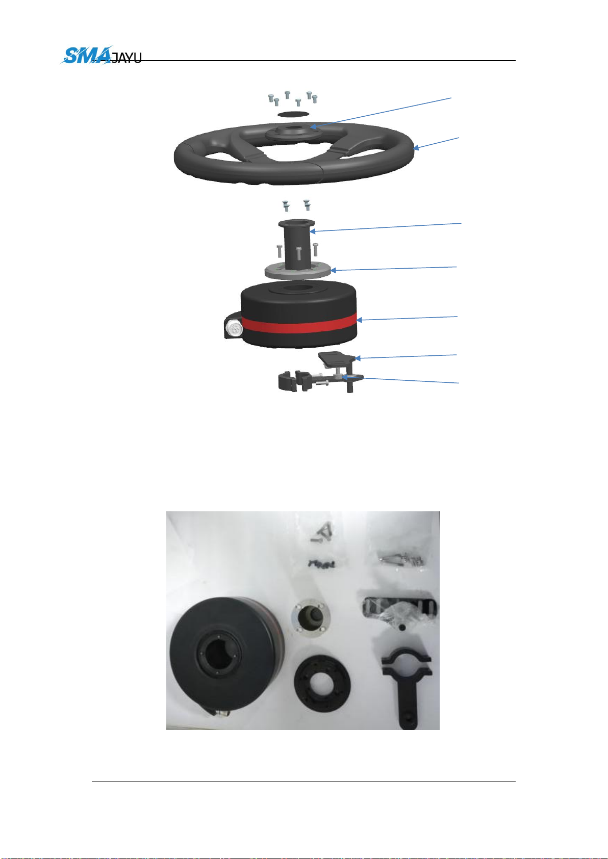
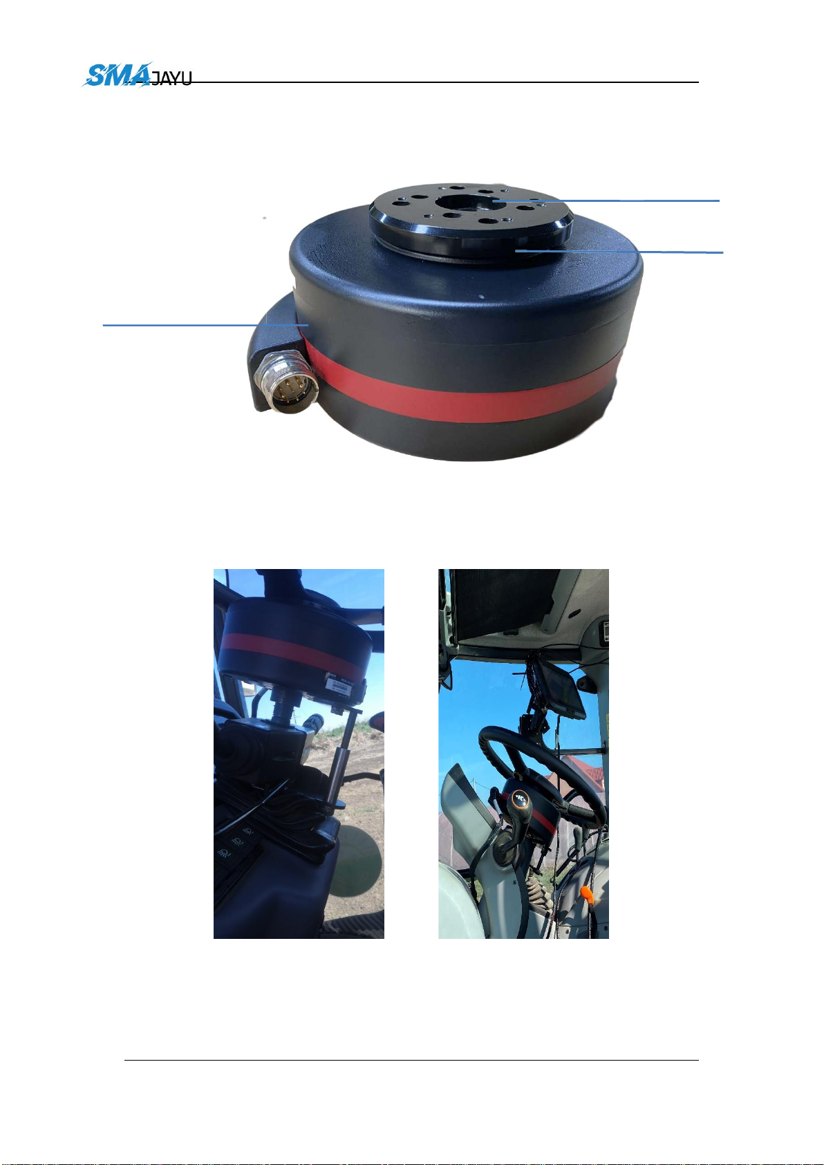
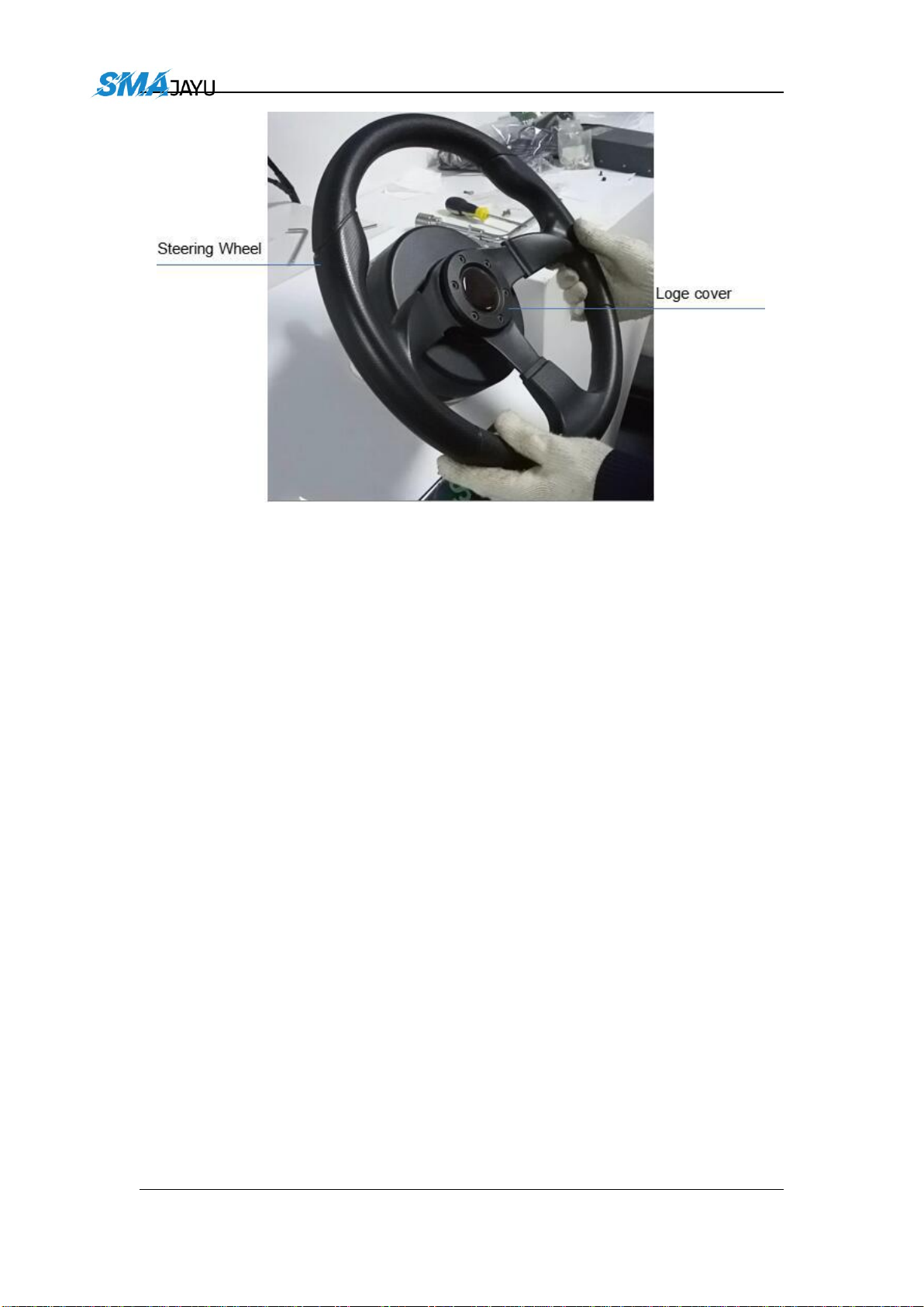
Assembly and Installation .........................................................

dd Room 213-214, Building 1, Mingliang Science Park, No. 88, Zhuguang North Road, Taoyuan
Street, Nanshan District, Shenzhen, hina,18 Tel 8-822
5.7、Camera ..................................................................................... 26
6、Equipment Specifications ................................................................... 27
6.1、T100 Tablet .............................................................................. 27
6.1.1、Technical Features ........................................................ 28
6.1.2、Technical Parameter ......................................................29
6.1.3、Interface Definition .......................................................30
6.2、2 Motor ............................................................................ 32
6.2.1、Introduction ...................................................................32
6.2.2、Technical Features ........................................................ 32
6.2.3、Technical Parameter ......................................................33
6.2.4、Interface Definition .......................................................34
6.3、 Receiver ............................................................................35
6.3.1、Technical Features ........................................................ 35
6.3.2、Technical Parameter ......................................................36
6.3.3、Interface Definition .......................................................38
5.5、Day and Night Mode Switching .............................................. 25
5.6、Dimension Switching ...............................................................26

dd Room 213-214, Building 1, Mingliang Science Park, No. 88, Zhuguang North Road, Taoyuan
Street, Nanshan District, Shenzhen, hina,18 Tel 8-822
1、Introduction
2、Main Accessories
This equipment mainly includes five parts: tablet T100, drive control
motor , receiver , angle sensor (optional), and connecting
cable.
Details as the list below:
NO. Description Qty Picture Remark
1 Drive control motor 1
2 spline 1 Optional
3 steering wheel 1 41cm
4bracket 1Optional
5 Bracket screw pack 1

dd Room 213-214, Building 1, Mingliang Science Park, No. 88, Zhuguang North Road, Taoyuan
Street, Nanshan District, Shenzhen, hina,18 Tel 8-822
6tablet 1 T100
7RAM bracket 1
8T100-Fourth
generation main line 1
9switch line 1
10 Power supply
extension line 1
11 GNSS Receiver 1
12 Mounting plate 1
13 radio antenna 1
14 HW- Power supply
line 1
15 Waterproof camera 1
16 Camera extension
cable 1
17 Manual switch 1

2.1
Assembly and Installation
2.1.1 EMS2 installation
The EMS2 Motor Wheel is an electric motor steering wheel. The most
important part is the spline sleeve, which is based on the selection of
the vehicle model refer to the table in Appendix. Please indicate
your vehicle model before placing order of this system. The
other components include Loge cover, steering wheel, flange,
bracket and screws which are shown as below.
Figure 2.1 Assembly diagram of EMS2 motor wheel
dd Room 213-214, Building 1, Mingliang Science Park, No. 88, Zhuguang North Road, Taoyuan
Street, Nanshan District, Shenzhen, hina,18 Tel 8-822

Figure 2.2 Descriptions of the EMS2 assembly components
The detailed steps of installing EMS2 Motor Wheel are shown as below.
1) Prepare the components needed for EMS2 ElectricMotor.
Figure 2.3 Components needed for electric motor
2) Use the corresponding screws in the package to fixate
Logo Cover
Flange
Bracket
Screw
s
Electric
Motor
Spline
Sleeve
Steering
Wheel
dd Room 213-214, Building 1, Mingliang Science Park, No. 88, Zhuguang North Road, Taoyuan
Street, Nanshan District, Shenzhen, hina,18 Tel 8-822

the bracket and motor on the vehicle to replace the
original steeringwheel.
Figure 2.4 Installation example of electric motor
Figure 2.5 Installation example of bracket for fixating EMS2
Motor Wheel
3) Use screws to install the steering wheel and Logecover.
Spline Sleeve
Flange
EMS2 Electric Motor
dd Room 213-214, Building 1, Mingliang Science Park, No. 88, Zhuguang North Road, Taoyuan
Street, Nanshan District, Shenzhen, hina,18 Tel 8-822

Figure 2.6 Installation example of EMS2 Motor Wheel
4) Now the installation of EMS2 Motor Wheel is completed. It should
be connected to the main cable after all parts are assembled properly.
The cables connection refers to section 2.1.CablesConnection.
dd Room 213-214, Building 1, Mingliang Science Park, No. 88, Zhuguang North Road, Taoyuan
Street, Nanshan District, Shenzhen, hina,18 Tel 8-822

2.1.2 Angle Sensor installation
The detailed steps of installing Angle Sensor are shown as below.
1) Prepare the components needed for installing AngleSensor.
Figure 2.7 Components needed to install angle sensor
2) Install angle sensor on left front wheel. Take off screw on left front
wheel and install angel sensor board, notes plane with screw holes
on angel should face to vehicle body when installation.
Figure 2.8 Install the parts to fixate angle sensor
A
dd Room 213-214, Building 1, Mingliang Science Park, No. 88, Zhuguang North Road, Taoyuan
Street, Nanshan District, Shenzhen, hina,18 Tel 8-822

Find the best position and make sure angle sensor could
turn in normally. Then, use screw fix angle sensor bracket.
Figure 2.9 Possible position of angle sensor –1
3) Adjust the position of angle sensor to be properly installed.
dd Room 213-214, Building 1, Mingliang Science Park, No. 88, Zhuguang North Road, Taoyuan
Street, Nanshan District, Shenzhen, hina,18 Tel 8-822

Figure 2.11 Installation example of angle sensor
5) Now the installation of Angle Sensor is completed. It should be
connected to the main cable after all parts are assembled properly.
The cables connection refers to section 2.1.CablesConnection.
Figure 2.10 Fix angle sensor –2
4) Extend board could be used if this part do not have a screw could use
for fix angel sensor bracket.
dd Room 213-214, Building 1, Mingliang Science Park, No. 88, Zhuguang North Road, Taoyuan
Street, Nanshan District, Shenzhen, hina,18 Tel 8-822

2.1.3 Cables Connection
The cables connection should be paid much attention during
assembly as there are various connectors on the main cable which
is shown below.
Figure 2.16 Main Cable with multiple connectors
dd Room 213-214, Building 1, Mingliang Science Park, No. 88, Zhuguang North Road, Taoyuan
Street, Nanshan District, Shenzhen, hina,18 Tel 8-822

The current hardware supports 12V and 24V power supplies
Figure 2.17 Power extension cable with two wires
Figure 2.18 Angle Sensor
The Attitude Sensor (IMU) is optional. It is only required when the
angle sensor is not able to be installed on the vehicle.
Figure 2.19 Cable for AttitudeSensor (IMU) Figure 2.20 Attitude Sensor (IMU)
dd Room 213-214, Building 1, Mingliang Science Park, No. 88, Zhuguang North Road, Taoyuan
Street, Nanshan District, Shenzhen, hina,18 Tel 8-822
Figure 2.21 Power Switch with cable

Figure 2.23 T100 Control Tablet connects to main cable and two antennas
Second
Antenna
Primary Antenna
Camera Data Cable Radio/Switch 4G Antenna
Second
Second
Second
Antenna
dd Room 213-214, Building 1, Mingliang Science Park, No. 88, Zhuguang North Road, Taoyuan
Street, Nanshan District, Shenzhen, hina,18 Tel 8-822
Normally the T100 Control Tablet is installed in the control room of
the vehicle using the bracket which is shown as below.
Figure 2.24 Bracket for T100 Control Tablet

3、Device Switching
After opening the software for the first time, we need to switch it to
single antenna mode, as shown in the figure below:
dd Room 213-214, Building 1, Mingliang Science Park, No. 88, Zhuguang North Road, Taoyuan
Street, Nanshan District, Shenzhen, hina,18 Tel 8-822
ote:

dd Room 213-214, Building 1, Mingliang Science Park, No. 88, Zhuguang North Road, Taoyuan
Street, Nanshan District, Shenzhen, hina,18 Tel 8-822
4、Equipment Debugging
This chapter mainly introduces the use of software debugging.
4.1、Main interface introduction
Pic.4.1
Main interface icon introduction:
NO. Description Icon
1Camera switch button
2Main interface mode switch
3Satellite status display
4Signal status display

dd Room 213-214, Building 1, Mingliang Science Park, No. 88, Zhuguang North Road, Taoyuan
Street, Nanshan District, Shenzhen, hina,18 Tel 8-822
5time display
6 Error display
7Device real-time speed
8 Job width display
9Work area display
10 Signal status display
11 Zoom in / out button on the main interface
12 Main interface 2D and 3D view switching button
13 Return to current position button
14 AB line setting and editing button
15 start and end button
16 Equipment status and self-test button
17 System settings
18 Farm management

dd Room 213-214, Building 1, Mingliang Science Park, No. 88, Zhuguang North Road, Taoyuan
Street, Nanshan District, Shenzhen, hina,18 Tel 8-822
Remark:
()Switching between day and night modes on the main interface.
()Signal status
Fixed: Connect to the base station, the signal is normal.
Single point: The base station is not connected.
Floating: Connect to the base station, the signal is abnormal.
4.2、Vehicle parameters
After the hardware equipment is installed, we need to set the vehicle
model for the software. The path is as shown below:
Pic.4-2-1
The vehicle parameters contain five options:
A: The height of the antenna from the ground
B: Wheelbase between front and rear wheels
C: The distance of the antenna from the center axis of the vehicle
(for , the distance defaults to 0)
D: The horizontal distance of the antenna from the center of the front
wheel.
Other manuals for JY305
1
Table of contents
Other SMAJAYU Farm Equipment manuals