SMAJAYU JYB20 User manual

1
JYB20 Concise Manual
Thank you for purchasing our company's JYB20 (Beidou bulldozer leveling guidance system).
Please read this manual carefully before working, so that you can use this product quickly,
correctly and safely.
Disclaimer:
This document does not convey, by implication, estoppel, or otherwise, any right or license
under or under patents, trademarks, copyrights or titles of the Company or any third party.
The company is not responsible for any changes or deletions of relevant work data caused
by your use or inability to use this product.
Notice to users:
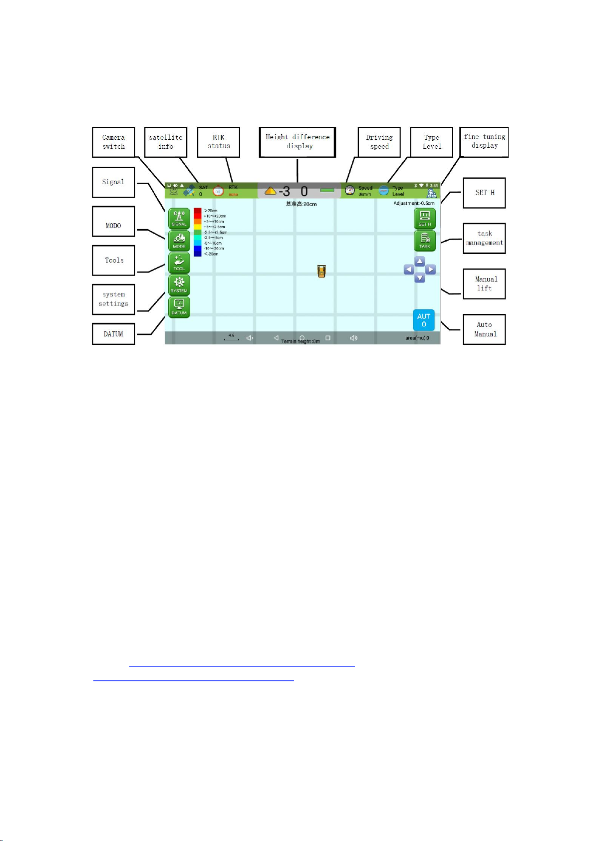
List of main instruments:
name
Terminal
GNSS
antenna
Camera
Power
cable
Main
cable
GNSS
cable
Camera
adapter
cable
RAM
bracket
4G
Antenna
R26
base
PCS
1
2
1
1
1
2
1
1
1
1
Remark
Radio
module
included
The display terminal is mounted at a convenient location for the driver using a RAM bracket.
For tractors without a cab, the instrument should be protected from sun exposure/rain, and
care must be taken to prevent the instrument from falling to the ground or being strongly
impacted by other objects.
·The power must be cut off before installing and disassembling each cable;
·Do not use hard objects when operating the display screen;
·Please connect your device strictly according to the requirements in this manual;
When supplying power, pay attention to the equipment power supply requirements (DC12V);
·Pay attention to take appropriate lightning protection measures to prevent lightning strikes;
The equipment is damaged due to force measure (lightning strike, high voltage, collision, etc.),
which is not within the scope of free maintenance of the company;
·It is forbidden to disassemble the product by yourself, otherwise the warranty will not be
granted;
·When using this system, it should be in an open field far away from the shelter;
·Please stay away from interference sources such as strong electric fields, magnetic fields,
high-voltage lines, and radio signal towers during use of the device.

2
System connection diagram:
①: Display terminal: fixed at the convenient operation position of the cab;
②: GNSS cable: connect the display terminal to the GNSS antenna;
③: 4G antenna: connected to the display terminal;
④: GNSS antenna: connected to the display terminal through the antenna cable, fixed
at a suitable position on the left side of the shovel body;
⑤: GNSS antenna: connected to the display terminal through the antenna cable, fixed
at a suitable position on the right side of the shovel body;
⑥: Communication main cable: connect the display terminal and other interfaces;
⑦: Camera extension cable, connecting the display terminal and the camera;
⑧: On-board camera, real-time monitoring of shovel status
⑨: Power cord: directly connected to the 12V battery, pay attention to the positive
and negative poles to prevent reverse connection;

3
Job display information:
Job operation process:
1. Set up a mobile base station (the network base station ignores this step);
2. Check whether the instrument is firmly fixed;
3. Check whether the cable is connected correctly;
4. Set the working datum:
a. Start the bulldozer;
b. Turn on the system power switch and start the level ground guidance software;
c. Click "SYSTEM to select a suitable base station;
d. Select "TASK" - "New" to create job information; e. Click "MODE" and select
"LEVEL/SLOPE" mode;
5. After setting the leveling mode, click "AUTO" to start the operation;
6. Drive the bulldozer for guided leveling work.
Latest software download link:
https://www.dropbox.com/sh/shv8twous76ja51/
AACMkxQJwI8yOZGB1GUkewEPa?dl=0

4
Common situation:
1. The bulldozing shovel cannot continue to push the soil during leveling: click the "SET
H" - "↓" icon to set the base level down by 3~5cm;
2. During leveling, the bulldozing blade continues to push the soil without unloading:
click the "SET H" - "↑" icon, and set the base level to adjust by 3~5cm;
3. Occasionally, the bulldozer blade pushes too much soil during leveling: in automatic
state,
manually control the lifting of the bulldozer blade;
4. Re-adjust the datum level during leveling: adjust the height of the bulldozer blade,
click "SET H" - "BASE" - "COMFIRM";
Common exceptions:
1. There is no response when the system power switch is turned on: Check the power
cord, insurance, and battery power;
2. The base station signal is abnormal: click "SIGNAL" - "CORS" - Log in to the CORS
account again
Equipment main parameters:
Name: Beidou satellite grader
Signal tracking number: Beidou, GPS, GLONASS
RTK Accuracy: ±(20+1×10⁻⁶×D) mm
Base station selection: network/radio station/CORS
Protection level: IP67 dustproof and waterproof (display terminal)
Display indication: 10-inch touch screen
Working temperature: -20℃~+65℃
Working voltage: DC12V
Tablet size: 281mm×181mm×42mm
Weight: about 4Kg (system)

5
1. Base station selection:
a. First check the RTK status, if it is displayed as "single", then select the base station;
b. SIGNAL -- CORS -- Log in to your CROS account.
c. After connecting to the base station, check whether the RTK status is "Fixed", and the
reference display is a digital non-text prompt;
2. New job information:
TASK -- NEW -- CREATE ; (or click "CREATE" directly after starting the software)

6
3. Set base height (horizontal mode):
a. Manually adjust the bulldozing blade to a position 5~10cm away from the ground;
b. MODE -- LEVEL -- H Lock -- SURE
C. MODE -- LEVEL -- H System -- SURE

7
4. Slope mode (Two-point mode -- Heading mode -- Double mode)
a. MODE -- SLOPE -- Two-point mode -- Collect point A -- Collect point B -- FINISH -- AUTO

8
b. MODE -- SLOPE -- Heading mode -- Collect point A -- Collect point B -- FINISH -- AUTO
c. MODE -- SLOPE -- Double mode -- Collect point A -- Collect point B --
Collect point c -- FINISH -- AUTO

9
5. SET T
a. The bulldozing shovel cannot continue to push the soil during leveling: click the
"Baseline Setting" - "↓" icon to set the base level down by 3~5cm;
b. When leveling, the bulldozing blade continues to push the soil without unloading:
click the "Baseline Setting" - "↑" icon, and set the base level to be adjusted by
3~5cm.
6. Blade width (SYSTEM--Other)

10
7. Driving status(SYSTEM--Other--Tick”display driving status”),real-time
display of driving status.
8. Localization map (After the job is completed, start the software again to
load the last job track).
9. ALL display track (After the job is completed, start the software again to
load the last job track)
Table of contents
Other SMAJAYU Farm Equipment manuals