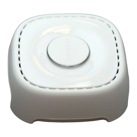
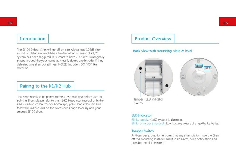
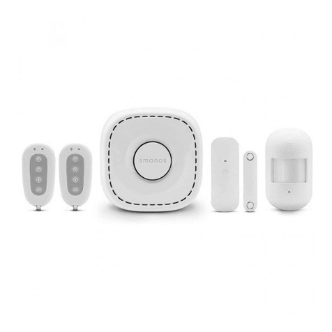
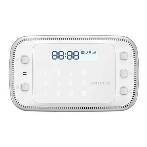
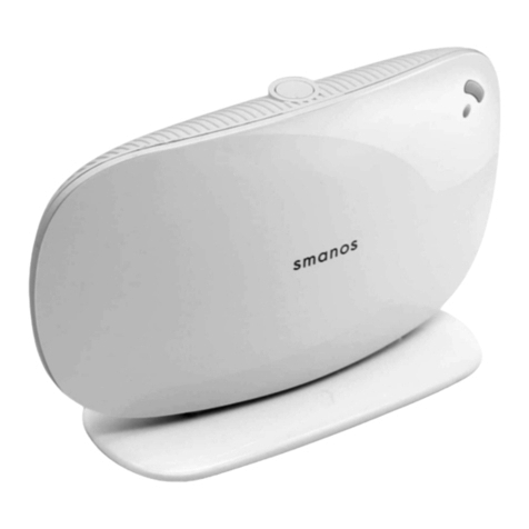
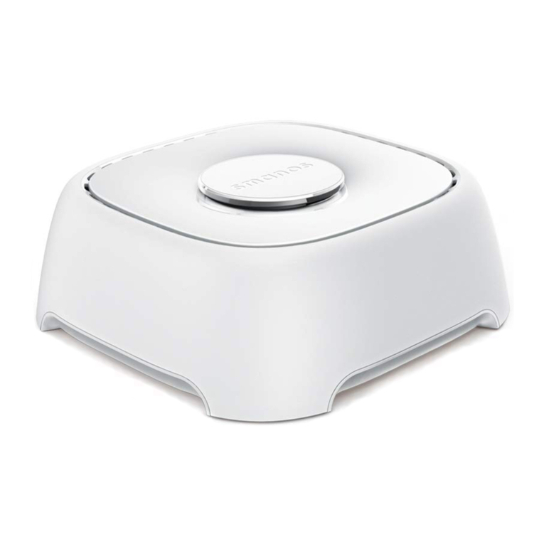
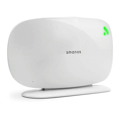
Smanos X300 User manual

Printed in China
PA: X300-UM-EN/DE/FR/NL-V1.0
SMANOS HOLDING LTD. All Rights Reserved.
C
GSM/SMS
X300
Alarm System
User Mannual
Multilingual User Manual
EN
FREN DE NL

Testing -------------------------------------------------------------------------
Please read this user manual carefully .
Please kindly keep this user manual for your reference when necessary.
Table of Contents
Foreword -----------------------------------------------------------------------
Safety Precautions -------------------------------------------------------------
Control Panel and Accessories ------------------------------------------------
Battery and AC Adapter -------------------------------------------------------
Features ------------------------------------------------------------------------
Package List ---------------------------------------------------------------
Test and Install the Control Panel -----------------------------------------
Overview ---------------------------------------------------------------------
Insert the SIM Card -----------------------------------------------------------
Remove the SIM Card --------------------------------------------------------
Install the Control Panel ------------------------------------------------------
Test and Install Accessories -----------------------------------------------
1.Remote Control ---------------------------------------------------------
Overview --------------------------------------------------------------------
Arm -------------------------------------------------------------------------
Disarm ----------------------------------------------------------------------
Home mode ----------------------------------------------------------------
SOS -------------------------------------------------------------------------
2.Test and Install the Door/Window Contact ------------------------------
Overview --------------------------------------------------------------------
Test the door/window contact -----------------------------------------------
3.Test and install the PIR motion detector ---------------------------------
Overview -------------------------------------------------------------------
Working mode -------------------------------------------------------------
Test the PIR motion detector ------------------------------------------------
Install the PIR motion detector -----------------------------------------------
Installation notices ----------------------------------------------------------
Working Principle -------------------------------------------------------------
01
01
01
02
02
05
06
08
10
10
11
12
12
13
13
14
15
16
17
18
19
20
21
23
25
03~04
06~10
11~24
Mute operation --------------------------------------------------------------
Install the door/window contact ---------------------------------------------
Connect/Delete Accessories ----------------------------------------------
06~28
18~21
15~17
11~14
25~28
Connect the remote control -------------------------------------------------
EN
X300 Alarm app

Connect the door/window contact --------------------------------------------
Connect the PIR motion detector ---------------------------------------------
Connect a wireless siren (optional) --------------------------------------------
Connect other accessories (optional) ------------------------------------------
Delete accessories --------------------------------------------------------------
Arm & Disarm by Free Phone Call ---------------------------------------------
Disarm ------------------------------------------------------------------------
Arm --------------------------------------------------------------------------
SMS Operation -------------------------------------------------------------
Query for menu ---------------------------------------------------------------
Disarm ------------------------------------------------------------------------
Arm -------------------------------------------------------------------------------
Monitor -----------------------------------------------------------------------
Store alarm phone numbers --------------------------------------------------
Change zone name --------------------------------------------------------------
Set siren volume and ringing time --------------------------------------------
Delete wireless detectors -------------------------------------------------------
Delete remote controls -------------------------------------------------------
Switch to testing mode -------------------------------------------------------
SMS alert for low battery -----------------------------------------------------
SMS alert for power failure and restoration ------------------------------------
SMS alert for tamper protection -----------------------------------------------
App Operation ------------------------------------------------------------
Delete wireless siren ----------------------------------------------------------
26
27
27
28
28
28
29
29
29
30
31
31
32
32
34
36
37
39
39
40
40
41
41
42
43
44
45
46
47
48
50
51
53
30~41
Set entry and exit delay time ---------------------------------------------------
Download and Install App ----------------------------------------------------
Add accounts ------------------------------------------------------------
Disarm -------------------------------------------------------------------
Function Setting ---------------------------------------------------------------
Command List ---------------------------------------------------------------------
Store alarm phone numbers -----------------------------------------------------
Change zone name----------------------------------------------------------------
Set entry and exit delay time -----------------------------------------------------
Set siren volume and ringing time ------------------------------------------------
Emergency Call ---------------------------------------------------------------------
Record Alarm Message ------------------------------------------------------------
Restore to Factory Settings --------------------------------------------------------
Zone Mode -------------------------------------------------------------------------
SMS Command List ---------------------------------------------------------------
Command List for Phone Remote Control ----------------------------------------
Arm --------------------------------------------------------------------------
Monitor ------------------------------------------------------------------
Select system language ----------------------------------------------------
42~54
Troubleshooting ----------------------------------------------------------------
Maintenance -----------------------------------------------------------------------
Specifications ------------------------------------------------------------------- 61-62
55
55
55
56
57
57
57
60
29~54
58-59
EN

01 02
Foreword
Dear Customers:
Thank you for choosing our product. This product is a totally D.I.Y. wireless home
security solution. It features automatic connection to various accessories, putting your
home under all-round protection.
To experience this wonderful product, please follow the instructions in the user
manual. If there is any problem when using the product, please contact us for help.
Please read the following precautions carefully; otherwise, damage or affection may
occur to the product.
Safety Precautions
1. Use the product properly
Read and follow the instructions in the user manual.
2. Do not allow liquids or foreign objects to enter the product
Keep it dry because it is not water-proof. If liquid or foreign objects enter the
product, power off the product and unload the battery.
3. Maintain the product property
Do not disassemble or modify the product, unless otherwise stated. Only professionals
can maintain the product.
4. Use original accessories
Use only the accessories authorized by us, We are not liable for any damage/accident
(battery leakage, fire) caused by non-original accessories.
5. Avoid using or storing the device in the following cases
Avoid direct sunlight, temperature higher than 55°C, moisture, dust. Otherwise,
battery leakage, overheat, explosion, fire, burning, or other damages may occur. High
temperature may lead to housing deformation.
Control Panel and Accessories
1. Use only built-in or recommended batteries.
2. Do not throw batteries into fire or expose to high temperature.
3. Do not throw batteries into water or other liquids.
4. Do not short circuit, disassemble, modify or heat batteries.
5. Avoid dropping batteries or subject it to strong impact; otherwise battery leakage,
explosion, fire, damage to the environment may occur.
6. If any part of your body or clothing comes into contact with battery liquid, wash it with
plenty of water.
7. Do not cut, damage, modify power cables, or place weights on power cables.
8. Periodically clean the plug and power outlet.
9. Do not touch the power cable with wet hands, which may result in electric shock or
fire.
10. Do not allow dirt or metal objects (such as pins, keys) come into contact with
the power adapter, which may cause electric shock, fire or other damage.
Battery and AC Adapter
Features
1. Elegant appearance
Streamline design with pure white color
2. Powerful
Support entry and exit delay
Support 5 alarm phone numbers
Support 10 remote controls, 50
wireless accessories
Built-in 18650 3.7V 1200 mAh
lithium battery for 15-hour standby
3. High reliability
Built-in 1,000,000 RF codes
combination
Built-in 105 dB siren
4. User-oriented
Delete accessories by type
Play voice message first when
alarm call is picked up
Phone remote control
Monitor the site
5. Easy to use
Interact by SMS or App
Arm & disarm by free phone call
EN

04
Package List
Please check whether the package contains the following items. If not, please contact
the retailer.
X300 Control Panel x 1
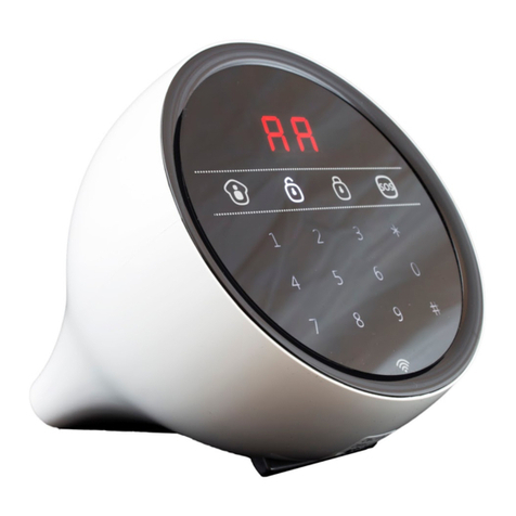
X300 control panel is the "heart and
brain" of the whole system, which is for
receiving and processing the signals
from wireless detectors and remote
controls. In case of emergency, the panel
hoots on site to deter intruders, sent
SMS notification and dials the pre-stored
alarm phone numbers. After user pick
up the phone, system play first the pre-
recorded voice message, then user can
carry out operations such as arm,
disarm, monitor, etc.
MD2300 PIR Motion Detector x 1
The detector adopts digital dual-core fuzzy logic control
processing technology and intelligent analysis
algorithm, effective resolution of interfering signal and
human movement signal, preventing false alarm. It can
detect the temperature and movement of human
bodies within the 8-meter cone space. When detecting
human movement twice in 3 minutes, it switches to the
power-saving mode automatically. After 3 minutes of no
human movement, it switches to the working state.
DS2300 Door/Window Contact x 1
The contact can be used for doors, windows, or other
devices that can be opened or closed. Once a window
or door is opened (the transmitter and magnet are
separated), the control panel will trigger an alarm.
RE2300 Remote Control x 2
It's convenient to carry. With the
remote control, you can
arm/disarm the system, set home
mode, perform mute arm/disarm,
make an emergency call.
Screw for control
panel x 1
Bracket for PIR
detector x 1
Screw kit x 1
(For PIR sensor)
Double-sided tape x 4
(2pcs for door/window contact
2pcs for PIR sensor)
User manual x 1 Warranty card x 1
AC adapter x 1
It provides power supply to the control
panel and built-in battery. When the
power is off, the built-in 18650 lithium
3.7V 1200mAh lithium battery will
sustain 15 hours standby.
03
EN

Overview
06
The control panel, core of the system, can be connected to different detectors. After
you install corresponding detectors in desired locations, if the intrusion is detected, a
detector sends a signal to the control panel, which generates audible alarm or sounds
sirens to deter intruders. Meanwhile, the control panel will send SMS to or call you via
the SIM card. Detectors, such as PIR detector, door/window contacts, vibration
detectors, smoke detector, gas leakage detector, water flood detector, work with the
control panel to shield your family and property.
Working Principle Testing
You need to test the control panel and accessories before installation. This is to ensure
the system works normally.
Test and Install the Control Panel
Front
Bracket
Power LED
Status/Network LED
Mode LED
LED indication:
On: Normal power supply
Flashes once every second: Low voltage
Flashes 5 times every second:
No AC power supply
Power LED/green
On : Arm
Flashes once every second:
Home mode
Off : Disarm
Mode LED/blue
Network LED/blue
Flashes once every 1 second:
No SIM card or searching network
Flash once every 3 seconds:
Normal network
On: Enter connect state
Flashes 5 times every second:
Recording, accessory triggering signals,
sending/receiving SMS, arm/disarm through
remote control
Flashes once every second: Alarming
Status LED/red
sos
05
EN

SIM
08
Insert the SIM Card
Insert the SIM card into the control panel so that the system can work properly.
① Insert the SIM card
② Connect to the power supply
Back
SOS
Alarm Speaker
Audio Speaker
Bottom
07
OFF-ON
POWER
12V/0.5A
SIM
Connect Button
Power On/Off
SIM Card Slot
Service
Power Input
Monitor/MIC
OFF-ON
POWER
12V/0.5A
SIM
EN

10
③ Power on the control panel
Slide the switch on the bottom of the control panel from OFF to ON.
④ Testing succeeds
If the network LED flashes once every 1 second, it indicates searching the network. 10
seconds later, the network LED flashes once every 3 seconds, it indicates the testing
succeeds.
Note: In daily use, it is recommended to use AC power supply. The built-in rechargeable
battery should be used only in the case of no AC power.
A GSM SIM card with normal functions (calling, answering, SMS and caller ID display) is
required.
Insert the SIM card only after the control panel is switched off (Slide the switch from ON to
OFF). Then, switch on the control panel so as to search signals.
If no SIM card is inserted, you can neither receive alarm notification by SMS or phone call, nor
setting the control panel by phone. However, other functions are not affected.
The volume of built-in siren reaches 105 dB. To enhance deterring effect, you can add strobe
sirens.
After the previous testing and the control panel works properly, you can start to install it.
After all setup is completed, attach the control panel to the stand according to the
notch. Secure screws. Then, you can place the control panel on the desk. It is
recommended to enable the tamper protection after installation and all the system
setting are done.
Remove the SIM Card
Switch the control panel (from ON to OFF). Push the SIM card to eject it.
Install the Control Panel
Note: Try to place the control panel in the center of the system or open area for optimal
performance. Avoid load-bearing walls or home appliances that may cause signal attenuation.
TAMPER
OFF-ON
SIM
09
OFF-ON
POWER
12V/0.5A
SIM
OFF-ON
POWER
12V/0.5A
OFF-ON
POWER
12V/0.5A
EN

LED Indicator
Arm
Disarm
Stay
SOS
12
Test and Install Accessories
Accessories in this kit can work only with its own control panels.
Remote Control
RE2300 remote control is dainty and delicate, easy to carry. It can be attached to your
key ring, or just put into your pockets or purses. When you are about to exit or entry
the house, you can use it to arm or disarm the system. In case of any emergency, just
press the button, the alarm will be activated immediately.[SOS]
Overview
+ LED flashes once: Armed or in home mode
× LED flashes once: Disarmed
+, × LEDs flashes once: SOS
LED indication
Arm(Away arm)
In arm state, the system will trigger an
alarm when detecting intrusion.
Press the button. The control [Arm ]
panel beeps once and the mode LED is
on, indicating the system is in the arm
state.
Note: If you do not want to take the remote control, entry and exit delay can be set. For
related definition and setting, please refer to page 36 or 52.
If a wireless keypad is used, you only need to enter the password on the keypad without using
the remote control.
Disarm
In disarm state, the detectors (except
those accessories in the 24-hour zone)
will not trigger an alarm when detecting
intrusion.
Press the button. The [Disarm ]
control panel beeps twice and the mode
LED is off, indicating the system is in
disarm state.
Note: If entry and exit delay is set, you can enter your home directly in the arm state, then
disarm the system within the delay time. No alarm will be triggered in this case. If you disarm
the system after the delay time, the system will trigger an alarm.
Guide Point For The Blind
Metal Ring
11
EN

14
Home mode(Part arm)
In home mode, detectors setting to
home zone are in disarm state; the other
detectors are still in arm state. That is,
you can move freely in the home zone;
however, the rest areas are still being
protected.
Press the button. 3 seconds [Stay ]
later, the control panel beeps once and
the mode LED is on.
Note: The PIR detector is set to home zone by default. That is, the PIR detector will not trigger
an alarm after you press the button.[Stay ]
The zones include home zone, normal zone, 24-hour zone. For details of each zone, please
refer to page 56.
SOS
In case of emergency, you can press the
[SOS] button.
Whenever you press the button on [SOS]
the remote control, the system will alarm
immediately. The control panel will send
SMS with the content "Emergency call" to
user and call the pre-stored phone
numbers.
Mute operation
You can arm and disarm the system silently.
Press the button for 1 second, and then press the button within 3 [Stay ] [Arm ]
seconds. The system is armed silently.
Press the button for 1 second, and then press the button within [Stay ] [Disarm ]
3 seconds. The system is disarmed silently.
Note: If wireless strobe sirens are used, they will not sound either.
13
EN

12
Transmitter
Tamper Switch
LED Indicator
Magnet
Front side Back side
16
Test and Install the Door/Window Contact
The contact contains a transmitter and a magnet, which can be mounted on a door,
window, or any object that can be opened or closed. When the transmitter and
magnet are separated, the contact will send a signal to the control panel and the
control panel will trigger an alarm. The tamper switch ensures that sabotage attempts
to disassemble the contact will trigger an alarm.
Overview
LED indication
Flash once: Intruder is detected.
Flash once per 3 seconds after triggered: Low battery. Replace the battery as soon as
possible.
PCB layout
Test the door/window contact
This is to test whether the contact can work properly.
Remove the insulating strip
The contact works immediately.
Pay attention to the direction
There are triangle marks on the
side of the transmitter and
magnet. Make sure the triangle
marks is close to each other and
within the range of 1 cm.
Test the door/window contact
Press the button. The system switches to the arm state. Separate the transmitter [Arm ]
and magnet with the space more than 2 cm. The red LED on the transmitter is on. Then,
the control panel triggers an alarm. This means the contact works properly.
Tamper Switch CR2032 Lithium Cell Battery
>2cm
Note: When tamper switch is pressed,
system will alarm immediately.
15
EN

Make sure the contact works properly before installing it. There are triangle marks on
the side of the transmitter and magnet. Make sure the triangle marks is close to each
other and within the range of 1 cm. As long as the space between the transmitter and
magnet is over 2 cm and the LED on the transmitter is on.
Install the door/window contact
Secure the contact with double-sided tapes
Secure the transmitter and magnet on the desired locations with double-sided tapes.
Test Button
Double-sided Tape
Stick Place
Bracket Slot
LED Indicator
18
Test and install the PIR motion detector
The detector adopts digital dual-core fuzzy logic control processing technology and
intelligent analysis algorithm, effective resolution of interfering signal and human
movement signal, preventing false alarm. It features automatic temperature
compensation and resistance to flow technology, adapting to environmental and
temperature change. It can detect human movement within the 8-meter cone space,
suitable for halls, hallways, etc.
Overview
LED indication
Flash continuously: Self-testing.
Flash once: Intrusion is detected.
Flash twice: 3 minutes testing mode is finished, enters power saving mode.
Flash once per 3 seconds: Low battery indication, user will receive SMS notification if
detector was connected with panel, please change the batteries immediately.
PCB layout
LED Indicator
Tamper Switch Infrared Sensor
Detection
Lens
Note: If this product is installed on metal door, place
spacers under the transmitter and magnet.
This product is not suitable for shutter door, please
purchase shutter door sensor for your use.
Note: When tamper switch is
triggered, system will enter
alarm state.
17
EN

The product features power-saving
design. If the detector detects human
movement twice in 3 minutes, it will
switch to the sleeping state to save
power. At this time, the LED will not
flash and no alarm. After no
movement within the next 3 minutes,
the detector switches back to the
working state automatically.
Sleep after
detecting human
movement twice
Working mode
Testing mode
After self-testing, press the test
button, the detector switches to
the testing mode and detects
once every 10 seconds. It triggers
an alarm. After 3 minutes, the
LED flashes twice, and the
detector switches to the power
saving mode.
Power Saving mode
Note: After the detector is in the sleeping state, ensure no human movement within 3
minutes; otherwise, the detector remains sleeping.
In the sleeping state, it is recommended that you leave the room after arming the system.
Ensure no human movement in 3 minutes. Then, go into the room, the system alarms
immediately.
Case 2: Press
the test button
and then arm.
Case 1:
Initial start
and then arm.
3 minutes later
No human movement
within 3 minutes
Switch from
sleep to arm.
1. Remove the insulating strip
Remove the insulating strip.
2. Arm the system
Press the button on the [Arm ]
remote control. The system is armed.
3. Trigger an alarm
Keep pressing the test button at the back until the control panel sounds. It indicates
that the PIR motion detector is connected to the control panel.
20
Test the PIR motion detector
This is to test whether the PIR detector works normally.
19
EN

Install the PIR motion detector
For installation notices, please see page 23.
1. Choose a suitable installation location
12
After making sure the detector works normally, do as follows:
2. Fix the detector
Fix the installation bracket on the wall with screws, and then fit the groove at the back
of the detector on the bracket. For the detector of this model, you can stick it at the
corner with double-sided tapes.
2m
3. Test the PIR motion detector
4. Adjust the angle
22
Press the test button at the back. It switches to the testing mode and sustains for 3
minutes. Walk in the detection scope and observe the LED. When human movement is
detected, the LED flashes once.
Adjust the bracket angle to achieve the best detection effect.
Side view Top view
21
EN

Installation notices
It is recommended to mount it at the height of 2m from the ground. The detector aims
at preventing intrusion. Detecting human movement at the entry or exit is critical for
security.
The installation angle affects
sensitivity directly. The sensitivity is
optimal when the walk direction is
vertical to the infrared direction.
Choose the best location and angle
according to the actual situation
and detection scope diagram.
Pay attention to the following during installation:
1. Mount the detector to a location close to the entry or exit
2. Mount the detector in a proper angle
3. Avoid facing to glass windows or doors
5. Avoid facing to swinging objects
4. Avoid facing to or positioning close to
heat/cold sources
Strong light interferes with detection
sensitivity. In addition, complicated
situations, such as traffic flow, stream of
people, also should be avoided.
Swinging objects may also trigger false
triggering. Besides, if there are two
detectors covering the save scope, adjust
the locations to prevent cross-interference.
24
Heat/cold sources, such as heat extraction
units, heaters, air conditioner, microwave
oven, refrigerator, which may cause false
triggering, should be avoided.
ON
23
EN

>2cm
Connect/Delete Accessories
Accessories need to be connected to the control panel so that it can receive signals
from accessories and sound the alarm. Accessories in this kit have been connected to
the control panel before delivery, and ready for use. If the control panel does not
trigger alarms, reconnect them. Accessories purchased separately must be connected
to the control panel before use.
Connect the remote control
This is to connect the remote control to the control panel.
1. Press the connect button on the control panel
Press the button at the [Connect ]
bottom of the control panel with a
sharp object. It beeps once and the
status LED is on.
It beeps once, indicating successful
connection.
2. Press any button on the remote control
25
Note: If the control panel beeps twice, it indicates the remote control has been connected before.
This is to connect the door/window contact to the control panel.
Separate the transmitter and magnet
with the space more than 2 cm. The
control panel beeps once, indicating
successful connection.
1. Put the transmitter and magnet together
3. Separate the transmitter and magnet
Press the button at the [Connect ]
bottom of the control panel with a
sharp object. It beeps once and the
status LED is on.
26
Connect the door/window contact
Make sure the triangle marks is close to each other and within the range of 1 cm.
2. Press the connect button on the control panel
Note: If the control panel beeps twice, it indicates the door/window contact has been
connected before.
OFF-ON
POWER
12V/0.5A
OFF-ON
POWER
12V/0.5A
EN

Connect the PIR motion detector
Press the test button at the back of
the PIR motion detector twice. The
control panel beeps once, indicating
successful connection.
This is to connect the PIR motion detector to the control panel.
Press the button at [Connect ]
the bottom of the control panel
with a sharp object. It beeps once
and the status LED is on.
1. Press the connect button on the control panel
2. Press the test button on the PIR
motion detector
Connect a wireless siren (Optional)
This is to connect a wireless siren to the control panel.
The siren beeps once, indicating successful
connection.
27
Note: If the control panel beeps twice, it indicates the detector has been connected before.
1. Make the siren in connect state (Take SS1005 for example)
2. Press the [SOS] button on the control panel
Press the connect button in wireless
siren, the siren beeps once. 3 seconds
later, the siren beeps again. The LED
flashes every 1 second, which means
the siren is in connect state.
Connect other accessories (optional)
Delete accessories
Delete wireless siren
Press the button at the [Connect ]
bottom of the control panel for more
than 5 seconds with a sharp object. The
control panel beeps once, indicating all
accessories are deleted.
Deleting accessories is to disconnect accessories from the control panel. After that, the
control panel cannot receive signals from accessories.
28
For how to connect other accessories to the control panel, please refer to related user
manuals or operations on the PIR motion detector and door/window contact.
Delete the connection between wireless siren and control panel.
Press and hold the connect button of the wireless siren until one beep is heard, which
means the deletion is succeeded.
OFF-ON
POWER
12V/0.5A
SOS
Note: If the siren beeps twice, it indicated
the siren and the panel has been connected
before. To connect other wireless siren,
please refer to the related manuals.
OFF-ON
POWER
12V/0.5A
EN

Function Setting
Arm & Disarm by Free Phone Call
You can set the system by phone call, SMS, App, operations on the control panel, thus
putting your home under protection.
Insert the SIM card only after the control panel is switched off (from ON to OFF). Then,
switch on the control panel (from OFF to ON) so as to search signals. A GSM SIM card
with normal functions (calling, answering, SMS and caller display) is required.
You can make a call to arm or disarm the system remotely for free.
Call the phone number of the control panel. Hold on until the control panel hangs up
the call. The control panel will not call back. The system is disarmed.
Disarm
Arm
You can make a call to arm the system.
Call the phone number of the control panel. Hang up when hearing the ring tone. The
control panel will call back. Hang up the phone directly. The system is armed.
29
Note: In the initial state, any number can call to arm or disarm the system. After alarm phone
numbers are stored, only these numbers can call to disarm or arm the system. Other
numbers will be blocked out automatically by the control panel for security. The system is
disarmed by default.
You can make a call to disarm the system.
SMS Operation
You can operate the system by sending SMS. SMS is charged according to telecom
operator.
Query for menu
This is to query for the menu.
1. Send "?"
Send the SMS to the phone number of the control panel. "?"
2. The system replies with a menu
After the control panel receives the SMS, the status LED flashes quickly. The control
panel replies with the following menu.
30
?
‘0’Disarm
‘1’Arm
‘2’Call-back monitor
‘3’Store phone number
‘41-49’Change zone name
‘5’Entry and exit delay
‘6’Set siren volume and ringing time
EN

Disarm
This is to disarm the system.
1. Send "0"
Send the SMS to the phone number of the control panel."0"
After the control panel receives the SMS, the status LED flashes quickly and then the
mode LED is off. The system is disarmed. The control panel replies SMS to your smart
phone with the content: System disarmed.
2. Disarm the system
31
Arm
1. Send "1"
Send the SMS to the phone number of the control panel."1"
After the control panel receives the SMS, the status LED flashes quickly and then the
mode LED is on. The system is armed. The control panel replies SMS to your smart
phone with the content: System armed.
2. Arm the system
This is to arm the system.
32
0
System disarmed.
1
System armed.
2. Monitor the site
After the control panel receives the SMS, the status LED flashes quickly. The control
panel calls your phone number. Then, you can answer the call and monitor (listen in)
the site.
Monitor
This is to monitor the site remotely by call-back from the control panel.
1. Send "2"
Send the SMS to the phone number of the control panel."2"
2
Store alarm phone numbers
1. Send "3"
You can store 5 alarm phone numbers by SMS. When an alarm is triggered, the control
panel will send SMS to the stored alarm phone numbers in turn, and then call these
numbers in turn. After the control panel receives an alarm signal, it takes about 15
seconds to send the first SMS. (The time may differ from network signal strength.)
Send the SMS to the phone number of the control panel."3"
3
EN

3. Forward and edit the SMS
4. The control panel replies with SMS
After receiving the SMS, forward and edit it. Edit the alarm phone numbers and send
the SMS back.
The control panel replies SMS to your smart phone with the content:Store phone
numbers successfully.
33
Note: If the input format or content is incorrect, the control panel replies: Wrong input!
After you store alarm phone numbers, the control panel accepts only the commands from
these numbers. If a number rather than the 5 alarm phone numbers sends SMS to operate
the control panel, it replies: Sorry, operation failed. Phone number is not authorized.
Once an alarm is triggered, the control panel will call these numbers for three rounds at
most. As long as one user answers the call and operates the system, the control panel stops
dialing the next number.
Change zone name
1. Send "41"-"49"
You can change the name of the first 9 zones, facilitating zone identification. Send "41"
to change the name of the first zone; send "42" to change the name of the second
zone, and so on. You can change only the first 9 zones. Remote controls do not
involve zones.
Send the SMS to the phone number of the control panel."41"-"49"
2. The control panel replies with SMS
After the control panel receives the SMS, the status LED flashes quickly. The control
panel replies SMS to your smart phone.
TEL:
1. 6800001
2. 6800002
3. 6800003
4.
5.
Store phone numbers successfully.
41
Zone 1 Name:
Zone 1 Alarm
2. The control panel replies with SMS
After the control panel receives the SMS, the status LED flashes quickly. The control
panel replies SMS to your smart phone.
TEL:
1.
2.
3.
4.
5.
34
EN
Other manuals for X300
3
Table of contents
Other Smanos Security System manuals
Popular Security System manuals by other brands

Videofied
Videofied XT GPRS installation manual

Draytek
Draytek Vigor3900 Series user guide

Xtralis
Xtralis ADPRO PRO E installation guide

Panasonic
Panasonic Fire Alarm Systems Heat Detectors 6275 Specification sheet

Paso
Paso C57/6-EN instruction sheet

Federal Signal VAMA
Federal Signal VAMA AS-422/6S Installation and operating instructions

Federal Signal Corporation
Federal Signal Corporation 400HMK-AC instruction sheet

Protector Security Group
Protector Security Group The Protector owner's manual

Inner Range
Inner Range CONCEPT IQ. PLUS Programmer's manual

Tyco
Tyco WMA-1 manual

Ingersoll-Rand
Ingersoll-Rand VON DUPRIN 33 Series installation instructions

Signet
Signet FMIC manual