SMAR ld301 Manual

INTELLIGENT PRESSURE TRANSMITTER
WITH CONTROL CAPABILITY
OPERATION AND MAINTENANCE
INSTRUCTION / MANUAL
LD301
VERSION 6
LD301ME
JAN / 03

web: www.smar.com
smar Specifications and information are subject to change without notice.
For the latest updates, please visit the SMAR website above.
BRAZIL
Smar Equipamentos Ind. Ltda.
Rua Dr. Antonio Furlan Jr., 1028
Sertãozinho SP 14170-480
Tel.: +55 16 645-3599
Fax: +55 16 645-6454
e-mail: dncom@smar.com.br
ARGENTINA
Smar Argentina
Soldado de La Independencia, 1259
(1429) Capital Federal – Argentina
Telefax: 00 (5411) 4776 -1300 / 3131
e-mail: smarinfo@smarperifericos.com
CHINA
Smar China Corp.
3 Baishiqiao Road, Suite 30233
Beijing 100873, P.R.C.
Tel.: +86 10 6849-8643
Fax: +86-10-6894-0898
e-mail: [email protected]
FRANCE
Smar France S. A. R. L.
42, rue du Pavé des Gardes
F-92370 Chaville
Tel.: +33 1 41 15-0220
Fax: +33 1 41 15-0219
e-mail: sm[email protected]r
GERMANY
Smar GmbH
Rheingaustrasse 9
55545 Bad Kreuznach
Germany
Tel: + 49 671-794680
Fax: + 49 671-7946829
e-mail: [email protected]
MEXICO
Smar México
Cerro de las Campanas #3 desp 119
Col. San Andrés Atenco
Tlalnepantla Edo. Del Méx - C.P. 54040
Tel.: +53 78 46 00 al 02
Fax: +53 78 46 03
e-mail: vent[email protected]
SINGAPORE
Smar Singapore Pte. Ltd.
315 Outram Road
#06-07, Tan Boon Liat Building
Singapore 169074
Tel.: +65 6324-0182
Fax: +65 6324-0183
e-mail: [email protected]
MIDDLE EAST
Smar Middle East
Al Sadaka Tower, Suite 204
P.O. Box 268
Abu Dhabi
Tel: 9712-6763163 / 6760500
Fax: 9712-6762923
e-mail: sm[email protected].ae
USA
Smar International Corporation
6001 Stonington Street, Suite 100
Houston, TX 77040
Tel.: +1 713 849-2021
Fax: +1 713 849-2022
e-mail: [email protected]om
Smar Laboratories Corporation
10960 Millridge North, Suite 107
Houston, TX 77070
Tel.: +1 281 807-1501
Fax: +1 281 807-1506
e-mail: sm[email protected]
Smar Research Corporation
4250 Veterans Memorial Hwy.
Suite 156
Holbrook , NY 11741
Tel: +1-631-737-3111
Fax: +1-631-737-3892
e-mail: sales@smarresearch.com

Introduction
III
INTRODUCTION
The LD301 is a smart pressure transmitter for differential, absolute, gauge, level and flow measurements.
It is based on a field-proven capacitive sensor that provides reliable operation and high performance. The
digital technology used in the LD301 enables the choice of several types of transfer functions, an easy
interface between the field and the control room and several interesting features that considerably reduce
the installation, operation and maintenance costs.
The LD301, besides the normal functions offered by other smart transmitters, offers the following
functions:
√
√√
√(∆
∆∆
∆P)3- used for trapezoidal weirs in open channel flow metering.
√
√√
√(
((
(∆
∆∆
∆P)5- used for V-notch weirs in open channel flow metering.
TABLE - the pressure signal is custom linearized according to a 16-point table, enabling, e.g.,
conversion of level to volume of a horizontal cylindrical tank.
CONTROLLER - the Process Variable is compared to a Setpoint. The deviation acts on the
output signal according to a PID algorithm (optional).
LOCAL ADJUSTMENT - not Only for Lower and Upper value, but input/output function,
operation mode, indication, setpoint, PID parameters (optional) as well.
PASSWORD - three levels for different functions.
OPERATION COUNTER - shows the number of changes in each function.
TOTALIZATION - flow totalization into volume or mass.
USER-UNIT - indication in engineering unit of the property actually measured, e.g., level, flow or
volume.
Get the best results of the LD301 by carefully reading these instructions.
Smar’s pressure transmitters are protected by U.S. patents 643379.

LD301 - Operation and Maintenance Instruction Manual
IV
NOTE
This manual is compatible with version 6.XX, where 6 denotes software
version and XX software release. The indication 6.XX means that this
manual is compatible with any release of software version 6.

Index
V
Table of Contents
1 INSTALLATION
GENERAL.............................................................................................................................................................. 1.1
MOUNTING ........................................................................................................................................................... 1.1
ELECTRONIC HOUSING ROTATION ................................................................................................................... 1.3
ELECTRIC WIRING............................................................................................................................................... 1.4
2 OPERATION
FUNCTIONAL DESCRIPTION - SENSOR ............................................................................................................. 2.1
FUNCTIONAL DESCRIPTION - HARDWARE ....................................................................................................... 2.2
FUNCTIONAL DESCRIPTION - SOFTWARE ........................................................................................................ 2.3
THE DISPLAY........................................................................................................................................................ 2.5
3 CONFIGURATION
CONFIGURATION FEATURES ............................................................................................................................. 3.2
MANUFACTURING DATA AND IDENTIFICATION ................................................................................................ 3.2
PRIMARY VARIABLE TRIM - PRESSURE ............................................................................................................ 3.3
PRIMARY VARIABLE CURRENT - TRIM .............................................................................................................. 3.4
ENGINEERING UNIT SELECTION........................................................................................................................ 3.6
TRANSMITTER ADJUSTMENT TO THE WORKING RANG................................................................................. 3.5
TRANSFER FUNCTION FOR FLOW MEASUREMENT......................................................................................... 3.7
TABLE POINTS ..................................................................................................................................................... 3.8
TOTALIZATION CONFIGURATION....................................................................................................................... 3.9
PID CONTROLLER CONFIGURATION ............................................................................................................... 3.10
EQUIPMENT CONFIGURATION ........................................................................................................................ 3.11
EQUIPMENT MAINTENANCE ............................................................................................................................ 3.12
4 PROGRAMMING USING LOCAL ADJUSTMENT
THE MAGNETIC TOOL ......................................................................................................................................... 4.1
SIMPLE LOCAL ADJUST ...................................................................................................................................... 4.2
ZERO AND SPAN RERANGING ........................................................................................................................... 4.2
COMPLETE LOCAL ADJUSTMENT ...................................................................................................................... 4.3
LOCAL PROGRAMMING TREE ............................................................................................................................ 4.3
OPERATION [OPER]............................................................................................................................................. 4.4
TUNING [TUNE] .................................................................................................................................................... 4.5
CONFIGURATION [CONF] .................................................................................................................................... 4.7
RANGE (RANGE) .................................................................................................................................................. 4.8
OPERATION MODE (MODE) .............................................................................................................................. 4.12
TOTALIZATION [TOTAL] ..................................................................................................................................... 4.12
PRESSURE TRIM [TRIM] .................................................................................................................................... 4.13
ESCAPE LOCAL ADJUSTMENT [ESC] ............................................................................................................... 4.15
5 MAINTENANCE PROCEDURES
GENERAL.............................................................................................................................................................. 5.1
DIAGNOSTIC WITH THE CONFIGURATOR ......................................................................................................... 5.1
ERRO MESSAGES............................................................................................................................................... 5.1
DIAGNOSTIC WITH THE TRANSMITTER............................................................................................................. 5.2
DISASSEMBLY PROCEDURE .............................................................................................................................. 5.4
SENSOR................................................................................................................................................................ 5.4
REASSEMBLY PROCEDURE ............................................................................................................................... 5.6
ELECTRONIC CIRCUIT ........................................................................................................................................ 5.7
INTERCHANGEABILITY........................................................................................................................................ 5.8
ACCESSORIES ..................................................................................................................................................... 5.8
SPARE PARTS LIST FOR TRANSMITTER ........................................................................................................... 5.8

LD301 - Operation and Maintenance Instruction Manual
VI
6 TECHNICAL CHARACTERISTICS
FUNCTIONAL SPECIFICATIONS.......................................................................................................................... 6.1
CONFIGURATOR.................................................................................................................................................. 6.3
PERFORMANCE SPECIFICATIONS..................................................................................................................... 6.3
PHYSICAL SPECIFICATIONS............................................................................................................................... 6.4
ORDERING CODE FOR DIFFERENTIAL, MANOMETRIC AND ABSOLUTE TRANSMITTER .............................. 6.6
ORDERING CODE FOR LEVEL TRANSMITTER .................................................................................................. 6.7
APPENDIX
A: CONTROL DRAWING....................................................................................................................................... 6.8

Section 1
1.1
INSTALLATION
GENERAL
The overall accuracy of a flow, level, or pressure measurement depends on several variables. Although
the transmitter has an outstanding performance, proper installation is essential to maximize its
performance.
Among all factors, which may affect transmitter accuracy, environmental conditions are the most
difficult to control. There are, however, ways of reducing the effects of temperature, humidity and
vibration.
The LD301 has a built-in temperature sensor to compensate for temperature variations. At the factory,
each transmitter is submitted to a temperature cycle, and the characteristics under different
temperatures are recorded in the transmitter memory. At the field, this feature minimizes the
temperature variation effect.
Locating the transmitter in areas protected from extreme environmental changes can minimize
temperature fluctuation effects.
In warm environments, the transmitter should be installed to avoid, as much as possible, direct
exposure to the sun. Installation close to lines and vessels subjected to high temperatures should also
be avoided. Use longer sections of impulse piping between tap and transmitter whenever the process
fluid is at high temperatures. Use of sunshades or heat shields to protect the transmitter from external
heat sources should be considered, if necessary.
Humidity is fatal to electronic circuits. In areas subjected to high relative humidity, the O-rings for the
electronic housing covers must be correctly placed and the covers must be completely closed by
tighten them by hand until you feel the O-rings being compressed. Do not use tools to close the covers.
Removal of the electronics cover in the field should be reduced to the minimum necessary, since each
time it is removed; the circuits are exposed to the humidity.
The electronic circuit is protected by a humidity proof coating, but frequent exposures to humidity may
affect the protection provided. It is also important to keep the covers tightened in place. Every time they
are removed, the threads are exposed to corrosion, since painting cannot protect these parts. Code-
approved sealing methods should be employed on conduit entering the transmitter. The unused outlet
connection should be plugged accordingly.
Although the transmitter is virtually insensitive to vibration, installation close to pumps, turbines or other
vibrating equipment should be avoided.
Proper winterization (freeze protection) should be employed to prevent freezing within the measuring
chamber, since this will result in an inoperative transmitter and could even damage the cell.
NOTE:
When installing or storing the level transmitter, the diaphragm must be protected to avoid
scratching-denting or perforation of its surface.
MOUNTING
The transmitter has been designed to be both rugged and lightweight at the same time. This make its
mounting easier mounting positions are shown in Figure 1.1.
Existing standards for the manifolds have also been taken into account, and standard designs fit
perfectly to the transmitter flanges.
Should the process fluid contain solids in suspension, install valves or rod-out fittings at regular
intervals to clean out the pipes.
The pipes should be internally cleaned by using steam or compressed air, or by draining the line with
the process fluid, before such lines are connected to the transmitter (blow-down).

LD301 – Operation and Maintenance Instruction Manual
1.2
ANSI-B 16.5 - DIMENSIONS
pclassA B C D E F G X
150 152.4 120.7 22 1.6 19.1 91.9 48 4
300 165.1 127 22.8 1.6 19.1 91.9 48 82”
600 165.1 127 32.3 6.4 19.1 91.9 48 8
150 190.5 152.4 24.4 1.6 19.1 127 73 4
300 209.5 168.1 29 1.6 22.2 127 73 83”
600 209.5 168.1 38.7 6.4 22.2 127 73 8
150 228.6 190.5 24.4 1.6 19.1 158 96 8
300 254 200 32.2 1.6 22.3 158 96 84”
600 273 215.9 45 6.4 25.4 158 96 8
DIN 2501 / 2526 form D - DIMENSIONS
DN PN A B C D E F G X
50 10/40 165 125 20 3 18 102 48 4
80 10/40 200 160 24 3 18 138 73 8
10/16 220 180 20 3 18 158 96 8
100 25/40 235 190 24 3 22 162 96 8
Fig. 1.1 – Dimensional Drawing and Mounting Position for LD301
Electrical
Connection
Mounting Bracket
Adapter
Allow 150mm minimum for local
zero and span adjustment with
magnetic tool
Level Diaphragm
Screws
Label
Level Diaphragm
with extension
Drain for Vent
1/4 - 18 NPT
Without Adapters
1/2 - 14 NPT
With Adapters
DIMENSIONS
RANGE
F1 - F2 - F3
F4
F6
F5
X
mm
1.71 2.13 2.68
1.77 2.25 2.78
1.75 2.20 2.76
1.79 2.27 2.82
43.5 54.0 68.0
45.0 57.2 70.6
44.5 56.0 70.0
45.5 57.6 71.6
mmin ininmm
YZ
Allow 150mm minimum for local
zero and span adjustment with
magnetic tool
Terminal
Connections
1/4 - 18 NPT
Without Adapters
1/2 - 14 NPT
With Adapters
113
(4,44)
186,5
(7,34)
94
(3,70)
41.3
(1,62)
179
(7,04)
DN-50X
Y
Z
83
( 3,26)
181
(7,12)
97
(3,81)
47,5
(1,87)
72,5
(2,85)
100,5
(3,95)
Electrical
Connection
Terminal
Connections
11 3
(4,44)
182
(7,16)
72,5
(2,85)
100,5
(3,95)
83
( 3,26)
96
(3,78)
83
(3,26)
97
(3,81)
45 máx
(1,77)
D
C
E
B
G
F
A
Drain for Vent

Installation
1.3
Fig. 1.2 – Drawing Mounting of LD301 on the Panel
Observe operating safety rules during wiring, draining or blow-down.
Some examples of installation, illustrating the position of the transmitter in relation to the taps, are
shown in Figure 1.3. The location of pressure taps and the relative position of the transmitter are
indicated in Table 1.1.
Process
Fluid
Location
of Taps
Location of LD301 in
Relation to the Taps
Gas Top or Side Above the Taps
Liquid Side Below the Taps or at the Piping Centerline
Steam Side Below the Taps using Sealing (Condensate) Pots
Table 1.1 - Location of Pressure Taps
NOTE:
Except for dry gases, all impulse lines should slope at the ratio 1:10, in order to avoid trapping
bubbles in the case of liquids, or condensate for steam or wet gases.
ELECTRONIC HOUSING ROTATION
The electronic housing can be rotated in order to better position the digital display. To rotate it, use the
Housing Rotation Set Screw, see Figure 1.4
WARNING: EXPLOSION PROOF INSTALLATIONS
The electronic housing and the sensor assembly in potentially explosive atmospheres must have a
minimum of 6 threads fully engaged. The provided joint allows 1 turn extra. Try to adjust the display
window position by rotating the housing clockwise. If the thread reaches the end before the desired
position, then rotate the housing counterclockwise, but not by more than one turn of the thread end.
Transmitters have a stopper that restricts housing rotation to one turn. See Section 5, Figure 5.1.
The digital display itself can also be rotated. See Section 5, Figure 5.4.
NOTE
The process flange of the level transmitters can be rotated ±45º. To do this just loosens the two screws
(Fig. 1.1) and rotate the flange. Do not take the screws out. There is a label (Fig. 1.1) on the
transmitter with these instructions
PANEL MOUNTING
(See section 5 - spare parts list
for mounting backets available)

LD301 – Operation and Maintenance Instruction Manual
1.4
Fig 1.3 – Position of the Transmitter and Taps
ELECTRIC WIRING
Reach the wiring block by removing the Electrical Connection Cover. This cover can be locked closed
by the cover locking screw (Figure 1.4). To release the cover, rotate the locking screw clockwise.
Fig. 1.4 – Housing Rotating Set Screw
The wiring block has screws on which fork or ring-type terminals can be fastened. See Figure 1.5.
HAZARDOUS AREAS
In hazardous areas with explosion proof requirements, the covers must be tightened with
at least 8 turns. In order to avoid the penetration moisture or corrosive gases, tighten the
O’ring until feeling the O'ring touching the housing. Then, tighten more 1/3 turn (120°) to
guarantee the sealing. Lock the covers using the locking screw.
In hazardous zones with intrinsically safe or nonincendive requirements, the circuit entity
parameters and applicable installation procedures must be observed.
Cable access to wiring connections is obtained by one of the two conduit outlets. Conduit
threads should be sealed by means of code-approved sealing methods. The unused outlet
connection should be plugged and sealed accordingly.
Explosion proof, nonincendive and intrinsic safety Factory Mutual certification are standards
for LD301 (see control drawing in Appendix A).
Should other certifications be necessary, refer to the certification or specific standard for
installation limitations.

Installation
1.5
Fig. 1.5 – Wiring Block
For convenience there are two ground terminals: one inside the cover and one external, located close
to the conduit entries.
Use of twisted pair (22 AWG or greater than) cables is recommended.
Avoid routing signal wiring close to power cables or switching equipment.
The unused outlet connection should be plugged and sealed accordingly.
The LD301 is protected against reverse polarity.
The Figure 1.6 - Conduit Installation Diagram, shows the correct installation of the conduit, in order to
avoid penetration of water, or other substance, which may cause malfunctioning of the equipment.
Figure 1.6 - Conduit Installation Diagram.
CO
RRE
C
T
WIRES
IN
CO
RRE
C
T
LD301 – Operation and Maintenance Instruction Manual
1.6
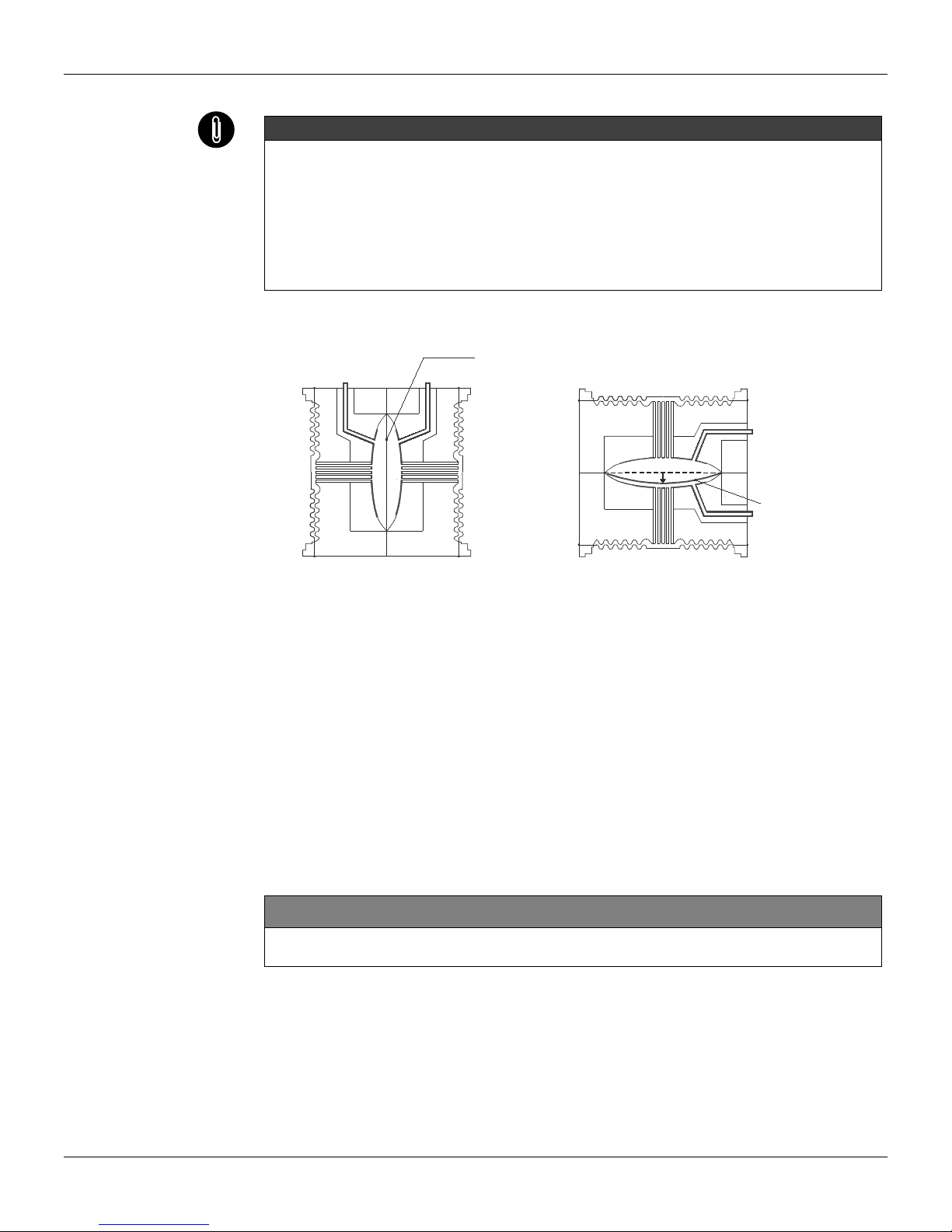
NOTE
The transmitters are calibrated in the vertical position and a different mounting position displaces
the zero point. Consequently, the indicator will indicate a different value from the applied pressure.
In these conditions, it is recommended to do the zero pressure trim. The zero trim is to compensate
the final assembly position and its performance, when the transmitter is in its final position. When
the zero trim is executed, make sure the equalization valve is open and the wet leg levels are
correct.
For the absolute pressure transmitter, the assembly effects correction should be done using the
Lower trim, due to the fact that the absolute zero is the reference for these transmitters, so there
is no need for a zero value for the Lower trim.
When the sensor is in the horizontal position, the weight of the fluid pushes the diaphragm down,
making it necessary a Lower Pressure Trim.
Fig.1.7 - Sensor Positions
Connection of the LD301 working as transmitter should be done as in Figure 1.8.
Connection of the LD301 working as a controller should be as indicated in Figure 1.9.
Connection of the LD301 in multidrop configuration should be done as in Figure 1.10. Note that a
maximum of 15 transmitters can be connected on the same line and that they should be connected in
parallel.
Take care to the power supply as well, when many transmitters are connected on the same line.
The current through the 250 Ohm resistor will be high causing a high voltage drop. Therefore make
sure that the power supply voltage is sufficient.
The Hand-Held Terminal can be connected to the communication terminals of the transmitter or at any
point of the signal line by using the alligator clips. It is also recommended to ground the shield of
shielded cables at only one end. The ungrounded end must be carefully isolated.
NOTE:
Make sure that the transmitter is operating within the operating area as shown on the load curve (Figure 1.11).
Communication requires a minimum load of 250 Ohm.
DIAPHRA
G
M
S
EN
SO
R
SENSOR IN THE VERTICAL POSITION SENSOR IN THE HORIZONTAL POSITION
HEAD OF THE FLUID
DIAPHRAGM SENSO
R

Installation
1.7
Fig. 1.8 – Wiring Diagram for the LD301 Working as a Transmitter
Fig. 1.9 – Wiring Diagram for the LD301 Working as a Controller (Optional)
Fig. 1.10 – Wiring Diagram for the LD301 in Multidrop Configuration
Fig. 1.11 – Load Curve

LD301 – Operation and Maintenance Instruction Manual
1.8

Section 2
2.1
OPERATION
FUNCTIONAL DESCRIPTION – SENSOR
The LD301 Series Intelligent Pressure Transmitters use capacitive sensors (capacitive cells)
as pressure sensing elements, as shown in Figure 2.1.
Fig. 2.1 – Capacitive Cell
Where,
P1and P2are the pressures in chambers H and L
CH= capacitance between the fixed plate on P1side and the sensing diaphragm.
CL= capacitance between the fixed plate on the P2side and the sensing diaphragm.
d = distance between CH and CL fixed plates.
∆
∆∆
∆d= sensing diaphragm's deflection due to the differential pressure ∆P = P1- P2.
Knowing that the capacitance of a capacitor with flat, parallel plates may be expressed as a
function of plate area (A) and distance (d) between the plates as:
Where,
ε
εε
ε
=dielectric constant of the medium between the capacitor's plates.
Should CH and CL be considered as capacitances of flat and parallel plates with identical
areas, then:
However, should the differential pressure (∆P) applied to the capacitive cell not deflect the
sensing diaphragm beyond d/4, it is possible to assume ∆P as proportional to ∆d, that is:
By developing the expression (CL - CH)/(CL + CH), it follows that:
as the distance (d) between the fixed plates CH and CL is constant, it is possible to conclude
that the expression (CL - CH)/(CL + CH) is proportional to ∆d and, therefore, to the differential
pressure to be measured.
Thus it is possible to conclude that the capacitive cell is a pressure sensor formed by two
capacitors whose capacitances vary according to the applied differential pressure.
d
A
C∈
=
dP ∆∆
α
d
d
CHCL
CHCL
P∆
=
+
−
=∆ 2
and dd
A
CL
∆−
∈
=
)2/(
.
dd
A
CH
∆+
∈
=
)2/(
.

LD301- manual de Instruções, Operação e manutenção
2.2
FUNCTIONAL DESCRIPTION - HARDWARE
Refer to the block diagram Figure 2.2. The function of each block is described below.
Oscillator
This oscillator generates a frequency as a function of sensor capacitance.
Signal Isolator
The Control signals from the CPU are transferred through optical couplers, and the signal from
the oscillator is transferred through a transformer.
(CPU) Central Processing Unit and PROM
The CPU is the intelligent portion of the transmitter, being responsible for the management and
operation of all other blocks, linearization and communication.
The program is stored in an external PROM. For temporary storage of data the CPU has an
internal RAM. The data in the RAM is lost, if the power is switched off, however the CPU also
has an internal nonvolatile EEPROM where data that must be retained is stored. Examples of
such data are: calibration, configuration and identification data.
EEPROM
Another EEPROM is located within the sensor assembly. It contains data pertaining to the
sensor's characteristics at different pressures and temperatures. This characterization is done
for each sensor at the factory.
D/A Converter
Converts the digital data from the CPU to an analog signal with 14-bits resolution.
Output
Controls the current in the line feeding the transmitters.
It acts as a variable resistive load whose value depends on the voltage from the D/A
converter.
Modem
This system providers the data exchange between the se serve-master digital communication
. The transmitter demodulates information from the current line, then modulates the relies
sending then over the line. A "1" is represented by 1200 Hz and "0" by 2200 Hz. The frequency
signal is symmetrical and does not affect the DC-level of the 4-20 mA signal.
Power Supply
Power shall be supplied to the transmitter circuit using the signal line (2-wire system). The
transmitter quiescent consumption is 3.6 mA; during operation, consumption may be as high
as 21 mA, depending on the measurement and sensor status.
The ld301, in the transmitter mode, shows failure indication at 3.6 mA if configured for low
signal failure; at 21 mA, if configured for high signal failure; 3.8 mA in the case of low saturation;
20.5 mA in the case of high saturation and measurements proportional to the applied pressure
in the range between 3.8 mA and 20,5 mA. 4 mA corresponds to 0% of the working range and
20 mA to100 % of the working range.
Fig. 2.2 – LD301 Block Diagram Hardware

Operation
2.3
Power Supply Isolation
The sensor power supply is isolated from the main circuit by this module.
Display Controller
It receives the data from the CPU and actives the LCD segments. Also it actives the back plane
and the control signals for each segment.
Local Adjustment
Two switches that are magnetically activated. The magnetic tool without mechanical or electrical contact
can activate them.
FUNCTIONAL DESCRIPTION - SOFTWARE
Factory Characterization
Calculates the actual pressure from the capacitances and temperature readings obtained from the
sensor using the factory characterization data stored in the sensor EEPROM.
Digital Filter
The digital filter is a low pass filter with an adjustable time constant. It is used to smooth noisy signals.
The Damping value is the time required for the output reaching 63.2% for a step input of 100%.
Customer Characterization
The characterization TRIM points P1-P5 can be used to complement the transmitter's original
characterization.
Pressure Trim
Here the values obtained by Zero Pressure TRIM and Upper Pressure TRIM corrects the transmitter for
long term drift or the shift in zero or upper pressure reading due to installation or over pressure.
Ranging
Used to set the pressure values corresponding to the output 4 and 20 mA. In transmitter mode the
LOWER-VALUE is the point corresponding to 4 mA, and UPPER-VALUE is the point corresponding to
20 mA. In PID mode the LOWER-VALUE corresponds to MV = 0% and UPPER-VALUE corresponds
to MV = 100%.
Function
Depending on the application, the transmitter output or controller PV may have the following
characteristics according to the applied pressure: Linear (for pressure, differential pressure and level
measurement); Square-root (for flow measurement with differential pressure producers) and Square-root
of the Third and Fifth power (for flow measurements in open channels). The function is selected with
FUNCTION.
Customer Linearization
This block relates the output (4-20 mA or Process Variable) to the input (applied pressure) according to
a look-up table from 2 to 16 points. The output is calculated by the interpolation of these points. The
points are given in the function "TABLE POINTS" in percent of the range (Xi) and in percent of the output
(Yi). It may be used to linearize, e.g., a level measurement to volume or mass. In flow measurement it
can be used to correct for varying Reynolds number.
Setpoint
Is the desired value in the process variable when the controller is activated. The operator in the
\CONTR\INDIC option adjusts it.
PID
First the error is calculated as SP-PV or PV-SP depending on which action (direct or reverse) it is
configured. Then the manipulated variable MV is calculated according to the type of PID algorythm.
Auto/Manual
The Auto/Manual mode is configured in CONTR/INDIC. With the PID in Manual, the MV can be adjusted
by the user in the range LOW LIMIT to HIGH LIMIT (adjustable by the user) in the CONTR/LIM-SEG
option. The POWER-ON option is used here to determine in which mode the controller should be upon
powering it on.
Limits
This block makes sure that the MV does not go beyond its minimum and maximum limits as established
by the HIGH-LIMIT and LOW-LIMIT. It also makes sure that the Rate-of-Change does not exceed the
value set in OUT-CHG/S.

LD301- manual de Instruções, Operação e manutenção
2.4
Fig.2.3 – LD301 – Software Block Diagram

Operation
2.5
Output
Calculates the current proportional to the process variable or manipulated variable to be
transmitted on the 4-20 mA output depending on the configuration in OP-MODE. This block also
contains the constant current function configured in OUTPUT. The output is physically limited
to 3.6 to 21 mA.
Current Trim
The 4 mA TRIM and 20 mA TRIM adjustment is used to make the transmitter current comply
with a current standard, should a deviation arise.
User Unit
Converts 0 and 100% of the process variable to a desired engineering unit read out available
for the display and communication. It is used, e.g., to get a volume or flow indication from a
level or differential pressure measurement, respectively. A unit for the variable can also be
selected.
Totalization
Used for flow to application totalize the accumulated total since the last reset, getting the
volume or the transferred.
The totalized value is persistent; the totalization may proceed even after a power failure. Only
the totalization residue value is discarded.
Display
Can alternate between two indications as configured in DISPLAY.
THE DISPLAY
The integral indicator is able to display one or two variables, which are user selectable. When
two variables are chosen, the display will alternate between the two with an interval of 3
seconds.
The liquid crystal display includes a field with 4 ½ numeric digits, a field with 5 alphanumeric
digits and an information field, as shown on Figure 2.4.
When the total is displayed, the significant most part appears in the unit and function field
(upper) and the least significant part in the variable field (lower). See Totalization in Section 3.
DISPLAY V6.00
The display controller, from release V6.00 on, is integral to the main board. Please
observe the new spare parts codes.
Monitoring
During normal operation, the LD301 is in the monitoring mode. In this mode, indication
alternates between the primary and secondary variable as configured by the user. See Figure.
2.5. The display indicates engineering units, values and parameters simultaneously with most
status indicators.
The monitoring mode is interrupted when the user does complete local adjustment.
The display is also capable of displaying an error and other messages (See table 2.1).
NEW
NEW

LD301- manual de Instruções, Operação e manutenção
2.6
Fig. 2.4 - Display
Fig. 2.5 – Typical Monitoring Mode Display Showing PV, in this case 25.00 mmH20
DISPLAY DESCRIPTION
INIT The LD301 is in initializing after power on.
CHAR The LD301 is characterization mode. See Section 3 – Trim.
FAIL SENS Sensor failure. Refer to Section 5 - Maintenance.
SAT Current output saturated in 3.6 or 21 mA. See Section 5 – Maintenance.
Table 2.1 - Display Messages
NEW
Other manuals for ld301
1
Table of contents
Other SMAR Transmitter manuals


Popular Transmitter manuals by other brands


DLO
DLO TuneStik quick start guide

MSA
MSA ICM Tx installation instructions

Cobalt Digital Inc
Cobalt Digital Inc BlueBox BBG-OE-MK2 Fiber-To-Coax quick start guide

Canon
Canon Wireless File Transmitter WFT-E2 II A instruction manual

WIKA
WIKA S-11 operating instructions

Nautel
Nautel NV30 Operation and maintenance manual