SMAR ld301 Manual

Intelligent Pressure Transmitter
With Control Capability
OPERATION AND MAINTENANCE
INSTRUCTION / MANUAL
LD301ME
LD301
V
ERSION 6
SEP / 12

web: www.smar.com/contactus.asp
www.smar.com
Specifications and information are subject to change without notice.
Up-to-date address information is available on our website.
smar

Introduction
III
INTRODUCTION
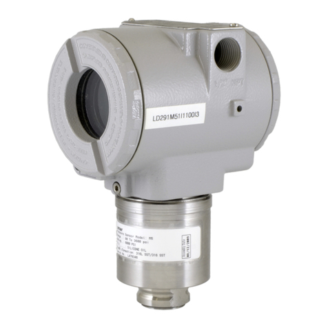
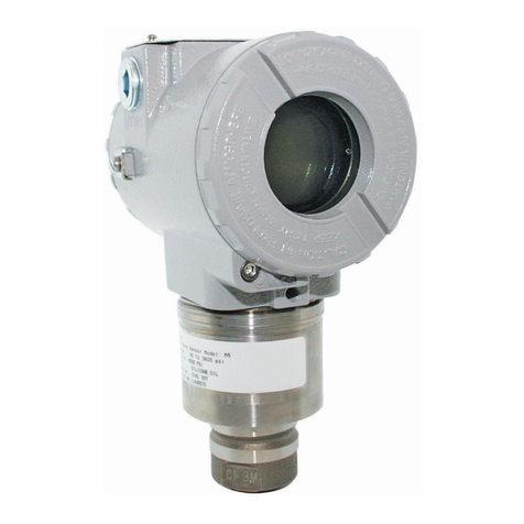
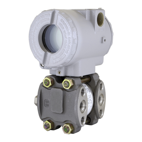
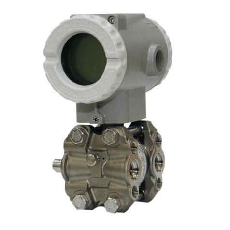
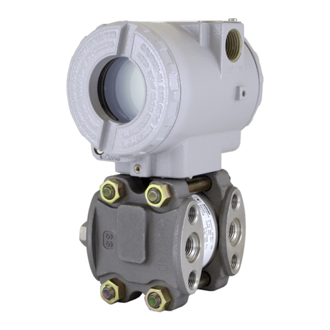
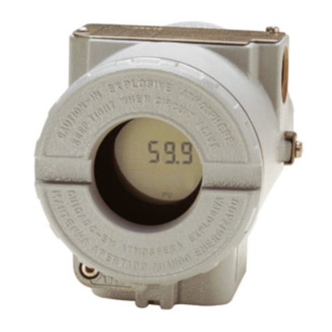
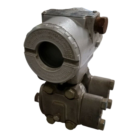
LD301 is a smart pressure transmitter for differential, absolute, gauge, level and flow
measurements. It is based on a field-proven capacitive sensor that provides reliable operation and
high performance. The digital technology used in LD301 enables the choice of several types of
transfer functions, an easy interface between the field and the control room and several interesting
features that considerably reduce installation, operation and maintenance costs.
Besides all the functions offered by other smart transmitters, LD301offers the following functions:
3
)( P- used for trapezoidal weirs in open channel flow measurement.
5
)( P- used for V-notch weirs in open channel flow measurement.
TABLE - the pressure signal is linearly customized according to a 16-point table, enabling, e.g.,
level-to-volume conversion of a horizontal cylindrical tank.
CONTROLLER - the Process Variable is compared to a set point. The deviation acts on the
output signal according to an optional PID algorithm.
PID OUTPUT CHARACTERIZATION - the PID output signal (MV) follows a curve that is
determined by 16 points, which can be freely configured
BIDIRECTIONAL FLOW FUNCTION - used to measure the flow in the piping in both directions.
LOCAL ADJUSTMENT - not Only for Lower and Upper value, but input/output function,
operation mode, indication, set point, PID parameters (optional) as well.
PASSWORD - three levels for different functions.
OPERATION COUNTER - shows the number of changes in each function.
TOTALIZATION - flow totalization in volume or mass.
USER-UNIT - indication in engineering unit of the property actually measured, e.g., level,
flow or volume.
WRITE-PROTECT - via hardware
Get the best results of the LD301 by carefully reading these instructions.
Smar pressure transmitters are protected by U.S. patents 6,433,791 and 6,621,443.

LD301 – Operation and Maintenance Instruction Manual
IV
NOTE
This manual is compatible with version 6.XX, where 6 notes software version and XX software
release. The indication 6.XX means that this manual is compatible with any release of version 6
software
WARNING
To ensure that our products are safe and without risk to health, the manual must be read carefully
before proceeding and warning labels on packages must be observed. Installation, operation,
maintenance and servicing must only be carried out by suitably trained personnel and in
accordance with the Operation and Maintenance Instruction Manual.
Waiver of responsibility
The contents of this manual abides by the hardware and software used on the current equipmen
t
version. Eventually there may occur divergencies between this manual and the equipment. The
information from this document are periodically reviewed and the necessary or identified corrections
will be included in the following editions. Suggestions for their improvement are welcome.
Warning
For more objectivity and clarity, this manual does not contain all the detailed information on the
product and, in addition, it does not cover every possible mounting, operation or maintenance
cases.
Before installing and utilizing the equipment, check if the model of the acquired equipment complies
with the technical requirements for the application. This checking is the user’s responsibility.
If the user needs more information, or on the event of specific problems not specified or treated in
this manual, the information should be sought from Smar. Furthermore, the user recognizes that the
contents of this manual by no means modify past or present agreements, confirmation or judicial
relationship, in whole or in part.
All of Smar’s obligation result from the purchasing agreement signed between the parties, which
includes the complete and sole valid warranty term. Contractual clauses related to the warranty are
not limited nor extended by virtue of the technical information contained in this manual.
Only qualified personnel are allowed to participate in the activities of mounting, electrical connection,
startup and maintenance of the equipment. Qualified personnel are understood to be the persons
familiar with the mounting, electrical connection, startup and operation of the equipment or othe
r
similar apparatus that are technically fit for their work. Smar provides specific training to instruct and
qualify such professionals. However, each country must comply with the local safety procedures,
legal provisions and regulations for the mounting and operation of electrical installations, as well as
with the laws and regulations on classified areas, such as intrinsic safety, explosion proof, increased
safety and instrumented safety systems, among others.
The user is responsible for the incorrect or inadequate handling of equipments run with pneumati
c
or hydraulic pressure or, still, subject to corrosive, aggressive or combustible products, since thei
r
utilization may cause severe bodily harm and/or material damages.
The field equipment referred to in this manual, when acquired for classified or hazardous areas, has
its certification void when having its parts replaced or interchanged without functional and approval
tests by Smar or any of Smar authorized dealers, which are the competent companies for certifying
that the equipment in its entirety meets the applicable standards and regulations. The same is true
when converting the equipment of a communication protocol to another. In this case, it is necessar
y
sending the equipment to Smar or any of its authorized dealer. Moreover, the certificates are
different and the user is responsible for their correct use.
Always respect the instructions provided in the Manual. Smar is not responsible for any losses
and/or damages resulting from the inadequate use of its equipments. It is the user’s responsibility to
know and apply the safety practices in his country.

Table of Contents
V
TABLE OF CONTENTS
SECTION 1 - INSTALLATION.....................................................................................................................1.1
GENERAL..................................................................................................................................................................1.1
MOUNTING...............................................................................................................................................................1.1
ELECTRONIC HOUSING..........................................................................................................................................1.9
WIRING ...................................................................................................................................................................1.10
LOOP CONNECTIONS...........................................................................................................................................1.11
INSTALLATION IN HAZARDOUS AREAS..............................................................................................................1.13
EXPLOSION/FLAME PROOF.................................................................................................................................1.13
INTRINSICALLY SAFE............................................................................................................................................1.13
SECTION 2 - OPERATION..........................................................................................................................2.1
FUNCTIONAL DESCRIPTION - SENSOR................................................................................................................2.1
FUNCTIONAL DESCRIPTION - HARDWARE..........................................................................................................2.2
FUNCTIONAL DESCRIPTION - SOFTWARE..........................................................................................................2.3
THE DISPLAY ...........................................................................................................................................................2.6
SECTION 3 - CONFIGURATION.................................................................................................................3.1
CONFIGURATION FEATURES................................................................................................................................3.5
MANUFACTURING DATA AND IDENTIFICATION..................................................................................................3.5
PRIMARY VARIABLE TRIM - PRESSURE...............................................................................................................3.6
PRIMARY VARIABLE CURRENT TRIM...................................................................................................................3.7
TRANSMITTER ADJUSTMENT TO THE WORKING RANGE.................................................................................3.7
ENGINEERING UNIT SELECTION...........................................................................................................................3.8
TRANSFER FUNCTION FOR FLOW MEASUREMENT ..........................................................................................3.9
TABLE POINTS.......................................................................................................................................................3.11
TOTALIZATION CONFIGURATION........................................................................................................................3.11
PID CONTROLLER CONFIGURATION..................................................................................................................3.12
EQUIPMENT CONFIGURATION............................................................................................................................3.13
EQUIPMENT MAINTENANCE................................................................................................................................3.15
SECTION 4 - PROGRAMMING USING LOCAL ADJUSTMENT................................................................4.1
THE MAGNETIC TOOL.............................................................................................................................................4.1
SIMPLE LOCAL ADJUST..........................................................................................................................................4.2
ZERO AND SPAN RERANGING ..............................................................................................................................4.3
COMPLETE LOCAL ADJUSTMENT.........................................................................................................................4.3
LOCAL PROGRAMMING TREE...............................................................................................................................4.3
OPERATION [OPER] ................................................................................................................................................4.4
TUNING [TUNE]........................................................................................................................................................4.6
CONFIGURATION [CONF].......................................................................................................................................4.8
RANGE (RANGE)......................................................................................................................................................4.9
FUNCTION (FUNCT)...............................................................................................................................................4.12
OPERATION MODE (MODE) .................................................................................................................................4.12
TOTALIZATION [TOTAL]........................................................................................................................................4.13
TOTALIZATION BRANCH (TOTAL)........................................................................................................................4.13
PRESSURE TRIM [TRIM] .......................................................................................................................................4.14
ESCAPE LOCAL ADJUSTMENT [ESC]..................................................................................................................4.15
SECTION 5 - MAINTENANCE.....................................................................................................................5.1
GENERAL..................................................................................................................................................................5.1
DIAGNOSTIC USING CONFIGURATION TOOL......................................................................................................5.1
ERROR MESSAGES.................................................................................................................................................5.1
DIAGNOSTIC VIA TRANSMITTER...........................................................................................................................5.2
DISASSEMBLY PROCEDURE.................................................................................................................................5.4
SENSOR..................................................................................................................................................................................5.4
ELECTRONIC CIRCUIT...........................................................................................................................................................5.4
REASSEMBLY PROCEDURE..................................................................................................................................5.6

LD301 – Operation and Maintenance Instruction Manual
VI
SENSOR..................................................................................................................................................................................5.6
ELECTRONIC CIRCUIT...........................................................................................................................................................5.7
INTERCHANGEABILITY...........................................................................................................................................5.8
RETURNING MATERIALS........................................................................................................................................5.8
SMAR INSULATOR KIT..........................................................................................................................................5.10
SMAR INSULATOR KIT MOUNTING .....................................................................................................................5.10
APPLICATION WITH HALAR..................................................................................................................................5.14
TECHNICAL SPECIFICATION ..............................................................................................................................................5.14
PERFORMANCE SPECIFICATION.......................................................................................................................................5.14
TPE – TOTAL PROBABLE ERROR (SOFTWARE)................................................................................................5.14
ORDERING CODE FOR THE SENSOR.................................................................................................................5.15
HART® SPECIAL UNITS........................................................................................................................................5.20
SECTION 6 - TECHNICAL CHARACTERISTICS .......................................................................................6.1
ORDERING CODE....................................................................................................................................................6.6
OPTIONAL ITEMS.....................................................................................................................................................6.7
OPTIONAL ITEMS.....................................................................................................................................................6.9
OPTIONAL ITEMS...................................................................................................................................................6.12
APPENDIX A - CERTIFICATIONS INFORMATION................................................................................... A.1
EUROPEAN DIRECTIVE INFORMATION................................................................................................................A.1
OTHERS APPROVALS.............................................................................................................................................A.1
SANITARY APPROVAL..........................................................................................................................................................A.1
MARINE APPROVAL..............................................................................................................................................................A.1
FMEDA REPORT:...................................................................................................................................................................A.1
HAZARDOUS LOCATIONS CERTIFICATIONS.......................................................................................................A.1
NORTH AMERICAN CERTIFICATIONS.................................................................................................................................A.1
EUROPEAN CERTIFICATIONS .............................................................................................................................................A.2
SOUTH AMERICA CERTIFICATION......................................................................................................................................A.3
ASIA CERTIFICATION............................................................................................................................................................A.3
IDENTIFICATION PLATE AND CONTROL DRAWING............................................................................................A.3
IDENTIFICATION PLATE .......................................................................................................................................................A.3
CONTROL DRAWING ............................................................................................................................................................A.7
APPENDIX B – SRF – SERVICE REQUEST FORM..................................................................................B.1
APPENDIX C – SMAR WARRANTY CERTIFICATE ................................................................................. C.1

Transmitter General View
VII
TRANSMITTER GENERAL VIEW
The LD301 uses a highly proven technique for pressure measuring by capacitance reading. The
block diagram of the LD301 HART® pressure transmitter is shown below.
Isolator
EEPROM with Sensor Data
Temperature Data
Resonant Oscillator
Digital
Reading
Zero/Span Local
Adjustment
- D/A Converter
- HART Modem
- LCD Controller
- Mathematical
Co-processor
- Range
- Special Functions
- PID
- Output Controller
- Communication
- HART
- Advanced Diagnostic
- Firmware Update
Process Unit
Protocol
SignalConditioner
Input/Output
PH PL
Digital
Sensor
Glass Metalized
Surface (4)
Ceramics
Filling Fluid (3)
Isolating
Diaphragm (2)
Sensor
Diaphragm (1)
HT3012
4 - 20mA
In the cell center is the sensor diaphragm (1). This diaphragm flexes in response to the different
pressures applied on the LOW and HIGH sides of the cell (PL and PH). These pressures are directly
applied on the isolator diaphragms (2), whose function is to isolate the sensor process and supply
high resistance against corrosion caused by process fluids. The pressure is transmitted directly to
the sensor diaphragm through the filling fluid (3) and causes its deflection. The sensor diaphragm is
a mobile electrode whose two metal surfaces (4) are stable electrodes. A deflection on the sensor
diaphragm is read by the capacitance variation between both stable and mobile electrodes.
The resonance oscillator reads the capacitance variations between the mobile and the stable boards
and generates a pressure output equivalent to the detected capacitance variation. This pressure
value is informed in compliance with the transmitter communication protocol. As the conversion
process does not involve an A/D converter, any errors or deviations are eliminated during the
process. Temperature compensation is done by a sensor, which combined with a precision sensor,
results in high accuracy and range.
The process variable, as well as the diagnostic monitoring and information, are supplied by the
digital communication protocol. The LD301 is available in the HART communication protocol.
Read carefully these instructions for better use of the LD301.

LD301 – Operation and Maintenance Instruction Manual
VIII
I
nsta
ll
at
i
on
Fl
owc
h
art
Was the transmitter
configured on the bench
to match the application?
Configure the transmitter
(Section 1 and 3)
Configure the measuring range
to 0% (4mA) and 100%
(20mA) (Section 3)
Configure the Fail-Safe
value (Section 3)
Configure the Damping (Section 3)
Configure the LCD reading
(Section 3)
Apply the pressure
Is the reading correct?
See manual
(Section 5) - Maintenance
Start
No
Yes
OK
Apply the Zero Trim
Is the impulse line wett leg?
Install the transmitter on the field
following the instructions below.
Install the transmitter preferably
on weather- protected areas.
Install the transmitter (mechanically
and electrically) according to the
application after checking the best
position for the LCD (Section 5)
Check the area classification
and its practices
Power the transmitter properly.
Did you correct the
transmitter reading?
Is the transmitter
reading correct?
Yes
No
No
Yes
Yes
No
Yes
No

Section 1
1.1
INSTALLATION
General NOTE
The installationcarried out in hazardousareas should followthe recommendations ofthe IEC 60079-14
standard.
The overall accuracyof a flow, level, or pressure measurement depends on severalvariables.Although
the transmitter has an outstanding performance, proper installation is essential to maximize its
efficiency.
Among all factors, which may affect transmitteraccuracy,environmental conditions arethe most difficult
to control. There are, however, ways of reducing the effects of temperature, humidity and vibration.
The LD301 has a built-in temperature sensor to compensate for temperature variations. At the factory,
each transmitter is submitted to a temperature cycle, and the characteristics under different
temperatures are recorded in the transmitter memory. At the field, this feature minimizes the
temperature variation effect.
Mounting
Putting the transmitter in areas protected from extreme environmental changes can minimize
temperature fluctuation effects.
In warm environments, thetransmitter shouldbe installedto avoid, as muchaspossible, direct exposure
to the sun. Installationclose to linesand vesselssubjected to high temperatures should alsobe avoided.
Use longer sections of impulse piping between tap and transmitter whenever the process fluidis at high
temperatures. Use of sunshades or heat shields to protect the transmitter from external heat sources
should be considered, if necessary.
Proper winterization (freeze protection) should be employed to prevent freezing within the measuring
chamber, since this will result in an inoperative transmitter and could even damage the cell.
Although the transmitter is virtually insensitive to vibration, installation close to pumps, turbines orother
vibrating equipment should be avoided.
The transmitter has been designed to be both rugged and lightweight at the same time. This makes its
mounting easier. The mounting positions are shown in Figure 1.1.
Existing standards for the manifolds have also been considered, and standard designs fits perfectly to
the transmitter flanges.
Should the process fluid contain solids in suspension, install valves or rod-out fittings regularly to clean
out the pipes. The pipes should be internally cleaned by using steam or compressed air, or bydraining
the line with the process fluid, before such lines are connected to the transmitter (blow-down).
NOTE
When installing or storing the level transmitter, the diaphragm must be protected toavoidscratching-
denting or perforation of its surface. The process flange of the level transmitters can be rotated 45º.
To do this just loosen the two screws (Figure 1.1) and rotate the flange. Do not take the screws out.
There is a label (Figure 1.1) on the transmitter with these instructions.

LD301 – Operation and Maintenance Instruction Manual
1.2
Figure 1.1 (a) – Dimensional Drawing and Mounting Position - Differential, Flow, Gage, Absolute and High Static Pressure
Transmitters with Mounting Bracket

Installation
1.3
Figure 1.1 (b) – Dimensional Drawing and Mounting Position - Flanged Pressure Transmitter with Integral Flange

LD301 – Operation and Maintenance Instruction Manual
1.4
Figure 1.1 (c) – Dimensional Drawing and Mounting Position - Flanged Pressure Transmitter with Slip-on Flange

Installation
1.5
Figure 1.1 (d) – Dimensional Drawing and Mounting Position - Flanged Pressure Transmitter with Housing

LD301 – Operation and Maintenance Instruction Manual
1.6
Figure 1.1 (e) – Dimensional Drawing and Mounting Position - Sanitary Transmitter without Extension

Installation
1.7
Figure 1.1 (f) – Dimensional Drawing and Mounting Position - Sanitary Transmitter with Extension

LD301 – Operation and Maintenance Instruction Manual
1.8
Figure 1.2 – Drawing of LD301 Mounted on the Panel or Wall
Observe operating safety rules during wiring, draining or blow-down.
WARNING
Normal safety precautions must be taken to avoid the possibility of an accident occurring when
operating in conditions of high pressure and/or temperature.
Electrical shock can result in death or serious injury.
Avoid contact with the leads and terminals.
Process leaks could result in death or serious injury.
Do not attempt to loosen or remove flange bolts while the transmitter is in service.
Replacement equipment or spare parts not approved by Smar could reduce the pressure
retaining capabilities of the transmitter and may render the instrument dangerous.
Use only bolts supplied or sold by Smar as spare parts.
Some examples of installation, illustrating the transmitter position in relation to the taps, are shown in
Figure 1.3. The pressure taps location and the relative positions ofthe transmitterareindicatedinTable
1.1.
Process Fluid Location of Location of LD301 in Relation to the Taps
Gas Top or Side Above the Taps
Liquid Side Below the Taps or at the Piping Centerline
Steam Side Below the Taps using Sealing (Condensate) Pots
Table 1.1 - Location of Pressure Taps
NOTE
For liquids, condensates, wet vapors and gases the impulse lines must be bent on the ratio 1:10 to
prevent bubbles from accumulating;
The transmitter and its impulse lines must be tightly fixed;
If necessary, install the condensate and mud pots;
Use manifold valves to facilitate maintenance and adjustments.
WALL OR PANEL MOUNTING
(See Section 5 – spare parts list
for mounting brackets available)

Installation
1.9
Figure 1.3 – Position of the Transmitter and Taps
NOTE
The transmitters are calibrated in the vertical positionand adifferent mounting position displacesthe
zero point. Consequently, the indicator will indicate a different value from the applied pressure. In
these conditions, it is recommended to do the zero pressure trim. The zero trim compensates the
final assembly position and its performance, when the transmitter is in its final position. When the
zero trim is executed, make sure the equalization valve is open and the wet leg levels are correct.
For the absolute pressure transmitter, the assembly effects correction should be done using the
Lower trim, due to the fact that the absolute zero is the reference for these transmitters, so there is
no need for a zero value for the Lower trim.
Electronic Housing
Humidity is fatal to electronic circuits. In areas subjected to high relative humidity, the O-rings for the
electronic housing covers must be correctly placedand thecovers must becompletely closedby tighten
them by hand until you feel the O-rings being compressed. Do not use tools to close the covers.
Removal of the electronics cover in the field should be reduced to the minimum necessary, since each
time it is removed; the circuits are exposed to the humidity.
The electronic circuit is protected by a humidity proof coating, but frequent exposures to humidity may
affect the protection provided. It is also important to keep the covers tightened in place. Every time they
are removed, the threads are exposed to corrosion, since painting cannot protect these parts. Sealing
methods should be employed on conduit entering the transmitter. The unused outlet connection should
be properly plugged.
WARNING
The unused cable entries should beplugged and sealed accordinglyto avoid humidity entering, which
can cause the loss of the product’s warranty.
DIAPHRAGM SENSOR
SENSOR IN THE VERTICAL POSITION SENSOR IN THE HORIZONTAL POSITION
HEAD OF THE FLUID
DIAPHRAGM SENSOR

LD301 – Operation and Maintenance Instruction Manual
1.10
The electronic housing can be rotated to adjust the digital display on a better position. Torotateit, loose
the Housing Rotation Set Screw, see Figure 1.4 (a). To prevent humidity entering, the electric housing
and the sensor joint must have a minimum of 6 fully engaged threads. The provided joint allows 1 extra
turn to adjust the position of the displaywindowby rotating the housing clockwise. If the thread reaches
the end before the desired position, then rotate the housing counterclockwise, but not more than one
thread turn. Transmitters have a stopper that restricts housing rotation to one turn. See Section 5,
Figure 5.2.
COVER
LOCKING
SCREW
(a) (b)
Figure 1.4 - Cover Locking and Housing Rotating Set Screw (a) Electronic Board Side
(b) Terminal Connection Side
Wiring
To access the wiring block, loosen the cover locking screw to release the cover. See Figure 1.4 (b).
Test and Communication terminals allow, respectively, to measure the current in the 4 - 20 mA loop,
without opening the circuit, and also to communicate with the transmitter. The “Test Terminals” must be
used to measure the current. The “COMM” terminal must be used for HART communication. The
terminal block has screws where fork or ring-type terminals can be fastened. See Figure 1.5.
POWER
SUPPLY
TERMINALS
AND HART
BUS
COMUNICATIONS
TERMINALS
LOCK
TEST
COMM
+
TEST
TERMINALS
®
OPTIONAL GROUND
TERMINAL
INTERNAL GROUND
TERMINAL
GROUND TERMINA
L
Figure 1.5 – Terminal Block
The LD301 is protected against reverse polarity.
For convenience there are three ground terminals: one inside the cover and two external, located close
to the conduit inlets.
Use of twisted pair (22 AWG or greater than) cables is recommended. For sites with high
electromagnetic levels (EMI above 10 V/m) shield conductors are recommended.
Avoid routing signal wiring near to power cables or switching equipment.
The Figure 1.6 shows the correct conduit installation, to avoid penetration of water or other substance,
which may cause equipment malfunction.

Installation
1.11
CORRECT
WIRES
INCORRECT
Figure 1.6 - Conduit Installation
Loop Connections
Figures 1.7 and 1.8 show LD301’s wiring diagrams to work as transmitter and controller, respectively.
Figure 1.9 shows the LD301’s wiring diagrams to work in the multi-drop network. Note that a maximum
of 15 transmitters can be connected on the same line and that they should be connected in parallel.
Take care to the power supply as well, when many transmitters are connected on the same line. The
current through the 250 Ohm resistor will be high causinga highvoltage drop. Therefore make sure that
the power supply voltage is sufficient.
The Hand-Held Terminal can be connected to the communication terminals of the transmitter or at any
point of the signal line by using the alligator clips. It is also recommended to ground the shield of
shielded cables at only one end. The ungrounded end must be carefully isolated. On multi-drop
connections, the circuit loop integritymust beassured, withspecial care toprevent short-circuit between
the circuit loop and the housing.
NOTE
For HART transmitters to operate in multi-drop mode each transmitter must be configured with a
different identity Device ID. In addition, if the transmitter identification mode on the loop is done
through the Command 0 address, the HART address must also be different. If it is done through the
(Command 11) Tag the Tags must be similar.
Figure 1.7 - Wiring Diagram for the LD301 Working as a Transmitter

LD301 – Operation and Maintenance Instruction Manual
1.12
Figure 1.8 - Wiring Diagram for the LD301 Working as a Controller
Figure 1.9 - Wiring Diagram for the LD301 in Multidrop Configuration
NOTE
Make sure that the transmitter is operating within the operating area as shown on the load curve
(Figure 1.10). Communication requires a minimum load of 250 Ohm and voltage equal to 17 Vdc.
Figure 1.10 – Load Limitation
Other manuals for ld301
1
Table of contents
Other SMAR Transmitter manuals
Popular Transmitter manuals by other brands

Kenwood
Kenwood T-599A user manual

Cables to Go
Cables to Go TV AVS 815 manual
Marti Electronics
Marti Electronics SRPT-40A user manual

Zhongshan K-mate General Electronics
Zhongshan K-mate General Electronics AT1900 user manual

Vaisala
Vaisala HUMICAP HMT140 quick guide

DMP Electronics
DMP Electronics 1139 installation guide
Luxi Electronics
Luxi Electronics TPR-150CR Presenter quick start guide
Canon
Canon WFT-E2 instruction manual
TESTO
TESTO 6682 Safety instructions

Promate
Promate FM12 user guide
Zhongshan K-mate General Electronics
Zhongshan K-mate General Electronics AT009 user manual
Kistler
Kistler 9238B Series instruction manual

