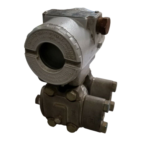
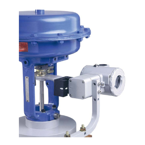
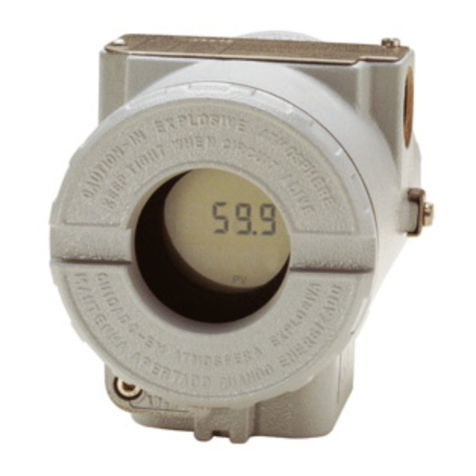
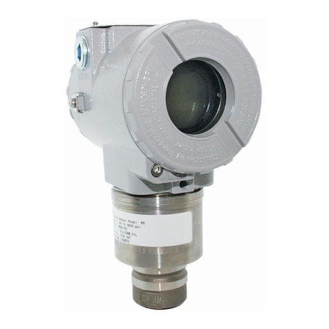
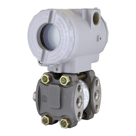
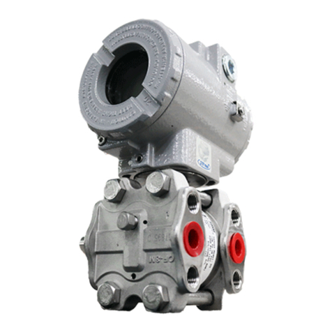
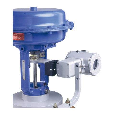
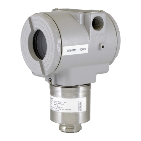
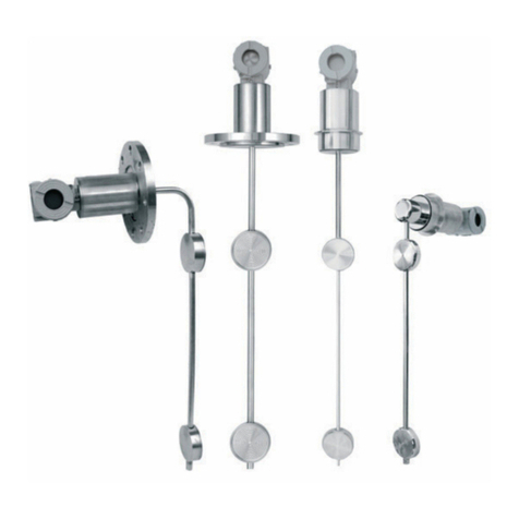
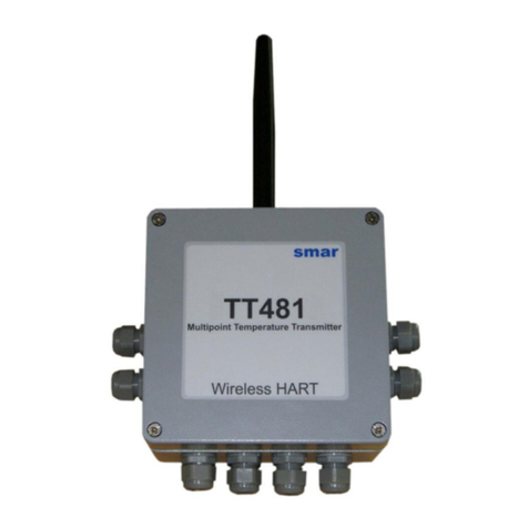
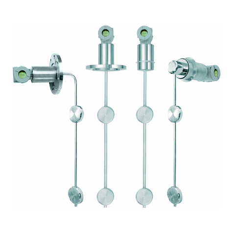
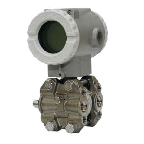
SMAR Foundation 302 Series User manual


web: www.smar.com
smar
Specifications and information are subject to change without notice.
For the latest updates, please visit the SMAR website above.
BRAZIL
Smar Equipamentos Ind. Ltda.
Rua Dr. Antonio Furlan Jr., 1028
Sertãozinho SP 14170-480
Tel.: +55 16 3946-3510
Fax: +55 16 3946-3554
ARGENTINA
Smar Argentina
Soldado de La Independencia, 1259
(1429) Capital Federal – Argentina
Telefax: 00 (5411) 4776 -1300 / 3131
CHINA
Smar China Corp.
3 Baishiqiao Road, Suite 30233
Beijing 100873, P.R.C.
Tel.: +86 10 6849-8643
Fax: +86-10-6894-0898
FRANCE
Smar France S. A. R. L.
42, rue du Pavé des Gardes
F-92370 Chaville
Tel.: +33 1 41 15-0220
Fax: +33 1 41 15-0219
GERMANY
Smar GmbH
Rheingaustrasse 9
55545 Bad Kreuznach
Germany
Tel: + 49 671-794680
Fax: + 49 671-7946829
MEXICO
Smar México
Cerro de las Campanas #3 desp 119
Col. San Andrés Atenco
Tlalnepantla Edo. Del Méx - C.P. 54040
Tel.: +53 78 46 00 al 02
Fax: +53 78 46 03
SINGAPORE
Smar Singapore Pte. Ltd.
315 Outram Road
#06-07, Tan Boon Liat Building
Singapore 169074
Tel.: +65 6324-0182
Fax: +65 6324-0183
USA
Smar International Corporation
6001 Stonington Street, Suite 100
Houston, TX 77040
Tel.: +1 713 849-2021
Fax: +1 713 849-2022
Smar Laboratories Corporation
10960 Millridge North, Suite 107
Houston, TX 77070
Tel.: +1 281 807-1501
Fax: +1 281 807-1506
Smar Research Corporation
4250 Veterans Memorial Hwy.
Suite 156
Holbrook , NY 11741
Tel: +1-631-737-3111
Fax: +1-631-737-3892

Index
III
Table of Contents
INDEX OF FIGURES................................................................................................... IV
INDEX OF TABLES .................................................................................................... IV
INTRODUCTION.......................................................................................................... V
INSTALLATION ........................................................................................................ 1.1
NETWORK WIRING .............................................................................................................................1.1
PHYSICAL SIGNALING........................................................................................................................1.2
TOPOLOGIES ......................................................................................................................................1.2
BUS TOPOLOGY .................................................................................................................................1.2
TREE TOPOLOGY ...............................................................................................................................1.2
DAISY CHAIN TOPOLOGY..................................................................................................................1.5
POINT-TO-POINT TOPOLOGY............................................................................................................1.6
FIELDBUS NETWORK COMPONENTS ..............................................................................................1.6
POWER SUPPLY .................................................................................................................................1.6
DEVICE QUANTITY .............................................................................................................................1.7
TERMINAL BLOCKS ............................................................................................................................1.7
TERMINATOR ......................................................................................................................................1.7
TERMINATOR PLACEMENT ...............................................................................................................1.8
PSI302 POWER SUPPLY IMPEDANCE ..............................................................................................1.8
REDUNDANT POWER.........................................................................................................................1.9
BT302 TERMINATOR...........................................................................................................................1.9
PS302 POWER SUPPLY .....................................................................................................................1.9
CABLING ..............................................................................................................................................1.9
CABLE OPTIONS...............................................................................................................................1.10
TOTAL CABLE LENGHT ....................................................................................................................1.10
SPUR LENGHT ..................................................................................................................................1.13
RECOMMENDED MAXIMUM SPUR LENGHT .................................................................................1.13
INTERFACE AND BRIDGE ................................................................................................................1.14
BRIDGE CONNECTION .....................................................................................................................1.14
INTRINSIC SAFETY CONNECTION ..................................................................................................1.15
INTRINSIC SAFETY...........................................................................................................................1.15
ATTACHING DEVICES TO THE FIELDBUS......................................................................................1.19
WIRING DOS AND DON’TS...............................................................................................................1.29
INTRINSIC SAFETY GALVANIC ISOLATOR.....................................................................................1.20
COMPUTER INSTALLATION.............................................................................................................1.21
INTERFACE CONNECTION ..............................................................................................................1.21
INTERFACE ADDRESING .................................................................................................................1.22
INTERFACE CONFIGURATION.........................................................................................................1.22
BASIC TROUBLESHOOTING ............................................................................................................1.23
OPERATION ............................................................................................................. 2.1
THE LCD DISPLAY .............................................................................................................................2.1
NORMAL DISPLAY OPERATION ........................................................................................................2.2
CONFIGURATION .................................................................................................... 3.1
FUNCTION BLOCKS............................................................................................................................3.1
DISPLAY TRANSDUCER BLOCK........................................................................................................3.1
LOCAL PROGRAMMING TREE...........................................................................................................3.3
DISPLAY CONFIGURATION USING SYSCON ...................................................................................3.3
PROGRAMMING USING LOCAL ADJUSTMENT ...............................................................................3.5
LOCAL ADJUSTMENT METHODOLOGY............................................................................................3.5
TRANSDUCER BLOCK........................................................................................................................3.7
HOW CONFIGURE A TRANDUCER BLOCK.......................................................................................3.7
CHANNEL.............................................................................................................................................3.8
CALIBRATION......................................................................................................................................3.8

FoundationTM Fieldbus Series 302 – Installation, Operation and Maintenance Manual
IV
MAINTENANCE PROCEDURES .............................................................................. 4.1
GENERAL.............................................................................................................................................4.1
RETURNING SMAR PRODUCTS AND/OR MATERIALS ....................................................................4.1
Index of Figures
FIGURE 1.1 – HOUSING ROTATION.........................................................................................................1.1
FIGURE 1.2 – WIRING BLOCK ..................................................................................................................1.1
FIGURE 1.3 – WIRE MEDIA.......................................................................................................................1.2
FIGURE 1.4 – FIELDBUS NETWORK........................................................................................................1.3
FIGURE 1.5 – BUS TOPOLOGY ................................................................................................................1.4
FIGURE 1.6 – TREE TOPOLOGY ..............................................................................................................1.4
FIGURE 1.7 – DAISY – CHAIN TOPOLOGY..............................................................................................1.5
FIGURE 1.8 – DAISY – CHAIN WIRING ....................................................................................................1.5
FIGURE 1.9 – POINT-TO-POINT TOPOLOGY ..........................................................................................1.6
FIGURE 1.10 – TERMINAL BLOCKS .........................................................................................................1.7
FIGURE 1.11 – PSI302 CONNECTION......................................................................................................1.8
FIGURE 1.12 – REDUNDANT POWER......................................................................................................1.9
FIGURE 1.13 – TOTAL CABLE LENGHT.................................................................................................1.10
FIGURE 1.14 – CABLE ENTITY PARAMETERS......................................................................................1.11
FIGURE 1.15 – GROUNDING THE SHIELD ............................................................................................1.12
FIGURE 1.16 – SPUR LENGHT AND TERMINATOR PLACEMENT .......................................................1.13
FIGURE 1.17 – BRIDGE CONNECTION ..................................................................................................1.14
FIGURE 1.18 – I. S. CONNECTION .........................................................................................................1.15
FIGURE 1.19 – REPEATER CONNECTION ............................................................................................1.18
FIGURE 1.20 – IF302 CONNECTION.......................................................................................................1.18
FIGURE 1.21 – FI302 CONNECTION.......................................................................................................1.18
FIGURE 1.22 – CONNECTION.................................................................................................................1.20
FIGURE 1.23 – IF302 IN I. S. INSTALLATION .........................................................................................1.20
FIGURE 1.24 – FI302 IN I. S. INSTALLATION .........................................................................................1.21
FIGURE 1.25 – INTERFACE CONNECTION ...........................................................................................1.21
FIGURE 1.26 – INTERFACE ADDRESSING ...........................................................................................1.22
FIGURE 2.1 – TYPICAL NORMAL DISPLAY SHOWING PV, IN THIS CASE 50.0%.................................2.2
FIGURE 2.2 – LCD DISPLAY .....................................................................................................................2.2
FIGURE 3.1 – FUNCTION AND TRANDUCERS BLOCKS ........................................................................3.2
FIGURE 3.2 – TRANSDUCER DISPLAY – CONFIGURATION..................................................................3.2
FIGURE 3.3 – THE SETINGS OF TRANDUCER DISPLAY PARAMETERS..............................................3.3
FIGURE 3.4 – THE SETINGS OF TRANDUCER DISPLAY PARAMETERS II...........................................3.4
FIGURE 3.5 – THE SETINGS OF TRANDUCER DISPLAY PARAMETERS II...........................................3.4
FIGURE 3.6 – THE SETINGS OF TRANDUCER DISPLAY PARAMETERS II...........................................3.5
FIGURE 3.7 – LOCAL ADJUSTMENT SWITCHES ....................................................................................3.5
FIGURE 3.8 – BROWSING GENERIC PARAMETER ................................................................................3.6
FIGURE 3.9 – ACTING A GENERIC VALUE..............................................................................................3.6
Index of Tables
TABLE 1.1 – CABLE OPTIONS ................................................................................................................1.10
TABLE 1.2 – TOTAL CABLE LENGHT EXAMPLE ...................................................................................1.11
TABLE 1.3 – DEVICES PER SPUR VS. SPUR LENGHT.........................................................................1.13
TABLE 1.4 – TEMPERATURE CLASSIFICATIONS .................................................................................1.16
TABLE 2.1 – DISPLAY MESSAGES...........................................................................................................2.3
TABLE 3.1 – PARAMETER FUNCTION AND CLASS DEFAULT OF DEVICE ..........................................3.3
TABLE 3.2 – TRANSDUCER DISPLAY PARAMETERS ............................................................................3.4
TABLE 4.1 – DIAGNOSTIC OF THE FIELD DEVICES...............................................................................4.1

Introduction
V
Introduction
This manual introduces the series 302 of Fieldbus Foundation devices.
They are: LD302 – FOUNDATIONFieldbus Pressure Transmitter, TT302 – FOUNDATION
Fieldbus Temperature Transmitter, IF302 – FOUNDATIONFieldbus Triple Channel Current
to Fieldbus Converter, FI302 – FOUNDATIONFieldbus Triple Channel Fieldbus to Current
Converter, FP302 - FOUNDATIONFieldbus to Pressure Converter and FY302 -
FOUNDATIONFieldbus Positioner.
They are based on a field-proven technology that provides reliable operation and high
performance. The digital technology used in the Series 302 enables the choice of several
types of function blocks. An easy interface between the field and the control room and several
interesting features that considerably reduce the installation, operation and maintenance costs
and will develop new ways to improve plant performance, plant safety and plant availability.
Fieldbus is not only a replacement for 4-20 mA or intelligent device protocols, it contains much
more. Fieldbus is a complete network system enabling migration and distribution of the control
functions to field devices, and vastly expands the amount of process and non-process
information flowing both from and to field devices.
Some of the advantages of bi-directional digital communications are known from existing
smart field devices protocols: Higher accuracy, multi-variable access, remote configuration
and diagnostics, and multi-dropping of several devices on a single pair of wires. Those
protocols were not intended to transfer control data, but maintain information. Therefore, they
were slow, being not efficient enough to be used to digital control by communication and not
giving opportunity to come to control strategies totally reside in the field.
Fieldbus overcame these limitations. Closed loop control with performance like a 4-20 mA
system requires higher speed. Since higher speed requires higher power consumption, this
clashes with the need for intrinsic safety. Therefore a moderately high communication speed
was selected, and the system was designed to have minimum communication over-head.
Using scheduling, the system controls the variables poling, algorithm execution and the traffic
to optimize the network usage, thus achieving high and secure closed loop performance.
Using FoundationFieldbus technology, with its capability to interconnect several devices,
very large control schemes can be constructed. In order to be user friendly, the function blocks
concept was introduced1, it means, basic automation functions performed by an application.
Each function block processes input parameters according to a specified algorithm and an
internal set of contained parameters. They produce output parameters that are available for
use within the same device or by other one in the application process. Using them, the user
may easily build and overview complex control strategies. Another advantage can be seen as
extending flexibility, considering that the control strategy may be edited without having to re-
wire or change any hardware.
Each field device has a set of blocks likes Analog Input, PID, Control Selector, etc., eliminating
the need for a separate control devices. The communication requirement is considerably
reduced, and that means less dead-time and tighter control is achieved, not to mention the
reduction in cost. Other function blocks are also available2. They allow flexibility in control
strategy implementation and guarantee interoperability together of Device Description.
The need for implementation of fieldbus in small as well as large systems was considered
when developing the Series 302 of fieldbus devices. They have a common feature of being
able to act as a master on the network and be configured locally using a magnetic tool,
eliminating the need for a configurator or console in very basic applications.
Get the best results of the Foundation
Fieldbus Series 302 by carefully reading these
instructions.
1 Users of SMAR CD600 multi-loop digital controller should be familiar with this, since it was implemented several years ago.
2 For more details, Please look at Function Blocks Instruction Manual

FoundationTM Fieldbus Series 302 – Installation, Operation and Maintenance Manual
VI
WARNING
This Manual is compatible with version 3.XX, where 3 denote
software version and XX software release. The indication 3.XX
means that this manual is compatible with any release of Series
302 field devices with software version 3.

Section 1
1-1
Installation
Network Wiring
Access the wiring block by removing the Electrical Connection Cover. This cover can be
locked closed by the cover locking screw to release the cover, rotate the locking screw
clockwise. (See Figure 1.1 - Housing Rotation).
Figure 1.1 - Housing Rotation
Cable access to wiring connections is obtained by one of the two outlets. Conduit threads
should be sealed by means of code-approved sealing methods. The unused outlet connection
should be plugged accordingly.
The wiring block has screws on which fork or ring-type terminals can be fastened. (See Figure
1.2 - Wiring Block).
For convenience there are two ground terminals: one inside the cover and one external,
located close to the conduit entries.
Avoid routing signal wiring close to power cables or switching equipment.
Figure 1.2 - Wiring Block
GEREM101.CDR
GEREM102.CDR

FoundationTM Fieldbus Series 302 – Installation, Operation and Maintenance Manual
1-2
WARNING
HAZARDOUS AREAS
In hazardous zones with explosion proof requirements, the
covers must be tightened with at least 7 turns. In order to avoid
moisture or corrosive gases, hand tighten the covers until the O-
rings are compressed. Lock the covers closed with the locking
screw.
In hazardous zones with intrinsically safe or non-incendive
requirements, the circuit entity parameters and applicable
installation procedures must be observed.
Cable access to wiring connections is obtained by one of the two
conduit outlets. Conduit threads should be sealed by means of
code-approved sealing methods. The unused outlet connection
should be plugged accordingly.
Should other certifications be necessary, refer to the certification
or specific standard for installation limitations.
The Series 302 devices are protected against reverse polarity, and can withstand up to 35
VDC without damage.
Physical Signaling
The Foundation
Fieldbus Series 302 devices use the 31.25 kbit/s voltage mode wire
media option for the physical signaling. All devices on the same bus must use the same
signaling. All devices are connected in parallel along the same pair of wires.
Various types of fieldbus devices may be connected on the same bus. The Series 302 device
is powered via bus. The limit for such devices is 16 for one bus for non-intrinsically safe
requirements.
In hazardous areas, the number of devices may be limited to 4 devices per safety barrier by
intrinsically safe restrictions.
One fieldbus network may have many barriers.
Bus-Powered
(Field device takes power from the bus)
Non Bus-Powered
(Field devices gets power over separate wires)
Figure 1.3 - Wire Media
A Smar fieldbus System consists of several fieldbus networks. A fieldbus network may consist
of several segments. Several fieldbus devices may be connected to each segment
GEREM103.CDR

Installation
1-3
Figure 1.4 - Fieldbus Network
Topologies
Almost any topology is possible. It is mainly a matter of where the terminator is connected.
•Bus
•Tree (Chicken-foot)
•Daisy-chain
•Point-to-point
As far as fieldbus is concerned that are all alike, what matters is the placement of the
terminator.
Of course combinations of two or more topologies is possible.
NOTE
Ring topology is not possible. Because connecting the bus in a
ring damage the Termination scheme.
GEREM104.CDR

FoundationTM Fieldbus Series 302 – Installation, Operation and Maintenance Manual
1-4
Bus Topology
Devices are distributed along the trunk connected through spurs. A spur may be up to 120 m
long.
Figure 1.5 - Bus Topology
Tree topology
A main trunk runs from the control room into the field where it branches out to the individual
devices.
For tree topology it is important to ensure that the spur length does not exceeds the maximum
allowed.
Figure 1.6 - Tree Topology
GEREM105.CDR
GEREM106.CDR

Installation
1-5
Daisy Chain Topology
Cable is chained from device to device.
It is important to ensure that a device may be disconnected without other devices also being
disconnected. Therefore make sure to use same conduit for ”in” and “out” wires in order to
enable removal of device without interrupting bus.
Figure 1.7 - Daisy-Chain Topology
Figure 1.8 - Daisy-Chain Wiring
GEREM108.CDR
GEREM107.CDR

FoundationTM Fieldbus Series 302 – Installation, Operation and Maintenance Manual
1-6
Point-to-Point Topology
Only two devices connected to each other. This topology does not take advantage of the
multidrop capability of fieldbus. Typically used only on workbench with device and notebook
computer.
Figure 1.9 - Point-to-Point Topology
Fieldbus Network Components
•Cable (“Media”)
•Field devices
•Transmitters
•Valve positioners
•Converters
•Programmable controllers
•Interfaces
•Operator stations
•Hand-held terminals
•Terminator
•Power supply impedance and power supply
•Intrinsic safety barriers / Galvanic Isolators
•Bus analyzer
Power Supply
The power consumption varies from one device to another. There are no upper or lower limits.
The power consumption is indicated on device. The lower consumption a device has the
better, especially in intrinsic safety applications. It is important that the wire resistance is not
too high making the supply voltage at the device too low. Good connections and junctions
must be made to keep resistance low. It is possible to test the voltage (not signal) on the
installed network using a hand-held Digital voltmeter (DVM).
Power Supply Example
•PSI302 output voltage is 16 V (worst case)
•Cable resistance for 1.9 km is 84 ohm
•Device needs minimum 9 V
•Maximum voltage drop is 7 V
•Maximum total current draw is 83 mA
•Each device needs 15 mA
•Maximum 5 devices, or shorter cable
GEREM109.CDR

Installation
1-7
Device Quantity
Rules of thumb:
32 separately powered or 12 bus-powered plus an interface.
4 per safety barrier in hazardous area (one fieldbus network may have many barriers). More or
less devices may be possible depending on wire size and length, power consumption and
barrier rating.
Using repeaters more devices are theoretically possible (224), though there is a penalty on
control cycle time and display update.
Terminal Blocks
No special terminal blocks are required and no special couplers are required to join spurs to
trunk. Keep it inside a junction box.
Figure 1.10 - Terminal Blocks
Terminator
The terminator has two major functions:
•Signal current shunt: The communication signal is transmitted as a current but received as
a voltage, the terminator does the conversion.
•Prevent signal reflection: The communication signal bounces back when it reaches the end
of the wire, potentially distorting itself. The terminator prevents that. There are actually two
terminators in a fieldbus network, one in each end. However, one of them is typically built into
the power supply impedance or safety barrier.
Terminator - shunt
The low-speed wire media fieldbus signal is transmitted as an AC current with amplitude of 10-
20 mA.
Each of the two terminators has impedance of 100 ohm, and since they are connected in
parallel the network will have resulting impedance of 50 ohm.
The terminator will cause a voltage drop as the transmitted current passes through. A voltage
with amplitude of 250-500 mV will therefore be seen over the network. The receivers in all the
other fieldbus devices sense this voltage.
Terminator - end
When the fieldbus signal traveling down the wire reaches the end, it is faced with a change in
impedance from the characteristic impedance of the wire to the infinite impedance of open air.
This will cause a part of the signal power to be reflected back up through the wire. The
reflected signal interferes with the oncoming "real" signal. If the reflected signal is powerful
enough, it may distort the "real" signal such that the communication does not work. The
terminator has the same impedance as the cable such that when placed at the end the
fieldbus signal sees no change in impedance and hence there is no reflection. It is also clear
that the terminator must be at the end of the wire to really work.
GEREM110.CDR

FoundationTM Fieldbus Series 302 – Installation, Operation and Maintenance Manual
1-8
Terminator Placement
The terminator should be placed at each end of the trunk. The power supply impedance
PSI302 has one of the terminators built in. In bus topology the end of the trunk is easy to see.
In tree topology the end of the trunk is where the spurs branch out. There may never be more
than two terminators, and the terminators must not be forgotten. The bus may function with
only one terminator, but performance may be degraded.
PSI302 Power Supply Impedance
•Allows use of standard power supplies.
•18 +/-2 V, 300 mA output.
•Built-in terminator
•DIN-rail or panel mount
•Fail indication
A power supply impedance module shall be connected between the fieldbus and the power
supply. Prevents short circuit of communication signal by the power supply. The power supply
impedance also regulates the power supply voltage. If a normal power supply is connected
directly to the fieldbus the communication will be short-circuited, the power supply impedance
prevents this. The power supply impedance has built functionality for automatic and bumpless
switch over from a main to a backup in redundant configuration should the main unit not
provide power
Connect maximum 4 channels per PSI302 per PS302.
Figure 1.11 - PSI302 Connection
NOTE
AC Short Circuit Prevention
A DC power supply acts as a short on a AC circuit. Therefore the
power supply impedance is introduced. The impedance acts as a
3kΩimpedance between field
GEREM111.CDR

Installation
1-9
Redundant Power
Automatic bumpless switchover between redundant power supplies. Only one PSI302 should
have the terminator connected, or a separate power supply-end terminator is used.
Figure 1.12 - Redundant Power
BT302 Terminator
Intrinsically safe, equivalent unprotected capacitance.
PS302 Power Supply
•Wide input range:
90-264 VAC (47-440 Hz)
127-367 VDC
•24 VDC, 1.5 A output; up to four PSI302.
•Galvanically isolated
•Failure indication and output
Cabling
Several types of cable may be used, though shielded twisted pair is recommended. Depending
on the size and other factors of the cable the maximum length can vary varies. Four cable
types have been identified, though there are many more options. No special cable is required.
Normal instrument wires may be used. However, "fieldbus cable" is available from several
vendors to make selection easier.
GEREM112.CDR

FoundationTM Fieldbus Series 302 – Installation, Operation and Maintenance Manual
1-10
Cable Options
Type A is recommended for best possible performance.
Pair
Shield
Twist
Size
Max Length
Type
Single
Y
Y
0.75 mm2
1900 m
A
Multi
Y
Y
0.32 mm2
1200 m
B
Multi
N
Y
0.13 mm2
400 m
C
Multi
Y
N
1.25 mm2
200 m
D
Table 1.1 - Cable Options
For non-twisted cable the distance is very short even for thick and shielded wire.
NOTE
Detail characteristics for type “A”
Zo @ 31.25 kHz = 100 ohm +/- 20 %
Max attenuation @ 39 kHz = 3 dB/km
Max capacitive unbalance to shield = 2 nF/km
Max DC resistance per conductor = 22 ohm/km
Max propagation delay change 7.8-39 kHz = 1.7 us/km
Conductor cross-sectional area = 0.75 mm2
Total Cable Length
Maximum total cable length depends on the cable used. The total length includes the trunk
and all spurs.
Figure 1.13 - Total Cable Length
GEREM113.CDR

Installation
1-11
Segment
Length
Trunk
240 m
Spur 1
80 m
Spur 2
120 m
Spur 3
40 m
Total
480 m
Table 1.2 - Total Cable Length Example
Entity Parameter Example
It is good practice to make a table for each segment (barrier) listing the entity parameters for
each part for easy analysis
Cable Entity Parameters
Pay attention to capacitance and inductance of cables. Typically the L/R ratio of a cable is
used rather than just L since R cancels the effect of L. Typical cable values:
•L/R = 25 uH/ohm
•C = 200 nF/km
Figure 1.14 - Cable Entity Parameters
Normally the capacitance is the limiting factor for cable length in a fieldbus network. A 1.9-km
cable would contribute 380 nF, more than a barrier can handle.
GEREM114.CDR

FoundationTM Fieldbus Series 302 – Installation, Operation and Maintenance Manual
1-12
NOTE
Mixing Cable Types
To check if a combination of cable types is within the
specification the below equation may be used:
L1/L1max + L2/L2max + … < 1
Where:
L1 is length of cable type 1
L2 is length of cable type 2
L1max is the maximum length for cable type 1
L2max is the maximum length for cable type 2
Example:
L1 = 1000 m of cable type A
L2 = 100 m of cable type B
1000/1900 + 100/1200 = 0.61
Which is acceptable since 0.61 < 1
Cable Shield
Shield is preferred to achieve best performance. Shield should cover minimum 90% of the
cable length. If there is no shielding the cable should be within a metal conduit, which act as a
shield.
Grounding
Only the shield should be grounded never the fieldbus wires. The shield should be grounded in
only one point. The shield of the spurs shall be connected to the shield of the trunk. In high
EMI/RFI environments several additional RF grounds of the shield may be done using
capacitors, though this is rare. Do not use the shield as a conductor. The shield should be
grounded at the negative terminal of the power supply.
Figure 1.15 - Grounding the Shield
GEREM115.CDR

Installation
1-13
Spur Length
Remember that in tree like topologies the branches are actually spurs. Spur length is basically
independent of cable type as long as the maximum total length is not exceeded, but depends
on the number of devices connected to the spur. There should never be more than four
devices per spur. No special connectors are required to connect the spur to the trunk. Spurs
should be used to connect devices to the trunk so that one device may be removed without
disturbing the other.
Figure 1.16 - Spur Length and Terminator Placement
Recommended Maximum Spur Length
Total
1 per spur
2 per spur
3 per spur
4 per spur
25-32
1 m
1 m
1 m
1 m
19-24
30 m
1 m
1 m
1 m
15-18
60 m
30 m
1 m
1 m
13-14
90 m
60 m
30 m
1 m
1-12
120 m
90 m
60 m
30 m
Table 1.3 - Devices per spur vs. spur length
These lengths are rules of thumb. Longer is very often possible.
Spur Precautions
It is important to pay attention to spur length when star topology is used since the spurs in this
case is often quite long in comparison with bus topology. If the distance between the PSI302
and the PCI is more than 120 m (maximum spur length) then the internal terminator in the
PSI302 cannot be used, and a separate BT302 should instead be used.
Polarity
Some devices have polarity, others don't. It is important to ensure correct polarity for devices
with polarity. In a fieldbus system all devices are connected in parallel, i.e. all negative
terminals together, and all positive terminals together. Use of color-coded wires is
recommended to distinguish positive from negative.
GEREM116.CDR

FoundationTM Fieldbus Series 302 – Installation, Operation and Maintenance Manual
1-14
Interface and Bridge
An interface is used to connect a computer to the fieldbus. There are two types:
•Permanent installation
•Temporary connection
A bridge is used to pass data between networks.
Bridge Connection
Data may be passed between devices on different channels on the same PCI card, or even
between different PCI cards.
Figure 1.17 - Bridge Connection
GEREM117.CDR
This manual suits for next models
6
Table of contents
Other SMAR Transmitter manuals
Popular Transmitter manuals by other brands
M-system
M-system Mini-M M2RTS instruction manual

IMI SENSORS
IMI SENSORS 682B03 Installation and operating manual
Hanna Instruments
Hanna Instruments HI 8666 instruction manual

Suntex
Suntex PC-3310 Operation manuals
Tele Radio
Tele Radio T60TX-0 STL installation instructions

SenseAir
SenseAir aSENSE installation manual

Q5X
Q5X QT-5100 manual
Endress+Hauser
Endress+Hauser HART Flowmeter Proline 400 Brief operating instructions

Ramsey Electronics
Ramsey Electronics CUBE 2000 instruction manual

steute
steute RF 10 ST SW868 Mounting and wiring instructions
Sennheiser
Sennheiser SK 5012 instruction manual

GF Signet
GF Signet 8750-2 manual
