PC or MAC
Local Monitor
Plasma TV
Plasma TV
CAT6-STP
CAT6-STP
DVI-D DVI-D
5V
5V
5V
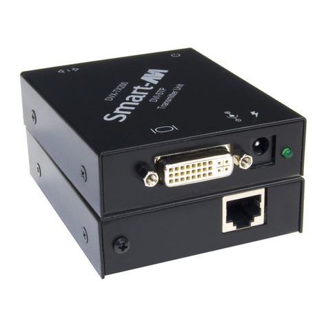
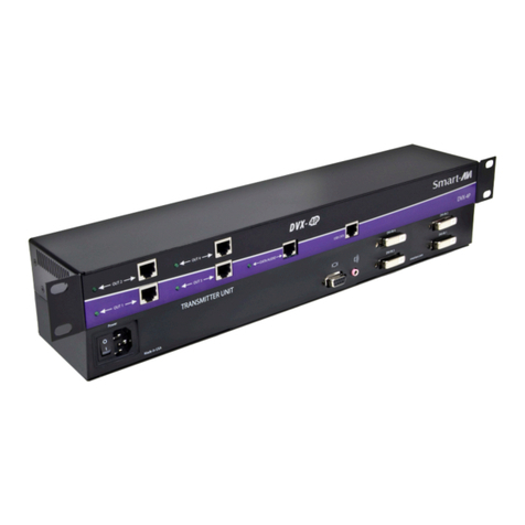
DVS200
Transmitter
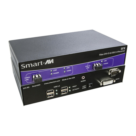
DVXRX200
Reciever
DVXRX200
Reciever
Technical Specifications
Input/Output Signal
#niPlangiS#niPlangiS
1-2ataDS.D.M.T61tceteDgulPtoH
2+2ataDS.D.M.T71-0ataDS.D.M.T
3dleihS4/2ataDS.D.M.T81+0ataDS.D.M.T
4-4ataDS.D.M.T91dleihS5/0ataDS.D.M.T
5+4ataDS.D.M.T02-5ataDS.D.M.T
6kcolCCDD12+5ataDS.D.M.T
7ataDCDD22dleihSkcolCS.D.M.T
8cnyS.treVgolanA32+kcolCS.D.M.T
9-1ataDS.D.M.T42-kcolCS.D.M.T
01+1ataDS.D.M.T
11dleihS3/1ataDS.D.M.T1CdeRgolanA
21-3ataDS.D.M.T2CneerGgolanA
31+3ataDS.D.M.T3CeulBgolanA
41rewoPV5+4CcnySzroHgolanA
51DNG5CdnuorGgolanA
EDID Learning Explained
The Display Data Channel (DDC) is a digital connection
between a computer display and a graphics adapter
that allows the display to communicate its specifications
to the adapter.
The Extended Display Identification Data (EDID) is a
data structure provided by a computer display over the
DDC to describe its capabilities to a graphics card.
The DVS200 does not continue the DDC across the
CAT6 links and contains its own EDID at the video
source input. Therefore, the EDID on the DVS200 is
used in place of the actual monitor’s EDID. In order for
the computer to output at the correct resolutions and
refresh rates for a specific monitor, the DVS200 must be
loaded with the monitor’s EDID.
On power-up the DVS200 reads and stores the EDID
of the DVI monitor connected to the local loopback
port. If the local loopback port is disconnected during
power-up, the stored EDID will not be modified.
Installation
1. Turn off computer and monitor.
2. Connect DVI male to male cable between the
computer and the transmitter.
3. Connect monitor or projector to the local loopback
DVI port on the transmitter.
4. Turn on the monitor.
5. Plug in one of the power transformers and
connect it to the transmitter.
6. Remove the monitor from the local loopback
DVI port on the transmitter and connect it
to the DVI port on the receiver.
7. Connect a shielded CAT6 cable between port 1
on the transmitter and port 1 on the receiver.
8. Plug in the other power transformer and connect
it to the receiver.
9. Turn on the computer.
Installation Diagram
Resolutions
Supported by the internal EDID configuration
640 x 480 85 Hz
800 x 600 85 Hz
1024 x 768 85 Hz
1152 x 870 75 Hz
1280 x 768 75 Hz
1280 x 960 60 Hz
1280 x 1024 60 Hz
1600 x 1200 60 Hz
1920 x 1080 60 Hz
Resolution Refresh Rate
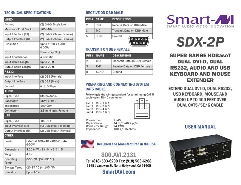
Pair 1 Pins 1 & 2
Pair 2 Pins 3 & 6
Pair 3 Pins 4 & 5
Pair 4 Pins 7 & 8
Connectors: RJ-45
Capacitance: 14 pf/ft (46.2 pf/m)
Conductor Gauge: 24 AWG
Impedance: 100 +/- 15 ohms
4 - Pair, (stranded) Foil Shielded
Pre i S Ag t C 6
Prepairing System CAT6 Cable

