1
2
Dedicated in-room
computer (USB 1) Guest laptop (USB 2)
a
Room
control
Guest laptop (USB 3)
Bottom terminal panel
Side laptop terminal panel
52' (16 m) max.
c
m
g
DVI
Audio terminal panel
Speakers
Inside terminal panel (For in-room computer)
Power switch
HDMI
h
VGA
kp
52' (16 m) max.
n
n
g
n
n
e
HDMI
h
c
Remotely managing your
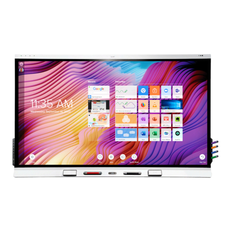
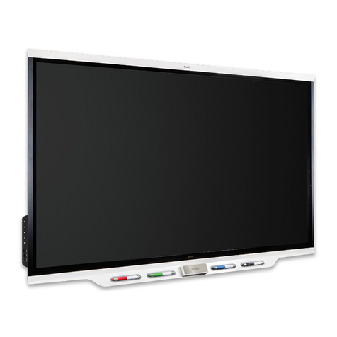
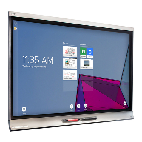
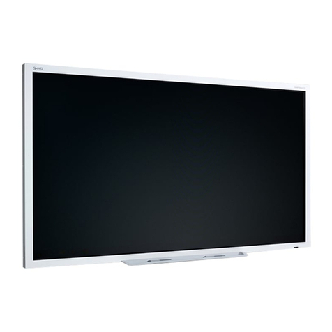
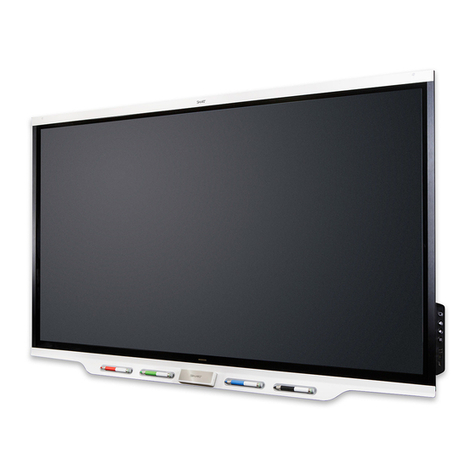
SMART Board™ 8070i
interactive display
Connectingyourinteractive display to anRS-232system 2
Connectiondiagram 2
Serialinterfacesettings3
Powermodes4
RS-232programmingcommandsandresponses 4
Interpretingthe“invalidcmd” response 5
Commandinventory 5
Designatingvideoinput s ourcecommands f ora s pecific video input6
Designatingatarget interactive display 7
Commandsandcontrols 8
Powerstatecommands8
Videoinputs ource 9
Videosourcecommands10
Audiooutputc ommands13
Systeminformationcommands14
Serviceinformation 18
Thisdocumentincludesdet ailedinstructions onhowto s et up your computer orroom control system
toremotelymanage your SMART Board™8070iinteractive display using an RS-232 serial interface.
1
j
SMART Board™ 8070i
InteractiveDisplay
User'sGuide
USB1/USB2 => HDMI/DVI
CopyrightSMART Technologies. All Rights Reserved.Header
Configuringthe video and touch inp utfor your SMA RTBo ard 8070i interactive display
Overview
Youcan connect your SMART Board 8070i interactive di splay to up to three computers at once. Each computer must be conne cted to the interactive
displaywith a USB cable for touc h input and a video cable for video input.
Thefollowing table shows the default touch input and vi deo input pairings.
Ifyou want to use a video and touch input pairing other than the default, y ou can change the video input settings in the Video and Touch Input Settings
windowof the SMART control panel.
NO T E
Ifmultiple interactive displays are connectedto your room computer, disconnect all but one of the interactive displays,and then con figure the interactive
displaysone at a time.
Details
SMARThardware SMARTBoard 8070i interac tive displays
SMARTsoftware SMART Notebook 10.8 SP1 collaborative learning software,SMART Meeting Pro 2.3 so ftware andS MART
ProductDrivers 10.8
Operatingsystems Windows operating systems and Mac OS operat ing system software
Computer Touchinput connection Defaultvideo input connecti on
Roomcomputer USB1 VGA
Guestlaptop USB2 RGB/HV
Sidelaptop USB3 HDMI2
Usingthe computer that’s connecte d to the USB 1 connection, configure the video input for each touc h input connection using the Video and Touch Input
Settingswindow.
IM P O R T ANT
Youmust have the latest version of SMART N otebook software or SMART Meeting Prosoftwa re installedon the computer connec ted to USB 1.
Theinteractive display status lightm ust be green or flashing green.
Theinteractive display cannot be in Eco -Standby mode.
Page1 of 3Configuring the video and touch input for your SMART Board 8070i interactive display (...
2/5/2012http://www.smarttech.com/us/Support/Browse+Support/Support+Documents/KB4/170065.a...
DVI
HDMI
DVI
HDMI
h j
OR OR
OR
1
Extending
USBConnections
SMARTBoard®800 seriesinteractive
whiteboardsand systems
91' (28 m) max.
g
smarttech.com/kb/160469
smarttech.com/kb/170166
smarttech.com/kb/155317
smarttech.com/kb/170157
smarttech.com/kb/170065
smarttech.com/kb/170166
smarttech.com/kb/170166
Alternative cable connections
