manuals.online logo
Brands
  1. Home
  2. •
  3. Brands
  4. •
  5. SMART
  6. •
  7. Measuring Instrument
  8. •
  9. SMART SMART X User manual

SMART SMART X User manual

Other SMART Measuring Instrument manuals

SMART EX500B User manual

SMART

SMART EX500B User manual

SMART S10 User manual

SMART

SMART S10 User manual

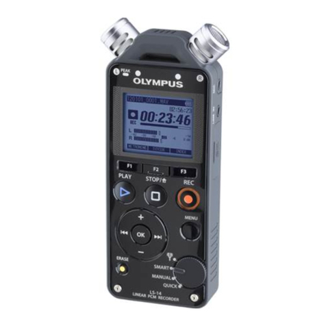
SMART Olympus LS-14 Operating and installation instructions

SMART

SMART Olympus LS-14 Operating and installation instructions

SMART Smartmeter S1 User manual

SMART

SMART Smartmeter S1 User manual

SMART MN586B User manual

SMART

SMART MN586B User manual

SMART SFD11 User manual

SMART

SMART SFD11 User manual

SMART MN520 User manual

SMART

SMART MN520 User manual

SMART Centellis 2000 DC 1.2 User manual

SMART

SMART Centellis 2000 DC 1.2 User manual

SMART MN586 User manual

SMART

SMART MN586 User manual

SMART SMART PE260 User manual

SMART

SMART SMART PE260 User manual

SMART 433-CMU-40 User manual

SMART

SMART 433-CMU-40 User manual

SMART EX505 User manual

SMART

SMART EX505 User manual

SMART EX510 User manual

SMART

SMART EX510 User manual

Popular Measuring Instrument manuals by other brands

Powerfix Profi 278296 Operation and safety notes

Powerfix Profi

Powerfix Profi 278296 Operation and safety notes

Test Equipment Depot GVT-427B user manual

Test Equipment Depot

Test Equipment Depot GVT-427B user manual

Fieldpiece ACH Operator's manual

Fieldpiece

Fieldpiece ACH Operator's manual

FLYSURFER VIRON3 user manual

FLYSURFER

FLYSURFER VIRON3 user manual

GMW TG uni 1 operating manual

GMW

GMW TG uni 1 operating manual

Downeaster Wind & Weather Medallion Series instruction manual

Downeaster

Downeaster Wind & Weather Medallion Series instruction manual

Hanna Instruments HI96725C instruction manual

Hanna Instruments

Hanna Instruments HI96725C instruction manual

Nokeval KMR260 quick guide

Nokeval

Nokeval KMR260 quick guide

HOKUYO AUTOMATIC UBG-05LN instruction manual

HOKUYO AUTOMATIC

HOKUYO AUTOMATIC UBG-05LN instruction manual

Fluke 96000 Series Operator's manual

Fluke

Fluke 96000 Series Operator's manual

Test Products International SP565 user manual

Test Products International

Test Products International SP565 user manual

General Sleep Zmachine Insight+ DT-200 Service manual

General Sleep

General Sleep Zmachine Insight+ DT-200 Service manual

Sensa Core Lacto Spark user manual

Sensa Core

Sensa Core Lacto Spark user manual

VOLTCRAFT UTS-1980 operating instructions

VOLTCRAFT

VOLTCRAFT UTS-1980 operating instructions

EBCHQ 94915 Operation manual

EBCHQ

EBCHQ 94915 Operation manual

Balluff BIP LD2-T017-01-EP-S4 Series user guide

Balluff

Balluff BIP LD2-T017-01-EP-S4 Series user guide

Pulsar IMP Lite Series instruction manual

Pulsar

Pulsar IMP Lite Series instruction manual

ETCR 6800 user manual

ETCR

ETCR 6800 user manual

manuals.online logo
manuals.online logoBrands
  • About & Mission
  • Contact us
  • Privacy Policy
  • Terms and Conditions

Copyright 2025 Manuals.Online. All Rights Reserved.

4
Power OK
WAN OK*
WiFi OK*
3G/4G OK*
Wired connexion
WAN port
3G/4G connexion
SIM card
Power port
3G drive
Power port
Wired connexion
3G OK
(solid blue)
Power OK
WAN OK*
WiFi OK*
Internet OK*
*Solid: connected, Blinking: connected + data transfer in progress
COMMUNICATION
Plug in the Smart Router close to the Smart X installed
(fig. I or J according to the equipment provided. A multi-
socket adaptor may be necessary).
For a wired communication, connect the Smart Router to
the local network (WAN port).
After 2 minutes, the Smart X in the same electrical room
pair automatically to the Smart Router (Wi-Fi).
- LAN: Before the installation, please provide an Ethernet cable and
check with your IT department for outgoing connection authorisation
to our server :
- ICMP protocol to 8.8.8.8 (ping), DNS
- TCP protocol to 178.33.106.9, port 80 (HTTP)
- 3G/4G: If 3G/4G coverage is insufficient (< -100 dBm), it is possible to
move the 3G/4G receiver. Contact Smart Impulse.
OR
Once the installation is completed, please fill in the
installation certificate in order to validate the compliance
and correct operation of the installation and send it within
24 hours to technique@smart-impulse.com imperatively
with the requested photographs. The installation will only
be validated upon receipt of these documents. Thank you!
INSTALLATION VALIDATION
Fig. I
Fig. J
OR
SMART X®
Quick Start Guide
ENGLISH V4.2
Help Desk
+44 (0) 330 684 6080
[email protected]
Full user manual and video tutorial
http://doc.smart-impulse.com
POWER
Depending on your installation (network wiring fig.E):
> For optimum accuracy, first connect the 3-phase lead to
the Smart X then insert the magnetic connectors on the
screws downstream the closest low voltage modular
circuit breaker, while respecting the positioning of the
neutral and the order of the phases.
(fig. F, max voltage 435 VRMS, neutral first).
> OR, for a measurement without opening the electrical
panel, first connect the single-phase lead to the Smart X
then plug it into an outlet of the measured network (fig. G).
> If a Smart X is already installed, you can connect to it via
the ‘bridge’ lead (fig. H, 3 Smart X max).
The screen of the Smart X lights up.
3
Connect first the lead (three- or single-phase) to the ‘IN’
port of the Smart X, then to the network. ‘OUT’ port is
strictly dedicated to sharing power supply between Smart X
via the ‘bridge’ lead (fig. H, forbidden in single-phase or Δ ‘delta’)
Fig. G
Fig. F
Fig. H
Fig. E
2
STEP
1
STEP
2
STEP
OR
Cable hanging
down (neutral to the left)
1
STEP
2
STEP
1
STEP
3 Smart X max.
Forbidden in single-phase or Δ Delta configurations.
N (blue)
L1-R (green)
L2-S (yellow)
L3-T (red)
OR
Neutral 1st.
Respect the order of the phases.
MEASUREMENT
For each phase of the installation to be measured (eg:
main incomer, specific circuit), encircle all the insulated
conductors* thanks to the openable coils (fig. C-D),
by imperatively respecting the direction of the sensors
(colored arrow outside the loop, pointing from the source
to the measured load) and the order of the phases.
The loops must be spaced from each other, fixing them
using the supplied clamping clips (green, yellow, red) to
position on the “ears” of the sensor.
2
To ensure a valid measurement, the sensor loops must
encircle only the conductor(s) to be measured and not be
intertwined.Each coil must be correctly locked (visible
hole) and not twisted (fig. C).
Fig. D
Adhesive mounting bases + clamping clips
1st at 5 cm from the current adapter
‘Clip’
L1-R (green)
L2-S (yellow)
L3-T (red)
‘Clip’
Once the measurement validated (see installation
certificate), seal the sensors using the provided seals.
Source
Load
Coil well locked
and not twisted
= visible hole
Fig. C
Notes:
•* Otherwise, it is possible to measure a part of these conductors
(same number of conductors measured for each phase). Indicate it
imperatively in the installation certificate.
•If the electrical panel supplies a capacitor bank or has downstream
power generation units, it is necessary to measure each of these
points independently thanks to a multi-sensor kit (sold separately,
contact Smart Impulse).
•To disconnect a sensor from the current adapter, press the locking
clip and pull while holding the coloured plastic part of the connector
on the adapter side.
•To disconnect the current adapter from the Smart X (off mode),
press the locking clip using insulated flat screwdriver.
Then connect the current adapter to the Smart X then
connect each coil to the adapter (respect color matching)
while holding the plastic part of the connector until you
hear the connection ‘clip’ (without forcing).
Install the adhesive bases provided along the cables in
order to strengthen the installation and not put too much
strain on the connections (fig. D, 1st at 5 cm max from the
current adapter).
Small pin up,
Big pin down Visible hole
Source
Load
Insertion of
the clamping
clip
Example of loops
spaced from each other
Insertion of the
sensor seal
in the hole
SETUP
The Smart X is a new generation meter compatible with all
electrical configurations (CAT III 300 V) that enables to
identify the consumption of each type of equipment in a
building by measuring a single point of the network.
Magnetic, you can fix it on any metal surface (fig. A) or on
a DIN rail thanks to the adapters provided (fig. B).
For optimum accuracy, connect the Smart X to the the
closest low voltage modular three-phase circuit breaker
(fig. F). If no circuit breaker is accessible, you can
alternatively power it directly from a power outlet.
In this case, the voltages of the unmeasured phases will
be estimated.
1
Down
OR
Fig. A
Fig. B
Power connectors IN/OUT facing down
Metal surface
Smart X
Smart X
DIN rail
Adapters x2
(up then down)
Lower part