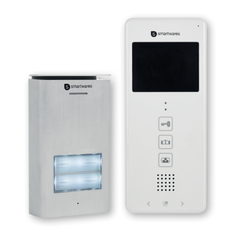
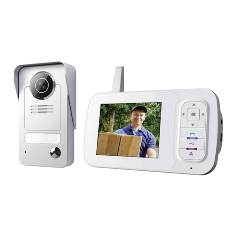
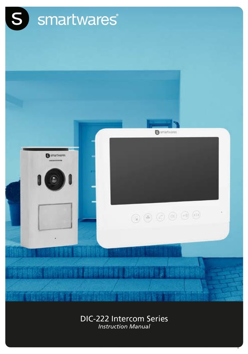
Smartwares VD36W User manual

VD36W

2
VD36W
Instruction manual
Bedienungsanleitung
Gebruiksaanwijzing
Mode d’emploi
Manual de usuario
Manuele utente
Instrukcja obsługi
Návod na použití
Bruksanvisning
Kullanma Talimatları
EN
DE
NL
FR
ES
IT
PL
CZ
SV
TR
....................................................................................................................4.
...............................................................................................................13.
................................................................................................................23.
.......................................................................................................................33.
..................................................................................................................43.
......................................................................................................................53.
....................................................................................................................63.
....................................................................................................................73.
........................................................................................................................83.
................................................................................................................93.
x2 x2
x2 x2

3

4
x2 x2
EN
WARNING
1. Please read these instructions carefully before installing and using the product.
2. Do not cut the power supply cable to extend it; the transformer will not operate with a longer cable. Do not plug
in the transformer until all the wiring has been finished.
3. This product is not a toy. Keep it out of reach of children.
4. Do not operate electrically powered products in explosive atmospheres, such as in the presence of flammable
liquids, gases, or dust. Electrically powered products create sparks which may ignite the dust or fumes.
5. The warnings, precautions, and instructions discussed in this instruction manual cannot cover all possible
conditions and situations that may occur. It must be understood by the operator that common sense and caution
are factors which cannot be built into this product, but must be supplied by the operator.
6. Do not expose the Power Adapter of this product to rain or wet conditions. Water entering the Power Adapter will
increase the risk of electric shock.
7. Do not abuse the Power Cord. Never use the cord for unplugging the plug from the outlet. Keep cord away from
heat, oil, sharp edges or moving parts. Damaged or entangled cords increase the risk of electric shock.
8. The adapter must match the outlet. Never modify the plug in any way. Unmodified plugs and matching outlets
will reduce risk of electric shock.
INCLUDED IN THE PACK:

5
1
10
11
14
13
12
2
3
4
5
6
7
8
9
15
16
18
17
1
6
7
3
4
2
5
8
1. Charging LED
2. Screen
3. Intercom button
4. Exit Button
5. Up button
1. Rain cover
2. Night vision light
3. Microphone
4. Call button
15. Speaker
16. Battery box
17. DC in
18. Outdoor battery charger
6. Left button
7. Monitor / Delete
button
8. Down button
9. Microphone
10. Unlock button
5. Light sensor
6. Camera lens
7. Speaker
8. Connector box
11. Power on/off
12. Photo/confirm button
13. Right button
14. Playback/Set button
EN
KEY FEATURES
INDOOR MONITOR
OUTDOOR INTERCOM

6
Li-ion Rechargeable Battery
3
2
1
3
4
5
2
6
INSTALL & SETUP
Always test the product in location before installation. Be aware that different materials in between the Outdoor
Intercom and Indoor Monitor will affect the operating performance of the product. Follow the Wiring
and pairing guides to test the product. Install the Outdoor Intercom in a dry location if possible.
Mount the Intercom at a suitable height and position to allow the camera to see the visitor.
BATTERY INSTALLATION:
Outdoor Intercom
1. On the side of the Outdoor Intercom there is a battery compartment. Slide the cover open by pushing it up.
2. Insert the battery pack into the holder making sure it is inserted correctly with the“Li-ion rechargeable battery”text
facing the front, please see image.
3. Slide the cover down and“Click” into position.
Indoor Monitor
1. On the back of the Indoor Monitor open the battery cover (16) by sliding it down.
2. Insert the battery pack into the holder making sure it is plugged in correctly. Please see image.
3. Slide the battery cover up and “Click”in position.
1. Select the location for the Outdoor Intercom and using the rain cover as a template mark and drill the holes to
allow the supplied wall plugs to be fitted. (fig 1)
2. Also mark and drill the hole required for the power cables to go through the wall. (fig 2)
3. Push the power cables from the inside of the wall so they are visible on the outside. (fig 3)
4. Stick the sealing pad on the inside of the rain cover. (fig 4)
5. Secure the rain cover into position using the fixings supplied. Pay attention to the angle bracket (fig 5) on the
bottom fixing making sure the power cables are pushed through the back plate seal hole on the bottom right.
6. Secure the power cables into the Intercom as per the wiring diagrams below.
7. Insert the intercom top first into the rain cover and put the bottom into position over the angle bracket.
8. Secure the intercom into position on the rain cover using the securing screw. (fig 6)
WALL MOUNTING
EN

7
OPTIONAL:
TO DOOR LOCK
POWER
SUPPLY
T
12V 1Amp MAX
WIRING
Outdoor Intercom
1. Connect the DC power supply to the terminals marked + & - making sure the wires are installed the correct way
around (See image above).
2. If required connect the door lock cables to the 2 terminals making sure a suitable power supply is used to power
the door lock.
(Items DB5005 and DB5005L - Not supplied)
Indoor Monitor
1. Connect the USB lead to the Indoor Monitor base, plug the adaptor into a wall outlet and switch
the wall outlet ON.
EN

8
SCREEN ICONS
1. Press the power button (11) to turn on the screen.
2. Hold the button (3) for 3 seconds and the screen will display “pairing”.
3. Press the CALL button (4) once on the Outdoor Intercom to turn it on.
4. HOLD the CALL button (4) for 10 seconds on the Outdoor Intercom.
5. “Success”will be displayed on the Monitor to indicate pairing is complete.
6. If pairing did not work then “fail”will be displayed, please repeat step 2, 3 + 4 again.
Outdoor Intercom
1. When a visitor presses the call button (4) of outdoor intercom, the indoor monitor will give a bell tone and activate
the monitor screen. The indoor monitor screen will display a picture of the visitor automatically.
2. Press the Intercom button (3) and speak to the visitor.
3. Press the Exit button (4) to end the call and the screen will switch to standby mode.
Indoor Monitor:
1. The Monitor/Delete button (7) can be used to see who is at the door when the Outdoor CALL button has
not been pressed. (Only available when outdoor intercom is mains powered.)
2. Press the Intercom button (3) and speak to the visitor.
3. Press the Exit button (4) and the screen will switch to standby mode.
Unlock:
1. After identifying the visitor press the Unlock button (10) to unlock the door. (Only for operation with an
electric door opener MAX 12v 1A using separate power supply - Items DB5005 and DB5005L - Not supplied.)
PAIRING
EN

9
Photograph
1. When a visitor presses the call (4) button of the Outdoor Intercom the Indoor Monitor will automatically take a photo.
2. On the Indoor Monitor press the Photo/Confirm button (12) and it will take an extra photo of the visitor.
View / delete photo:
1. On the Indoor Monitor press the Playback/Set button (14) to enter the picture menu.
2. Press the Up (5) or Down (8) buttons to view the stored photo.
3. Press the Monitor/Delete (7) button to enter delete dialog box.
4. Press the Left (6) or Right (13) button to select Yes / No.
5. Press the Photo/Confirm (12) button to confirm.
6. Press the Exit (4) button to exit.
To delete all photos:
1. On the Indoor Monitor press the Playback/Set button (14) to enter the picture menu.
2. Hold the Monitor/Delete (7) button for 3 seconds and“delete all”will appear.
3. Press the Left (6) or Right (13) button to select Yes / No.
4. Press the Photo/Confirm (12) button to confirm.
5. Press the Exit (4) button to exit.
Setting the time / Date:
1. Hold down the Playback/Set button (14) for 3 seconds to enter the main menu.
2. Press the Up (5) or Down (8) buttons to move through the menu options to time/date.
3. Press the Photo/Confirm button (12) to enter the submenu.
4. Press the Up (5) or Down (8) buttons to adjust the settings.
5. Press the Left (6) or Right (13) button to move through the time/date options.
6. Press the Photo/Confirm button (12) to save and exit.
7. Press the Exit (4) button to exit.
Adjust the Monitor brightness:
1. Hold down the Playback/set button (14) for 3 seconds to enter the main menu.
2. Press the Up (5) or Down (8) buttons to move through the menu options to brightness.
3. Press the Photo/Confirm button (12) to enter the submenu.
4. Press the Up (5) or Down (8) buttons to select the level.
5. Press the Photo/Confirm button (12) to save and exit.
6. Press the Exit (4) button to exit.
Adjust the ring volume:
1. Hold down the Playback/Set button (14) for 3 seconds to enter the main menu.
2. Press the Up (5) or Down (8) buttons to move through the menu options to volume.
3. Press the Photo/Confirm button (12) to enter the submenu.
4. Press the Up (5) or Down (8) buttons to select the level.
5. Press the Photo/Confirm button (12) to save and exit.
6. Press the Exit (4) button to exit.
Setting the bell tone:
1. Hold down the Playback/Set button (14) for 3 seconds to enter the main menu.
2. Press the Up (5) or Down (8) buttons to move through the menu options to chime.
3. Press the Photo/Confirm button (12) to enter the submenu.
4. Press the Up (5) or Down (8) buttons to select the tone.
5. Press the Photo/Confirm button (12) to save and exit.
6. Press the Exit (4) button to exit.
OPERATION
EN
10
Test the chime before drilling any holes to ensure unit is within operating range.
Wire-free range is affected by some materials/structures. Test prior to installation.
80-95%
90-100%
60-80%
0-20%
120m
WOOD
OPEN A
BRICK
IR
METAL
RANGE GUIDE
EN

11
TECHNICAL SPECIFICATIONS
SPECIFICATION
Operating Frequency 2400-2483.5MHz
Transmission rate 15-25fps (only for effective distance)
Open field operating range 120m
TX power 14 – 18dBm
RX sensitivity -85dBm
Operating Temperature -10°c - +50°c
Storage Temperature -20°c - +60°c
Operating Humidity ≤85% RH
OUTDOOR CAMERA
Image sensor type CMOS
View Angle 55°
Supply Voltage DC 5V 1A
Consumption Current 250mA (± 50mA)
Charging time Around 5 hours
Battery 3.7v 1500mAH
Adaptor IP: 240v OP: 5v 1A
INDOOR MONITOR
Screen size 2.4”
Resolution 320 x 240 (RGB)
Supply Voltage DC 5V 1A
Consumption current 350mA (± 50mA)
Charging time Around 5 hours
Image format JPEG
Battery 3.7v 1200mAH
Adaptor IP: 240v OP: 5v 1A
80-95%
90-100%
60-80%
0-20%
120m
WOOD
OPEN A
BRICK
IR
METAL
80-95%
90-100%
60-80%
0-20%
120m
WOOD
OPEN A
BRICK
IR
METAL
EN

12
Conforms to all relevant European Directives.
Smartwares declares that the appliance, model [VD36W], complies
with the main essential requirements of the R&TTE directive,
1999/5/CE. The complete declaration of conformity is available
on request at:
These symbols indicate that this product must not be disposed of with other
household rubbish in the EU. In order to avoid all damage to the environment
or to human health with rogue disposal responsibly recycle this product in order
to encourage reuse of the materia resources. To return you used device,
please use collection and return systems, or contact the dealer where
you bought this product. He will take the product in rder to protect the
environment.
SAFETY INFORMATION
PRECAUTION
Do not cover the ventilation openings with objects such as newspaper, table cloths, curtains, etc.
Do not allow this product to get directly into contact with heat sources or naked flames.
The normal operation of the product may be disturbed by strong electro-magnetic interference.
This equipement is built exclusively for a domestic use.
The device must not be exposed to splashes and it must not be submerged.
No object containing liquids, such as a vase, may be placed on the device.
Maintain a minimum safety distance of 10cm all around the product in order to insure proper ventilation.
Insure the doorbell push button is not installed where it may be covered by water or rain.
Do not allow children to play with the device.
WARNING ABOUT BATTERIES
Only an adult may replace and install batteries.
Remove used batteries from this device.
Do not dispose of batteries in fire,they may explode or leak.
Do not short-circuit battery terminals.
DO not use any other type of battery other than the rechargeable pack supplied or similar.
Do not allow this device to get directly into contact with heat sources or flames.
Do not allow water to enter into contact with the batteries or the wires.
Install with caution to avoid damaging the batteries.
During battery installation in their compartment, insure proper polarity (+)/ (-).
Only use recommended batteries.
Remove the batteries if the device remains unused for long periods.
Keep the device away from small children.
Keep the unused batteries in their original packaging.
At the end of its life, this product must be returned to a waste processing center in order to extract the
batteries.
EN

13

14
x2 x2
WANRNHINWEISE
1. Bitte lesen Sie diese Anleitung sorgfältig, bevor Sie dieses Produkt installieren und in Betrieb nehmen.
2. Zerschneiden Sie das Netzkabel nicht, um es zu verlängern; der Transformator funktioniert nicht mit einem
längeren Kabel. Schließen Sie den Transformator erst an, wenn die Verkabelung vollständig durchgeführt wurde.
3. Dieses Produkt ist kein Spielzeug. Bewahren Sie es außerhalb der Reichweite von Kindern auf.
4. Verwenden Sie elektrische Geräte nicht in explosiver Umgebung, wie in der Nähe von entflammbaren
Flüssigkeiten, Gasen oder Staub. Elektrische Produkte können Funken erzeugen, die den Staub oder die Gase
entzünden können.
5. Die in dieser Anleitung erwähnten Warnungen, Vorsichtsmaßnahmen und Anweisungen können nicht alle
Bedingungen und Situationen abdecken, die möglicherweise auftreten können. Der Benutzer muss verstehen,
dass gesunder Menschenverstand und Vorsicht Faktoren sind, die nicht in dieses Produkt eingebaut werden
können, sondern vom Benutzer selbst mitgebracht werden müssen.
6. Setzen Sie das Netzteil dieses Produktes nicht Regen oder Nässe aus. Wenn Wasser in das Netzteil eindringt,
erhöht sich die Gefahr eines Stromschlags.
7. Verwenden Sie das Netzkabel nicht falsch. Ziehen Sie niemals damit den Stecker aus der Steckdose. Halten Sie
das Kabel fern von Hitze, Öl, scharfen Kanten oder beweglichen Teilen. Beschädigte oder verhedderte Kabel
vergrößern die Gefahr eines Stromschlags.
8. Das Netzteil muss zur Steckdose passen. Nehmen Sie keine Veränderungen am Stecker vor Durch Originalstecker
und passende Steckdosen reduziert sich das Risiko eines Stromschlags.
PACKUNGSINHALT:
DE

15
1
10
11
14
13
12
2
3
4
5
6
7
8
9
15
16
18
17
1
6
7
3
4
2
5
8
1. Lade-LED
2. Display
3. Intercom-Taste
4. Exit-Taste
5. Up-Taste
1. Regenschutz
2. Nachtsicht-Leuchte
3. Mikrofon
4. Ruftaste
15. Lautsprecher
16. Batteriefach
17. DC In (Eingang Gleichstrom)
18. Batterie-Ladegerät für den Außenbereich
6. Links-Taste
7. Monitor- / Lösch-
Taste
8. Down-Taste
9. Mikrofon
10. Türöffner-Taste
5. Lichtsensor
6. Kameraobjektiv
7. Lautsprecher
8. Anschlusskasten
11. Power-Taste
12. Foto-/Bestätigungstaste
13. Rechts-Taste
14. Wiedergabe-/Einstellungstaste
SCHLÜSSELFUNKTIONEN
INNENGERÄT
AUSSENGERÄT
DE

16
Li-ion Rechargeable Battery
3
2
1
3
4
5
2
6
INSTALLATION & EINRICHTUNG
Prüfen Sie das Produkt vor der Installation am Montageort. Unterschiedliche Materialien zwischen Außengerät und
Innengerät beeinflussen die Betriebsleistung des Produktes. Befolgen Sie die Anweisungen unter“Verkabelung und
Pairing”, um das Produkt zu prüfen. Montieren Sie das Außengerät möglichst an einem trockenen Ort.
Montieren Sie das Gerät in geeigneter Höhe und Position, so dass die Kamera den Besucher erfassen kann.
EINSETZEN DER AKKUS:
Außengerät
1. Das Akkufach befindet sich seitlich am Außengerät. Schieben Sie die Abdeckung auf, indem Sie sie nach
oben drücken.
2. Legen Sie den Akku in den Halter; passen Sie auf, dass der Text“Li-Ion Akku”nach vorn schaut, s. Abbildung.
3. Schieben Sie die Abdeckung herunter, bis sie mit einem “Klick”einrastet.
Innengerät
1. Öffnen Sie die Akkufachabdeckung auf der Rückseite des Innengerätes (16), indem Sie sie nach unten schieben.
2. Legen Sie den Akku in den Halter; passen Sie auf, dass er richtig eingelegt ist. S. Abbildung.
3. Schieben Sie die Batteriefachabdeckung herauf, bis sie mit einem“Klick” einrastet.
1. Wählen Sie den Montageort für das Außengerät aus und verwenden Sie dann den Regenschutz als Schablone;
markieren und bohren Sie die Löcher, um die mitgelieferten Dübel einzustecken. (Nr. 1)
2. Markieren und bohren Sie auch das Loch, um die Stromkabel durch die Wand zu führen. (Nr. 2)
3. Schieben Sie die Stromkabel von innen nach außen durch die Wand. (Nr. 3)
4. Kleben Sie die Dichtungsauflage auf die Innenseite des Regenschutzes. (Nr. 4)
5. Sichern Sie den Regenschutz mit den mitgelieferten Befestigungen an der richtigen Position. Beachten Sie den
Haltewinkel (Nr. 5) an der unteren Befestigung und stellen sie sicher, dass die Stromkabel durch das Loch in
der Dichtung der Rückenplatte rechts unten geschoben werden.
6. Sichern Sie die Stromkabel so in der Gegensprechanlage, wie der Schaltplan unten zeigt.
7. Setzen Sie das Gerät mit der Oberseite zuerst in den Regenschutz ein und bringen Sie die Unterseite über dem
Haltewinkel in Position.
8. Sichern Sie die Gegensprechanlage mit der Sicherungsschraube im Regenschutz. (Nr. 6)
WANDMONTAGE
DE

17
OPTIONAL:
TO DOOR LOCK
POWER
SUPPLY
T
12V 1Amp MAX
SCHALTPLAN
Außengerät
1. Schließen Sie das Gleichstrom-Netzteil an die mit + & - markierten Pole an und vergewissern Sie sich, dass die
Drähte richtig herum angeschlossen werden (S. Abbildung oben).
2. Falls erforderlich, schließen Sie die Türschlosskabel an die 2 Pole an und stellen
Sie sicher, dass eine geeignete Stromquelle für die Versorgung des Türschlosses verwendet wird.
(Bauteile DB5005 und DB5005L - Nicht enthalten)
Laden des Innengeräts:
1. Schließen Sie das USB-Kabel an den Sockel des Innengerätes an, stecken Sie das Netzteil in eine Wandsteckdose
und schalten Sie die Wandsteckdose ein (falls erforderlich).
DE

18 DE
SYMBOLE AUF DEM DISPLAY
1. Drücken Sie die Power-Taste (11), um das Display einzuschalten.
2. Halten Sie die -Taste (3) 3 Sekunden lang gedrückt; das Display zeigt“Pairing” an.
3. Drücken Sie die RUF-Taste (4) am Außengerät einmal, um es einzuschalten.
4. HALTEN Sie die RUF-Taste (4) am Außengerät 10 Sekunden lang gedrückt.
5. “Erfolg”erscheint auf dem Monitor, um anzuzeigen, dass das Pairing abgeschlossen ist.
6. Falls das Pairing nicht erfolgreich war wird “fehlgeschlagen” angezeigt; bitte wiederholen Sie Schritte 2, 3 + 4.
Außengerät
1. Wenn ein Besucher die Ruftaste (4) des Außengerätes drückt, ertönt vom Innenmonitor ein Klingelton und das
Display wird aktiviert. Der Bildschirm des Innenmonitors zeigt automatisch ein Bild des Besuchers.
2. Drücken Sie auf die -Taste (3) und sprechen Sie mit dem Besucher.
3. Drücken Sie die Exit -Taste (4), um den Anruf zu beenden; das Display schaltet in den Standby-Modus..
Innengerät:
1. Mit der Monitor-/Lösch -Taste (7), kann man sehen wer an der Tür ist, bevor die Ruftaste außen gedrückt
wurde. (Nur verfügbar, wenn das Außengerät mit Netzstrom betrieben wird.)
2. Drücken Sie auf die -Taste (3) und sprechen Sie mit dem Besucher.
3. Drücken Sie die Exit -Taste (4) und das Display schaltet in den Standby-Modus.
Entriegein:
1. Wenn Sie den Besucher identifiziert haben, drücken Sie auf die Türöffnertaste (10), um die Tür zu öffnen. (Nur
für den Betrieb mit einem elektrischen Türöffner mit max. 12V, 1A mit eigener Stromversorgung - Bauteile DB5005
und DB5005L - Nicht enthalten.)
PAIRING
DE

19
DE
Foto
1. When a visitor presses the call (4) button of the Outdoor Intercom the Indoor Monitor will automatically take a photo.
2. On the Indoor Monitor press the Photo/Confirm button (12) and it will take an extra photo of the visitor.
Foto ansehen / löschen:
1. Drücken Sie am Innengerät die Wiedergabe-/Einstellungstaste (14), um zum Fotomenü zu gelangen.
2. Drücken Sie die Up- (5) oder Down- (8)-Tasten, um das gespeicherte Foto anzusehen.
3. Drücken Sie die Monitor-/Löschtaste (7), um zur Dialogbox“löschen”zu gelangen.
4. Drücken Sie die Links- (6) oder Rechts- (13)-Taste, um Ja / Nein auszuwählen.
5. Drücken Sie zur Bestätigung die Foto-/Bestätigungstaste (12).
6. Drücken Sie die Exit-Taste (4) zum Beenden.
Alle Fotos löschen:
1. Drücken Sie am Innengerät die Wiedergabe-/Einstellungstaste (14), um zum Fotomenü zu gelangen.
2. Halten Sie die Monitor-/Löschtaste (7) 3 Sekunden lang gedrückt; es erscheint “alles löschen”.
3. Drücken Sie die Links- (6) oder Rechts- (13)-Taste, um Ja/Nein auszuwählen.
4. Drücken Sie zur Bestätigung die Foto-/Bestätigungstaste (12).
5. Drücken Sie die Exit-Taste (4) zum Beenden.
Zeit / Datum einstellen:
1. Halten Sie die Wiedergabe-/Einstellungstaste (14), 3 Sekunden lang gedrückt, um zum Hauptmenü zu gelangen.
2. Drücken Sie die Up- (5) oder Down- (8)-Tasten, um durch die Menüoptionen zu blättern, bis Sie zu Zeit/Datum kommen.
3. Drücken Sie die Foto-/Bestätigungs -Taste (12), um zum Untermenü zu gelangen.
4. Drücken Sie die Up- (5) oder Down- (8)-Tasten, um die Einstellung vorzunehmen.
5. Drücken Sie die Links- (6) oder Rechts- (13) Taste, um durch die Optionen für Zeit/Datum zu blättern.
6. Drücken Sie die Foto-/Bestätigungstaste (12) zum Speichern und Beenden.
7. Drücken Sie die Exit-Taste (4) zum Beenden.
Die Helligkeit des Displays einstellen:
1. Halten Sie die Wiedergabe-/Einstellungstaste (14), 3 Sekunden lang gedrückt, um zum Hauptmenü zu gelangen.
2. Drücken Sie die Up- (5) oder Down- (8)-Tasten, um durch die Menüoptionen zu blättern, bis Sie zur Helligkeit kommen.
3. Drücken Sie die Foto-/Bestätigungs -Taste (12), um zum Untermenü zu gelangen.
4. Drücken Sie die Up- (5) oder Down- (8)-Tasten, um die Helligkeit auszuwählen.
6. Drücken Sie die Foto-/Bestätigungstaste (12) zum Speichern und Beenden.
7. Drücken Sie die Exit-Taste (4) zum Beenden.
Klingellautstärke einstellen:
1. Halten Sie die Wiedergabe-/Einstellungstaste (14), 3 Sekunden lang gedrückt, um zum Hauptmenü zu gelangen.
2. Drücken Sie die Up- (5) oder Down- (8)-Tasten, um durch die Menüoptionen zu blättern, bis Sie zur Lautstärke kommen.
3. Drücken Sie die Foto-/Bestätigungs -Taste (12), um zum Untermenü zu gelangen.
4. Drücken Sie die Up- (5) oder Down- (8)-Tasten, um die Lautstärke auszuwählen.
5. Drücken Sie die Foto-/Bestätigungstaste (12) zum Speichern und Beenden.
6. Drücken Sie die Exit-Taste (4) zum Beenden.
Setting the bell tone:
1. Halten Sie die Wiedergabe-/Einstellungstaste (14), 3 Sekunden lang gedrückt, um zum Hauptmenü zu gelangen.
2. Drücken Sie die Up- (5) oder Down- (8)-Tasten, um durch die Menüoptionen zu blättern, bis Sie zum Klingelton kommen.
3. Drücken Sie die Foto-/Bestätigungs -Taste (12), um zum Untermenü zu gelangen.
4. Drücken Sie die Up- (5) oder Down- (8)-Tasten, um den Ton auszuwählen.
5. Drücken Sie die Foto-/Bestätigungstaste (12) zum Speichern und Beenden.
6. Drücken Sie die Exit-Taste (4) zum Beenden.
BEDIENUNG
DE

20 DE
Testen Sie die Türglocke, bevor Sie Löcher bohren, um sicherzustellen, dass sich das Gerät im Betriebsbereich befindet.
Die Reichweite von Funkgeräten wird von Materialien/Strukturen beeinflusst. Vor der Montage testen.
80-95%
90-100%
60-80%
0-20%
120m
WOOD
OPEN A
BRICK
IR
METAL
HINWEIS ZUR REICHWEITE
Other manuals for VD36W
2
Table of contents
Languages:
Other Smartwares Intercom System manuals

Smartwares
Smartwares DIC-21102 User manual

Smartwares
Smartwares DIC-222 Series User manual

Smartwares
Smartwares DIC-224 Series User manual

Smartwares
Smartwares DIC-24112 User manual

Smartwares
Smartwares DIC-22815 User manual

Smartwares
Smartwares DIC-211 Series User manual

Smartwares
Smartwares DIC-221 series User manual

Smartwares
Smartwares VD38W User manual

Smartwares
Smartwares VD36W User manual

Smartwares
Smartwares DIC-221 series User manual