manuals.online logo
Brands
  1. Home
  2. •
  3. Brands
  4. •
  5. SMC Networks
  6. •
  7. Controllers
  8. •
  9. SMC Networks ITV0000 Series User manual

SMC Networks ITV0000 Series User manual

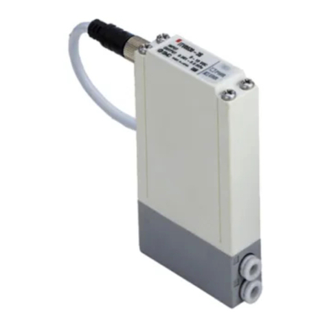
For the stepless control of air pressure in
proportion to electrical signals
Applicable Fieldbus protocols
compatible
products have
been added.
Serial communication specification
*1 Values for the communication type (PROFIBUS DP)
Compact and lightweight
(Integrated communication parts)
Weight: 350 g*1
(ITV1000)
Power consumption
: 4W*1
or less
For the ITV10m0-IL
ITV009 mSeries
Electro-Pneumatic Regulators
Electronic Vacuum Regulators
ITV0000 Series ITV1000 Series
NewNew
ITV2000 Series ITV3000 Series
98
50
50
Due to the built-in
communication board,
no converter is required.
ITV209 mSeries
Max. flow rate
6L/min (ANR)
Max. flow rate
1500 L/min (ANR)
Max. flow rate
200 L/min (ANR)
Grease-free specification
(Parts in contact
with fluid)
Max. flow rate
4000 L/min (ANR)
p. 5
p. 13
p. 13 p. 39
p. 13 p. 46
Set pressure: 0.6 MPa Supply pressure: 1.0 MPa
RS-232C specification
Electro-Pneumatic Regulator/
Electronic Vacuum Regulator
ITV Series
CAT.ES60-15G
RoHS
IP65
Electro-Pneumatic Regulator/Electronic Vacuum Regulator ITV Series
Thanks to its simplified high-
density circuit board design,
an extremely compact
product has been made
possible.
Stations can be easily
increased or decreased due
to the DIN rail mounting
design.
Improved space
saving and weight
reduction when
used in a manifold
Flat bracket L-bracket
Electro-Pneumatic Regulator ITV1000/2000/3000 Series
Electronic Vacuum Regulator ITV209mSeries
Compact Electro-Pneumatic Regulator
ITV0000 Series
Compact Vacuum Regulator
ITV009 mSeries
¡Sensitivity: 0.2% F.S. or less
¡Linearity: ±1% F.S. or less
¡Hysteresis: 0.5% F.S. or less
¡
Cable connections in 2 directions
¡Grease-free specification
(ITV1000 series)
¡Application examples
ITV1000 ITV2090ITV2000 ITV3000
For multi-stage control to analog control For electrostatic coating control
100g
15mm
¡Linearity: ±1% F.S. or less
¡Hysteresis: 0.5% F.S. or less
¡Repeatability: ±0.5% F.S. or less
¡High-speed response time: 0.1 s (Without load)
*This is not a guaranteed value as it depends on the operating environment.
¡High stability
Sensitivity: 0.2% F.S. or less
M Built-in One-touch
fittings
M With error indication
LED
M2 types of brackets
M2 types of cable connectors
Reduced wiring
Serial communication specification
Applicable Fieldbus protocols
Air filter
(5 µm or less)
Mist separator
(0.3 µm or less) (0.01 µor less)
IR (Precision regulator)
ITV (Electro-pneumatic regulator)
Straight type Right angle type
Regulators
Solenoid valves
SUP.
OUT.
OUT.
SUP.
Controller
Controller
Electro-pneumatic
regulator
Analog control
Mist
separator
Air filter
SUP.
Controller
Control signal
Coating nozzle
Coating
material
Electro-pneumatic regulator
Air filter
Straight type Right angle type
Compact
Lightweight
p. 39
p. 5
p. 13
p. 46
IP65
IP65 equivalent
RS-232C specification
1
IO-Link Compatible Devices:
Electro-Pneumatic Regulator ITV10m0/20m0/30m0-IL
Electronic Vacuum Regulator ITV2090-IL
IO-Link communication enables users to check
device information and monitor device status in
addition to performing pressure control.
IO-Link master
Process Data
IO-Link communication
Application
VFor the manufacturing of various products
The set pressure analog value can be
changed to control the indentation
pressure applied to each workpiece.
This allows for a variety of products to
be manufactured on the same line.
IO-Link Compatible Devices:
Electro-Pneumatic Regulator
ITV10m0/20m0/30m0-IL
Electronic Vacuum Regulator
ITV2090-IL
Configuration File (IODD File*1)
·Manufacturer ·Product part no. ·Set value
*1 IODD File:
IODD is an abbreviation of IO Device
Description. This file is necessary for setting
the device and connecting it to a master. Save
the IODD file on the PC to be used to set the
device prior to use.
Implement diagnostic bits in the
process data.
The diagnostic bit in the cyclic process data makes it easy to find problems with the
equipment.
It is possible to find problems with the equipment in real time using the cyclic (periodic)
data and to monitor such problems in detail with the noncyclic (aperiodic) data.
Diagnosis items
· Output pressure is within the set pressure ±10%
· Notification of energizing time
· Residual pressure error
· Target value over range
· Pressure under range (LLL)
· Pressure over range (HHH)
· Power supply voltage drop
· Excessive power supply voltage
· Warning occurred
· Internal communication error
<PD_IN: 4 bytes>
Byte 0 1
Bit 31 30 29 28 27 26 25 24 23 22 21 20 19 18 17 16
Value Output pressure value (16 bits)
Byte 2 3
Bit 15 14 13 12 11 10 9 8 7 6 5 4 3 2 1 0
Value Abnormal Warning Notification SSC1
<PD_OUT: 2 bytes>
Byte 0 1
Bit 15 14 13 12 11 10 9 8 7 6 5 4 3 2 1 0
Value Set pressure value (16 bits)
PLC PC
Various fieldbusses
IO-Link is an open communication inter-
face technology between the sensor/actu-
ator and the I/O terminal that is an interna-
tional standard: IEC 61131-9.
The IO-Link master and device can be
connected with one cable.
Uses 4-wire unshielded cables
Only a single cable combining the communication
wire and the power supply wire is required.
Special communication cables are not necessary.
A conventional 4-wire unshielded cable can be used for the
input and output of sensors, switches, etc.
(Recommended specifications: Conductor resistance 3 Ω,
Wire-to-wire capacitance 3 nF or less, 20 m or less)
p. 13
p. 46
2
Electro-Pneumatic Regulator/Electronic Vacuum Regulator ITV Series
Series Model
Set pressure range
Input signal Port size Page
Electro-Pneumatic Regulators
ITV0000 Series ITV001m0.001 to 0.1 MPa
Current type: 4 to 20 mADC
(Sink type)
Current type: 0 to 20 mADC
(Sink type)
Voltage type: 0 to 5 VDC
Voltage type: 0 to 10 VDC
Built-in One-touch
fittings
Metric size: ø4
Inch size: ø5/32
5
ITV003m0.001 to 0.5 MPa
ITV005m0.001 to 0.9 MPa
ITV1000 Series ITV101m0.005 to 0.1 MPa
Current type: 4 to 20 mADC
(Sink type)
Current type: 0 to 20 mADC
(Sink type)
Voltage type: 0 to 5 VDC
Voltage type: 0 to 10 VDC
Preset input
(4 points/16 points)
10-bit digital input
CC-Link compatible
DeviceNet™ compatible
PROFIBUS DP compatible
IO-Link compatible
RS-232C communication
1/8, 1/4 13
ITV103m0.005 to 0.5 MPa
ITV105m0.005 to 0.9 MPa
ITV201m0.005 to 0.1 MPa
1/4, 3/8 13
ITV203m0.005 to 0.5 MPa
ITV205m0.005 to 0.9 MPa
ITV3000 Series ITV301m0.005 to 0.1 MPa
1/4, 3/8, 1/2 13
ITV303m0.005 to 0.5 MPa
ITV305m0.005 to 0.9 MPa
Electronic Vacuum Regulators
ITV009mSeries
ITV009m−1 to −100 kPa
Current type: 4 to 20 mADC
(Sink type)
Current type: 0 to 20 mADC
(Sink type)
Voltage type: 0 to 5 VDC
Voltage type: 0 to 10 VDC
Built-in One-touch
fittings
Metric size: ø4
Inch size: ø5/32
39
ITV209mSeries
ITV209m−1.3 to −80 kPa
Current type: 4 to 20 mADC
(Sink type)
Current type: 0 to 20 mADC
(Sink type)
Voltage type: 0 to 5 VDC
Voltage type: 0 to 10 VDC
Preset input
(4 points/16 points)
10-bit digital input
CC-Link compatible
DeviceNet™ compatible
PROFIBUS DP compatible
IO-Link compatible
RS-232C communication
1/4 46
Series Variations For the stepless control of air pressure in proportion to electrical signals
ITV2000 Series
3
Electro-Pneumatic Regulator/Electronic Vacuum Regulator ITV Series
Electro-Pneumatic Regulators
MITV0000 Series
How to Order p. 5
Specifications p. 6
Accessories (Option) p. 6
Working Principle p. 7
Linearity/Hysteresis, Repeatability, Pressure Characteristics, Flow Rate Characteristics
p. 8
Dimensions p. 10
MITV1000/2000/3000 Series
How to Order p. 13
Standard Specifications p. 14
Communication Specifications p. 14
Modular Products and Accessory Combinations p. 15
Accessories (Option)/Part Nos. p. 15
Working Principle p. 16
Linearity, Hysteresis, Repeatability, Pressure Characteristics, Flow Rate Characteristics, Relief Flow Characteristics
p. 17
Construction p. 23
Dimensions p. 25
Made to Order p. 34
Electronic Vacuum Regulators
MITV009mSeries
How to Order p. 39
Specifications p. 40
Accessories (Option) p. 40
Working Principle p. 41
Linearity/Hysteresis, Repeatability, Pressure Characteristics, Flow Rate Characteristics
p. 42
Dimensions p. 43
MITV2090/2091 Series
How to Order p. 46
Standard Specifications p. 47
Communication Specifications p. 47
Working Principle p. 48
Linearity, Hysteresis, Repeatability, Pressure Characteristics, Flow Rate Characteristics
p. 48
Dimensions p. 49
Accessories (Option) p. 52
Specific Product Precautions p. 53
CONTENTS
4
ITV0000
Electro-Pneumatic RegulatorsElectronic Vacuum Regulators
ITV1000/2000/3000ITV009ITV2090/2091
Specific Product
Precautions Accessories
RoHS
How to Order
For single unit and single unit for manifold
ITV00 1 0 0 N
Cable connector (Option)
Bracket/Option for single unit only
Base type
Pressure range
Built-in One-touch fittings type
Input signal
Power supply voltage
Manifold
IITV00 02 n
Stations
Option
For single unit
For manifold
*A DIN rail with the length specified by the number of stations is
attached to the manifold. For dimensions of the DIN rail, refer to
the external dimensions.
How to Order Manifold Assembly (Example)
If a DIN rail longer than
the specified stations is
required, specify the
applicable stations in
two digits.
(Max. 10 stations)
Example) IITV00-05-07
IITV00-03
········
1 set (Manifold part no.)
*
ITV0030-3MS······2 sets (Electro-pneumatic regulator part no. (Stations 1, 2))
*
ITV0030-3ML······1 set (Electro-pneumatic regulator part no. (Station 3))
Indicate the part numbers of electro-pneumatic regulators to be mounted
below the manifold part number.
Example)
Due to the common supply/exhaust feature, note that different pressure
range combinations are not available.
Indicate part numbers in order starting from the first station on
the D side.
Caution) Combination with having different pressure ranges is not
available due to common supply/exhaust features.
The asterisk denotes the symbol for the assembly. Prefix it to the part
numbers of the electro-pneumatic regulator.
One-touch fitting size for supply/
exhaust parts (End plate)
Compact Electro-Pneumatic Regulator
ITV0000 Series
10.1 MPa
30.5 MPa
50.9 MPa 024 VDC ±10%
112 to 15 VDC
0Current type 4 to 20 mADC (Sink type)
1Current type 0 to 20 mADC (Sink type)
2Voltage type 0 to 5 VDC
3Voltage type 0 to 10 VDC
Symbol SUPzOUTxEXHc
Nil Metric size
(Light gray) ø4
UInch size
(Orange) ø5/32"
Symbol SUPzOUTxEXHc
Nil Metric size
(Light gray) ø6 ø4 ø6
UInch size
(Orange) ø1/4" ø5/32" ø1/4"
NWithout cable connector
SStraight type 3 m
LRight angle type 2 m
Nil Without bracket
B
Flat
bracket
C
L-bracket
Nil For single unit
MFor manifold
02 2 stations
03 3 stations
···
···
10 10 stations
Nil ø6 (Light gray)
Uø1/4" (Orange)
DIN rail
ITV0030-3ML
ITV0030-3MS
D side
1 2 3 ···
5
*1 Indicates the weight of a single unit
For IITV00-n
Total weight (g) ≤Stations (n) x 100 + 130 (Weight of end block A, B assembly) + Weight (g)
of DIN rail
*2 When measuring ITV analog output from 1 to 5 VDC, if the load impedance is less than 100
kW, the analog output monitor accuracy of ±6% F.S. or less may not be available.
The product with an accuracy of within ±6% is supplied upon your request.
Output pressure remains unaffected.
*3 When using under the conditions equivalent to IP65, connect the fitting or tube to the
breathing hole before use. (For details, refer to “Specific Product Precautions 1” on page 53.)
*When there is a downstream flow consumption, pressure may become unstable depending on
piping conditions.
*When the input signal is at 0%, the exhaust solenoid valve is controlled to reduce the outlet
pressure to zero. For this reason, a noise may be generated. This noise is normal and does
not indicate a fault.
Specifications
Accessories (Option)
Bracket Cable connector
Flat bracket assembly (including 2 mounting screws)
P39800022
L-bracket assembly (including 2 mounting screws)
Tightening torque when assembling is 0.3 N·m.
P39800023
Straight type
Right angle type
M8-4DSX3MG4
P398000-501-2
Model ITV001mITV003mITV005m
Min. supply pressure Set pressure + 0.1 MPa
Max. supply pressure 0.2 MPa 1.0 MPa
Set pressure range 0.001 to 0.1 MPa 0.001 to 0.5 MPa 0.001 to 0.9 MPa
Power supply
Voltage 24 VDC ±10%, 12 to 15 VDC
Current
consumption
Power supply voltage 24 VDC type: 0.12 A or less
Power supply voltage 12 to 15 VDC type: 0.18 A or less
Input signal Voltage type 0 to 5 VDC, 0 to 10 VDC
Current type 4 to 20 mADC, 0 to 20 mADC (Sink type)
Input impedance Voltage type Approx. 10 kW
Current type Approx. 250 W
Output signal*2
Analog output
1 to 5 VDC (Output impedance: Approx. 1 kW)
Output accuracy: ±6% F.S. or less
Linearity ±1% F.S. or less
Hysteresis 0.5% F.S. or less
Repeatability ±0.5% F.S. or less
Sensitivity 0.2% F.S. or less
Temperature characteristics ±0.12% F.S./°C or less
Operating temperature range 0 to 50°C (No condensation)
Enclosure Equivalent to IP65*3
Connection type Built-in One-touch fittings
Connection size
For single unit
Metric size z, x, c: ø4
Inch size z, x, c: ø5/32"
Manifold Metric size z, c: ø6, x: ø4
Inch size z, c: ø1/4", x: ø5/32"
Weight*1100 g or less (Without options)
6
Compact Electro-Pneumatic Regulator ITV0000 Series
ITV0000
Electro-Pneumatic RegulatorsElectronic Vacuum Regulators
ITV1000/2000/3000ITV009ITV2090/2091
Specific Product
Precautions Accessories
Working Principle Diagram
Block Diagram
Working Principle
When the input signal rises, the air supply solenoid valve qturns ON. Due to this, part of the supply pressure passes through the
air supply solenoid valve qand changes to output pressure. This output pressure feeds back to the control circuit rvia the
pressure sensor e. Here, pressure corrections continue until output pressure becomes proportional to the input signal, enabling
output pressure that is proportional to the input signal.
P
EXH
SUP
OUT
w
Exhaust solenoid valve
e
Pressure sensor
q
Air supply solenoid valve
Input signal
Power supply Output signal
rControl circuit
Power supply and error
LED indication
Discharged to atmosphere
Output pressure
Input signal +
–
Supply pressure
qAir supply
solenoid valve
wExhaust
solenoid valve
rControl
circuit
ePressure
sensor
7
ITV0000 Series
Linearity, Hysteresis Repeatability
Pressure Characteristics Flow Rate Characteristics
With 50% of signal input
Supply pressure: 0.2 MPa
Set pressure: 0.05 MPa
With 50% of signal input
Supply pressure: 0.6 MPa
Set pressure: 0.25 MPa
Linearity, Hysteresis Repeatability
Pressure Characteristics Flow Rate Characteristics
ITV001mSeries
ITV003mSeries
0 25 50 75
–1
–0.6
–0.8
–0.4
–0.2
0.6
0.4
0.2
0
0.8
1
100
Output deviation factor [% F.S.]
Input signal [% F.S.]
Out
Return
1 2 3 4
–1
–0.5
0.5
0
1
5
Output deviation factor [% F.S.]
Count
0.15 0.16 0.17 0.18 0.19
–1
–0.5
0.5
0
1
0.20
Output deviation factor [% F.S.]
Supply pressure [MPa]
Out
Return
0 1 1.50.5 2 2.5 3 3.5
0
20
40
100
80
60
120
4
Set pressure [kPa]
Flow rate [L/min (ANR)]
20 kPa
40 kPa
60 kPa
80 kPa
100 kPa
10 kPa
0 25 50 75
–1
–0.6
–0.8
–0.4
–0.2
0.6
0.4
0.2
0
0.8
1
100
Output deviation factor [% F.S.]
Input signal [% F.S.]
Out
Return
1 2 3 4
–1
–0.5
0.5
0
1
5
Output deviation factor [% F.S.]
Count
0.2 0.3 0.4 0.5 0.6 0.7 0.8 0.9
–1
–0.5
0.5
0
1
1.0
Output deviation factor [% F.S.]
Supply pressure [MPa]
Out
Return
0 21 3 4 5 6
0
100
200
500
400
300
600
7
Set pressure [kPa]
Flow rate [L/min (ANR)]
100 kPa
200 kPa
300 kPa
400 kPa
500 kPa
50 kPa
8
Compact Electro-Pneumatic Regulator ITV0000 Series
ITV0000
Electro-Pneumatic RegulatorsElectronic Vacuum Regulators
ITV1000/2000/3000ITV009ITV2090/2091
Specific Product
Precautions Accessories
Linearity, Hysteresis Repeatability With 50% of signal input
Supply pressure: 1.0 MPa
Pressure Characteristics Flow Rate Characteristics
Set pressure: 0.45 MPa
ITV005mSeries
0 25 50 75
–1
–0.6
–0.8
–0.4
–0.2
0.6
0.4
0.2
0
0.8
1
100
Output deviation factor [% F.S.]
Input signal [% F.S.]
Out
Return
1 2 3 4
–1
–0.5
0.5
0
1
5
Output deviation factor [% F.S.]
Count
0.4 0.6 0.8 1.0
–1
–0.5
0.5
0
1
1.2
Output deviation factor [% F.S.]
Supply pressure [MPa]
Out
Return
0 1 2 3 4 5 6
0
200
300
100
400
900
800
500
600
700
1000
7
Set pressure [kPa]
Flow rate [L/min (ANR)]
100 kPa
200 kPa
300 kPa
800 kPa
900 kPa
700 kPa
600 kPa
500 kPa
400 kPa
50 kPa
9
ITV0000 Series
For single unit
Dimensions
Port Location
*1 When using under the conditions
equivalent to IP65, connect the fit-
tings or tube to the breathing hole
before use.
(For details, refer to “Specific Prod-
uct Precautions 1” on page 53.)
3
1
2
ERR
PWR
ERR
PWR
SMC
SMC
6 50
3.7 3.7
3.5
7
13.7
5
82
2 x ø3.5
Mounting hole
74
64
15
2 x ø6
Min. bending radius 80
(30.9)
35
15
ø4
7 14
(21.8)
(24)
(45)
(15)
ø4
ø10
M8
8.7
9.9
6
3
5
13.7
73
38
28
4 x ø6
27
4 x ø3.5
Mounting hole
(24)
Min. bending radius 80
19
15
Body
Body
SUPz
EXHc
OUTx
L-bracket
(Option)
M8 x 1
Cable connection thread
Flat bracket
(Option)
Breathing hole
(M3 x 0.5)
∗1
OUT port
(ø4, ø5/32")
L-bracket
(Option) Flat bracket
(Option)
SUP port
(ø4, ø5/32")
EXH port
(ø4, ø5/32")
2 x M3 x 0.5 thread depth 3.5
Mounting thread
+50
0
3000
Cable connector (4 cores)
Straight type (Option)
2000 50
Cable connector (4 cores)
Right angle type (Option)
No. z x c
1
ITV003m
5
SUP OUT EXH
10
Compact Electro-Pneumatic Regulator ITV0000 Series
ITV0000
Electro-Pneumatic RegulatorsElectronic Vacuum Regulators
ITV1000/2000/3000ITV009ITV2090/2091
Specific Product
Precautions Accessories
Dimensions
Single unit for manifold
*For dimensions of the cable connector, refer to single unit on page 10.
2
(4)
(2)
50
3.7
(2.7)
ERR
PWR
6
82
13.7
5
15
OUTxport
(ø4, ø5/32")
M8 x 1
Cable connection thread
Breathing hole
(M3 x 0.5)
∗
1
Bushing assembly
*1 When using under the conditions equivalent to IP65,
connect the fittings or tube to the breathing hole before
use. (For details, refer to “Specific Product Precautions
1” on page 53.)
11
ITV0000 Series
ERR
PWR
ERR
PWR
ERR
PWR
ERR
PWR
22
3
1
3
1
2
6
5.5
15
(Pitch)
SUPzport
(ø6, ø1/4")
EXHcport
(ø6, ø1/4")
OUTxport
(ø4, ø5/32")
27.540
11 11
25 L1
L2
50
148.5
5.25
12.5
(Pitch)
8
35
25
40 27.5
3.7
80.5
47.5
32.5
21.2
12.5
89.5
7.5
8.5
4 x M3 x 0.5 thread depth 3.5
Mounting hole
D side U side
1 2 ····stations
3 (8)
Dimension for the inch size is
noted in parentheses.
Breathing hole
(M3 x 0.5)
∗1
Manifold
Dimensions
*For dimensions of the cable connector, refer to single unit on page 10.
[mm]
*Stations are counted starting from the D side.
Port Location
*1 When using under the conditions equivalent to
IP65, connect the fittings or tubing to the
breathing hole before use.
(For details, refer to “Specific Product Precau-
tions 1” on page 53.)
No. z x c
1
ITV003m
5
SUP OUT EXH
Manifold stations n 2345678910
L1 60 75 90 105 120 135 150 165 180
L2 110.5 123 148 160.5 173 185.5 198 223 235.5
Weight of DIN rail [g]
20 22 27 29 31 34 36 41 43
12
Compact Electro-Pneumatic Regulator ITV0000 Series
ITV0000
Electro-Pneumatic RegulatorsElectronic Vacuum Regulators
ITV1000/2000/3000ITV009ITV2090/2091
Specific Product
Precautions Accessories
Input signal/
Communication model Monitor output
How to Order
ITV
Pressure range
3 0 1 0 S0 1 2
Cable connector type
Bracket*1
Thread type
Port size
Power supply voltage
Model
*The communication models
(CC, DE, PR, RC, and IL),
16 points preset input, and
10-bit digital input options
are only available for the 24
VDC.
Pressure display unit
Made to order
Refer to page 15 for details.
*1 This product is for overseas use only ac-
cording to the New Measurement Act. (The
SI unit type is provided for use in Japan.)
For the communication models CC, DE, PR,
and RC, only “Nil” is available as it does not
have a pressure display.
*Even when a cable connector is
selected, a communication cable is
not included for the communication
models CC, DE, and PR. Please
order it separately. Refer to the table
below.
For 10-bit digital input, the right angle
type cannot be selected.
For communication cables, use the parts listed below
(Refer to the M8/M12 connector in the Web Catalog for details.)
or order a product certified for the respective protocol (with M12 connector) separately.
Electro-Pneumatic Regulator
ITV1000/2000/3000
Series
*1 The bracket is included.
11000 type
22000 type
33000 type
10.1 MPa
30.5 MPa
50.9 MPa
024 VDC
112 to 15 VDC
0
Current type 4 to 20 mADC
(Sink type)
1
Current type 0 to 20 mADC
(Sink type)
2Voltage type 0 to 5 VDC
3Voltage type 0 to 10 VDC
40 4 points preset input
52 16 points preset input
(Switch output/NPN output)
53 16 points preset input
(Switch output/PNP output)
60 10-bit digital input
CC CC-Link
DE DeviceNet™
PR PROFIBUS DP
RC RS-232C communication
IL IO-Link
1Analog output 1 to 5 VDC
2Switch output/NPN output
3Switch output/PNP output
4
Analog output 4 to 20 mADC
(Sink type)
Nil None
Nil Rc
NNPT
TNPTF
FG
Nil MPa
2*1kgf/cm2
3bar
4*1psi
5kPa
SStraight type 3 m
LRight angle type 3 m
NWithout cable connector
Nil Without bracket
BFlat bracket
CL-bracket
11/8 (1000 type)
21/4 (1000, 2000, 3000 type)
33/8 (2000, 3000 type)
41/2 (3000 type)
Application Communication cable part no. Note
CC-Link compatibility PCA-1567720 (Socket type) A dedicated Bus adapter is included
with the product.
PCA-1567717 (Plug type)
DeviceNet™
compatibility
PCA-1557633 (Socket type) A T-branch connector is not included
with the product.
PCA-1557646 (Plug type)
PROFIBUS DP
compatibility
PCA-1557688 (Socket type) A T-branch connector is not included
with the product.
PCA-1557691 (Plug type)
RoHS
®
The simple specials system can be used to
change the input and output ranges.
*The input and output values are limited to
the following ranges.
· Input signal: Current type 0 to 20 mA
Voltage type 0 to 10 VDC
·
Output pressure: 0.005 to 0.9 MPa/5-900kPa
Please contact your local sales representa-
tive for more details.
13
ITV3000
Serial-communications
model
ITV2000ITV1000
*1 Please refer to Fig. 1 for the relationship between set pressure and input. Because the max. set pressure differs
for each pressure display, refer to page 58.
*2 2-wire type 4 to 20 mADC is not available. Power supply voltage (24 VDC or 12 to 15 VDC) is required.
*3 Select either analog output or switch output.
Further, when switch output is selected, select either NPN output or PNP output.
When measuring ITV analog output from 1 to 5 VDC, if the load impedance is less than 100 kW, the analog out-
put monitor accuracy of within ±6% (full span) may not be available. The product with the accuracy of within ±6%
is supplied upon your request. Output pressure remains unaffected.
*4
Adjustment of numerical values such as the zero/span adjustment or preset input type is set based on the min.
units for output pressure display (e.g. 0.001 to 0.500 MPa). Note that the unit cannot be changed.
*5 The min. unit for 0.9 MPa (130 psi) types is 1 psi.
*6
Value for the state with no over current circuit included. If an allowance is provided for an over current circuit, the in-
put impedance varies depending on the input current. This is 350 Wor less for an input current of 20 mADC.
*7 The ITV1000 series is a grease-free specification (parts in contact with fluid).
*8 Refer to the table below for communication specifications.
*9 Add 50 g for digital input type, 70 g for 16 points preset input type respectively.
*The above characteristics are confined to the static state. When air is consumed on the output side, the pressure
may fluctuate.
*When using under IP65 conditions, connect the fitting or tube to the solenoid valve EXH before use. (For details,
refer to “Specific Product Precautions 4” on page 56.)
Standard Specifications
Communication Specifications (CC, DE, PR, RC, IL)
*1 Please note that versions are subject to change.
*2 Configuration files can be downloaded from the operation manual page on the SMC website: https://www.smcworld.com
*3 The output HOLD value when a CC-Link communications error occurs can be set based on the bit area data.
*4 The insulation between the electrical signal of the communication system and ITV power supply
Symbol
Fig. 1 Input/output characteristics chart
Input signal [% F.S.]
00 100
Output pressure
[MPa]
This range is outside
of the control (output).
0.005 MPa
Rated pressure
3
1
2
Model
ITV101m*7ITV103m*7ITV105m*7
ITV201mITV203mITV205m
ITV301mITV303mITV305m
Min. supply pressure Set pressure + 0.1 MPa
Max. supply pressure 0.2 MPa 1.0 MPa
Set pressure range*10.005 to 0.1 MPa 0.005 to 0.5 MPa 0.005 to 0.9 MPa
Power supply
Voltage 24 VDC ±10%, 12 to 15 VDC
Current
consumption
Power supply voltage 24 VDC type: 0.12 A or less*8
Power supply voltage 12 to 15 VDC type: 0.18 A or less
*8
Input signal
Current type
*24 to 20 mADC, 0 to 20 mADC (Sink type)
Voltage type
0 to 5 VDC, 0 to 10 VDC
Preset input
4 points (Negative common), 16 points (No common polarity)
Digital input
10 bits (Parallel)
Input
impedance
Current type
250 Wor less*6
Voltage type
Approx. 6.5 kW
Preset input
Power supply voltage 24 VDC type: Approx. 4.7 kW
Power supply voltage 12 VDC type: Approx. 2.0 kW
Digital input
Approx. 4.7 kW
*3
Output signal
(Monitor
output)
Analog
output
1 to 5 VDC (Output impedance: Approx. 1 kW)
4 to 20 mADC (Sink type) (Output impedance: 250 Wor less)
Output accuracy ±6% F.S. or less
Switch
output
NPN open collector output: Max. 30 V, 80 mA
PNP open collector output: Max. 80 mA
Linearity ±1% F.S. or less
Hysteresis 0.5% F.S. or less
Repeatability ±0.5% F.S. or less
Sensitivity 0.2% F.S. or less
Temperature characteristics
±0.12% F.S./°C or less
Output pressure
display
*4
Accuracy ±2% F.S. ±1 digit or less
Min. unit MPa: 0.001, kgf/cm2: 0.01, bar: 0.01, psi: 0.1*5, kPa: 1
Ambient and fluid temperatures
0 to 50°C (No condensation)
Enclosure IP65
Weight*8, *9
ITV10mm Approx. 250 g (Without options)
ITV20mm Approx. 350 g (Without options)
ITV30mm Approx. 645 g (Without options)
Model ITVm0m0-CC ITVm0m0-DE ITVm0m0-PR ITVm0m0-RC ITVm0m0-IL
Protocol CC-Link DeviceNet™ PROFIBUS DP RS-232C IO-Link (Class A)
Version*1Ver. 1.10
Volume 1 (Edition 3.8), Volume 3 (Edition 1.5)
DP-V0 — Ver. 1.1
Communication
speed
156 k/625 k
2.5 M/5 M/10 Mbps 125 k/250 k/500 kbps
9.6 k/19.2 k/45.45 k
93.75 k/187.5 k/500 k
1.5 M/3 M/6 M/12 Mbps
9.6 kbps 230.4 kbps (COM3)
Configuration file*2— EDS GSD — IODD
I/O occupation area
(input/output data)
4 words/4 words, 32 bits/32 bits
(per station, remote device station)
16 bits/16 bits 16 bits/16 bits — 4 bytes/2 bytes
Communication data resolution
12 bits (4096 resolution) 12 bits (4096 resolution) 12 bits (4096 resolution) 10 bits (1024 resolution) 12 bits (4096 resolution)
Fail safe HOLD*3/CLEAR
(Switch setting)
HOLD/CLEAR
(Switch setting) CLEAR HOLD HOLD/CLEAR
Electric insulation
*4Insulation Insulation Insulation Non-insulation Non-insulation
Terminating resistor
Built into the product (Switch setting)
Not built into the product
Built into the product (Switch setting)
— —
Current consumption
0.16 A or less 0.14 A or less 0.16 A or less 0.12 A or less 0.12 A or less
Weight
ITV1000 330 320 350 320 320
ITV2000 430 420 450 420 420
ITV3000 730 720 750 720 720
14
Electro-Pneumatic Regulator ITV1000/2000/3000 Series
ITV0000
Electro-Pneumatic RegulatorsElectronic Vacuum Regulators
ITV1000/2000/3000ITV009ITV2090/2091
Specific Product
Precautions Accessories
Made to Order
(Refer to pages 34 to 38 for details.)
Flat bracket
Dimensions
L-bracket
*Manifolds are compatible with 2 to 8 stations.
Please contact SMC for 9 stations or more.
*Products without symbols are also compatible.
Please contact SMC separately.
*Compliant with CE marking
Modular Products and Accessory Combinations
Accessories (Option)/Part Nos.
*For ITV10ll, use a modular adapter (Refer to the Web Catalog for details).
[Bracket]
[Cable connector]
[Bus adapter]
*For the 10-bit digital type, there is no right angle type cable connector.
*Even when “with cable connector” is selected, the communication cable is not included in the
communication model (CC, DE, and PR). Please order it separately.
≈172
≈243
234
qAF40-A wAFM40-A
178
≈133
qAF30-A wAFM30-A
eL-bracket
ITV20
ITV30

≈189
rSpacer
1.6
12
20
60
40
84
52
100
4 x
ø7
2.3
70
50
(8.5)
7
4 x R3.5
15
33
10
50
25
Symbol Specifications
X102 Reverse type
X224 High-pressure type
(SUP 1.2 MPa, OUT 1.0 MPa)
X25 Set pressure range: 1 to 100 kPa
(Excludes the ITV3000 series)
X256 Analog output, Current type
(Source type)
X88 High-speed response time type
(Excludes the ITV3000 series)
X26 For manifold mounting
(Excludes the ITV3000 series)
X410 Linearity: ±0.5% F.S. or less
X420 With alarm output
Model Bracket tightening torque
ITV1000 0.76 ±0.05 N·m
ITV2000/3000 1.5 ±0.05 N·m
Applicable products and accessories Applicable model
ITV20ll ITV30ll
qAir filter AF30-A AF40-A
wMist separator AFM30-A AFM40-A
eL-bracket B310L-A B410L-A
rSpacer Y30-A Y40-A
tSpacer with L-bracket (e+ r)Y30L-A Y40L-A
ySpacer with T-bracket — Y40T-A
Applicable model Description Part no.
Weight
ITV10ll
Flat bracket assembly (including mounting screws)
P398010-600
90
ITV20ll, 30ll P398020-600
ITV10ll
L-bracket assembly (including mounting screws)
P398010-601
ITV20ll, 30ll P398020-601
Applicable model Description Part no.
Weight
Current type
Voltage type
4 points preset input
IO-Link
Cable connector (4 cores)
Straight type 3 m P398020-500-3
180
Right angle type 3 m
P398020-501-3
16 points preset input
Power cable (4 cores) Straight type 3 m P398020-500-3
Right angle type 3 m
P398020-501-3
Signal cable (5 cores) Straight type 3 m P398020-502-3
Right angle type 3 m
P398020-503-3
10-bit digital input
Cable connector (13 cores)
Straight type 3 m INI-398-0-59 310
CC-Link
PROFIBUS DP
DeviceNetTM
Power cable (4 cores)
Straight type 3 m P398020-500-3
180
Right angle type 3 m
P398020-501-3
RS-232C
Power cable (4 cores) Straight type 3 m P398020-500-3
Right angle type 3 m
P398020-501-3
Communication cable
(5 cores)
Straight type 3 m P398020-502-3
Right angle type 3 m
P398020-503-3
Applicable model Description Part no.
Weight
CC-Link Bus adapter (Included with the product) EX9-ACY00-MJ 35
15
ITV1000/2000/3000 Series
When the input signal rises, the air supply solenoid valve qturns ON, and the exhaust solenoid valve wturns OFF. Therefore,
supply pressure passes through the air supply solenoid valve qand is applied to the pilot chamber e. The pressure in the pilot
chamber eincreases and operates on the upper surface of the diaphragm r.
As a result, the air supply valve tlinked to the diaphragm ropens, and a portion of the supply pressure becomes output
pressure.
This output pressure feeds back to the control circuit ivia the pressure sensor u. Here, a correct operation functions until the
output pressure is proportional to the input signal, making it possible to always obtain output pressure proportional to the input
signal.
Working Principle
Working Principle Diagram
Block Diagram
Supply pressure
q
Air supply solenoid valve
w
Exhaust solenoid valve
r Diaphragm Pilot valve
u
Pressure sensor
i
Control circuit
Input signal Output pressure
ITV1000 ITV2000/3000
e
Pilot chamber
r
Diaphragm
t Supply valve
OUT
SUP
EXH
Power supply
Input signal
w Exhaust
solenoid valve
u Pressure sensor
EXH
Output signal
Power supply
Input signal
w Exhaust
solenoid valve
u
Pressure sensor
SUP OUT
EXH
EXH
y Exhaust valve
t
Supply valve
r Diaphragm
e Pilot chamber
Output signal
Pressure
display
i Control
circuit
Pressure
display
i Control
circuit
q Air supply
solenoid
valve
y Exhaust
valve
q Air supply
solenoid
valve
16
Electro-Pneumatic Regulator ITV1000/2000/3000 Series
ITV0000
Electro-Pneumatic RegulatorsElectronic Vacuum Regulators
ITV1000/2000/3000ITV009ITV2090/2091
Specific Product
Precautions Accessories
ITV101mSeries
ITV201mSeries
Linearity Hysteresis
Supply pressure: 0.2 MPaSet pressure: 0.05 MPa
Repeatability
Back pressure: 0.2 MPa
Hysteresis
Set pressure: 0.05 MPa
Repeatability
Back pressure: 0.2 MPaSupply pressure: 0.2 MPa
Linearity
0 25 50 75
0.01
0.00
0.03
0.02
0.04
0.08
0.07
0.06
0.05
0.09
0.10
100
Set pressure [MPa]
Input signal [% F.S.]
0 25 50 75
–
1.0
–
0.5
0.0
0.5
1.0
100
Output deviation factor [% F.S.]
Input signal [% F.S.]
Out
Return
0 2 64 8
–
1.0
–
0.5
0.0
0.5
1.0
10
Output deviation factor [% F.S.]
Repetition
0.0 0.1 0.2
–
0.5
0.3
0.0
0.5
1.0
–
1.0
Output deviation factor [% F.S.]
Supply pressure [MPa]
Set point
0 20 40 60 80 100
0.05
0.10
0.15
Set pressure [MPa]
Flow rate [L/min (ANR)]
0 20 40 80
0.05
60
0.10
0.15
0.25
0.20
0.00
Set pressure [MPa]
Flow rate [L/min (ANR)]
0 25 50 75
0.01
0.00
0.03
0.02
0.04
0.08
0.07
0.06
0.05
0.09
0.10
100
Set pressure [MPa]
Input signal [% F.S.]
0 25 50 75
–
1.0
–
0.5
0.0
0.5
1.0
100
Output deviation factor [% F.S.]
Input signal [% F.S.]
Out
Return
0 2 64 8
–
1.0
–
0.5
0.0
0.5
1.0
10
Output deviation factor [% F.S.]
Repetition
0.0 0.1 0.2
–
0.5
0.3
0.0
0.5
1.0
–
1.0
Output deviation factor [% F.S.]
Supply pressure [MPa]
Set point
0 200 400 600
0.05
0.10
0.15
Set pressure [MPa]
Flow rate [L/min (ANR)]
0 200 400 800
0.05
600
0.10
0.15
0.25
0.20
0.00
Set pressure [MPa]
Flow rate [L/min (ANR)]
Pressure
Characteristics
Pressure
Characteristics
Flow Rate
Characteristics
Flow Rate
Characteristics
Relief
Characteristics
Relief
Characteristics
17
ITV1000/2000/3000 Series
ITV301mSeries
Linearity Hysteresis
Supply pressure: 0.2 MPaSet pressure: 0.05 MPa
Repeatability
Back pressure: 0.2 MPa
0 25 50 75
0.00
0.05
0.04
0.03
0.02
0.01
0.07
0.06
0.09
0.08
0.10
100
Set pressure [MPa]
Input signal [% F.S.]
0 25 50 75
–
1.0
–
0.5
0.0
0.5
1.0
100
Output deviation factor [% F.S.]
Input signal [% F.S.]
Out
Return
0 2 64 8
–
1.0
–
0.5
0.0
0.5
1.0
10
Output deviation factor [% F.S.]
Repetition
0.0 0.1 0.2
–
0.5
0.3
0.0
0.5
1.0
–
1.0
Output deviation factor [% F.S.]
Supply pressure [MPa]
Set point
0 500 1000 1500 2000
0.05
0.10
0.15
0.00
Set pressure [MPa]
Flow rate [L/min (ANR)]
0 500 1000 20001500
0.10
0.05
0.15
0.25
0.20
0.00
Set pressure [MPa]
Flow rate [L/min (ANR)]
Pressure
Characteristics
Flow Rate
Characteristics
Relief
Characteristics
18
Electro-Pneumatic Regulator ITV1000/2000/3000 Series
ITV0000
Electro-Pneumatic RegulatorsElectronic Vacuum Regulators
ITV1000/2000/3000ITV009ITV2090/2091
Specific Product
Precautions Accessories
ITV203mSeries
Linearity Hysteresis
Supply pressure: 0.7 MPaSet pressure: 0.2 MPa
Repeatability
Back pressure: 0.7 MPa
ITV103mSeries
Linearity
Set pressure: 0.2 MPa Supply pressure: 0.7 MPa
Hysteresis Repeatability
Back pressure: 0.7 MPa
0 25 50 75 100
Set pressure [MPa]
Input signal [% F.S.]
0.5
0.6
0.4
0.3
0.2
0.1
0.0
0 25 50 75
–
1.0
–
0.5
0.0
0.5
1.0
100
Output deviation factor [% F.S.]
Input signal [% F.S.]
Out
Return
0 2 64 8
–
1.0
–
0.5
0.0
0.5
1.0
10
Output deviation factor [% F.S.]
Repetition
0.2 0.4 0.6
–
0.5
0.8
0.0
0.5
1.0
–
1.0
Output deviation factor [% F.S.]
Supply pressure [MPa]
Set point
0 50 100 150 200 250
0.2
0.1
0.0
0.4
0.3
0.6
0.5
Set pressure [MPa]
Flow rate [L/min (ANR)]
0 50 100 200150
0.8
0.7
0.6
0.5
0.4
0.3
0.2
0.1
0.0
Set pressure [MPa]
Flow rate [L/min (ANR)]
0 25 50 75
0.0
0.1
0.2
0.4
0.3
0.6
0.5
100
Set pressure [MPa]
Input signal [% F.S.]
0 25 50 75
–
1.0
–
0.5
0.0
0.5
1.0
100
Output deviation factor [% F.S.]
Input signal [% F.S.]
Out
Return
0 2 64 8
–
1.0
–
0.5
0.0
0.5
1.0
10
Output deviation factor [% F.S.]
Repetition
0.2 0.4 0.6
–
0.5
0.8
0.0
0.5
1.0
–
1.0
Output deviation factor [% F.S.]
Supply pressure [MPa]
Set point
0 500 1000 1500 2000
0.4
0.3
0.2
0.1
0.5
0.6
0.0
Set pressure [MPa]
Flow rate [L/min (ANR)]
0 500 1000 2000
0.3
0.2
0.1
1500
0.5
0.4
0.6
0.7
0.8
0.0
Set pressure [MPa]
Flow rate [L/min (ANR)]
Pressure
Characteristics
Pressure
Characteristics
Flow Rate
Characteristics
Flow Rate
Characteristics
Relief
Characteristics
Relief
Characteristics
19
ITV1000/2000/3000 Series

Other manuals for ITV0000 Series

3

This manual suits for next models

19

Other SMC Networks Controllers manuals
SMC Networks RS2H Series User manual

SMC Networks

SMC Networks RS2H Series User manual

SMC Networks ITV1000-IO Series User manual

SMC Networks

SMC Networks ITV1000-IO Series User manual

SMC Networks IR2000-A Series User manual

SMC Networks

SMC Networks IR2000-A Series User manual

SMC Networks VBA10A-02-X3239 User manual

SMC Networks

SMC Networks VBA10A-02-X3239 User manual

SMC Networks LECP1 Series User manual

SMC Networks

SMC Networks LECP1 Series User manual

SMC Networks LEH Series User manual

SMC Networks

SMC Networks LEH Series User manual

SMC Networks ITV1000-DE Series User manual

SMC Networks

SMC Networks ITV1000-DE Series User manual

SMC Networks EX600-SPR*A Installation manual

SMC Networks

SMC Networks EX600-SPR*A Installation manual

SMC Networks ITV23 Series User manual

SMC Networks

SMC Networks ITV23 Series User manual

SMC Networks ClimateWorx FieldServer ProtoNode FPC-N34 User guide

SMC Networks

SMC Networks ClimateWorx FieldServer ProtoNode FPC-N34 User guide

SMC Networks JXC73 Series Owner's manual

SMC Networks

SMC Networks JXC73 Series Owner's manual

SMC Networks ITV1000 series User manual
SMC Networks

SMC Networks ITV1000 series User manual
SMC Networks ISA3-FCP-4LB-L1 User manual

SMC Networks

SMC Networks ISA3-FCP-4LB-L1 User manual

SMC Networks ITV2000 series Operating instructions

SMC Networks

SMC Networks ITV2000 series Operating instructions

SMC Networks CRQ2 Series User manual

SMC Networks

SMC Networks CRQ2 Series User manual

SMC Networks IRV10 User manual

SMC Networks

SMC Networks IRV10 User manual

SMC Networks AS 0 2F Series User manual

SMC Networks

SMC Networks AS 0 2F Series User manual

SMC Networks LC8-B*H*-M*-Q Series Manual

SMC Networks

SMC Networks LC8-B*H*-M*-Q Series Manual

SMC Networks JXCL1 Series User manual

SMC Networks

SMC Networks JXCL1 Series User manual

SMC Networks LES Series User manual

SMC Networks

SMC Networks LES Series User manual

SMC Networks JXC9H User manual

SMC Networks

SMC Networks JXC9H User manual

SMC Networks PFCQ531 Series User manual

SMC Networks

SMC Networks PFCQ531 Series User manual

SMC Networks LEY series User manual

SMC Networks

SMC Networks LEY series User manual
SMC Networks LEJS100T9 H Series User manual

SMC Networks

SMC Networks LEJS100T9 H Series User manual

Popular Controllers manuals by other brands

Giacomini R557RY045 instructions

Giacomini

Giacomini R557RY045 instructions

Tech Controllers EU-WIFI L user manual

Tech Controllers

Tech Controllers EU-WIFI L user manual

National Instruments sbRIO-9629 Quick reference guide

National Instruments

National Instruments sbRIO-9629 Quick reference guide

Danfoss Redan PM instruction manual

Danfoss

Danfoss Redan PM instruction manual

Bettis TorqPlus EM Series Installation and operating instructions
Bettis

Bettis TorqPlus EM Series Installation and operating instructions
Bühler technologies FF Series Brief instructions

Bühler technologies

Bühler technologies FF Series Brief instructions

Dungs FRM 100025 ND instruction manual

Dungs

Dungs FRM 100025 ND instruction manual

Greenheck KFCC Installation, operation and maintenance manual

Greenheck

Greenheck KFCC Installation, operation and maintenance manual

Rain AMICO PRO instructions

Rain

Rain AMICO PRO instructions

Aqara Cube MFKZQ01LM Specifications

Aqara

Aqara Cube MFKZQ01LM Specifications

Datalogic Controller SC6000 Quick reference guide

Datalogic

Datalogic Controller SC6000 Quick reference guide

Primex STATION VIEW user manual

Primex

Primex STATION VIEW user manual

Delta Controls DRP-T0B installation guide

Delta Controls

Delta Controls DRP-T0B installation guide

Halma ALICAT SCIENTIFIC M Series operating manual

Halma

Halma ALICAT SCIENTIFIC M Series operating manual

Crane ACT991M Series installation instructions

Crane

Crane ACT991M Series installation instructions

Sigma Controls MYRIAD QLC instruction manual

Sigma Controls

Sigma Controls MYRIAD QLC instruction manual

AVE RC10 quick start guide

AVE

AVE RC10 quick start guide

McDonald Engineers UK Electraflow User instructions

McDonald Engineers UK

McDonald Engineers UK Electraflow User instructions

manuals.online logo
manuals.online logoBrands
  • About & Mission
  • Contact us
  • Privacy Policy
  • Terms and Conditions

Copyright 2025 Manuals.Online. All Rights Reserved.