manuals.online logo
Brands
  1. Home
  2. •
  3. Brands
  4. •
  5. SMC Networks
  6. •
  7. Controllers
  8. •
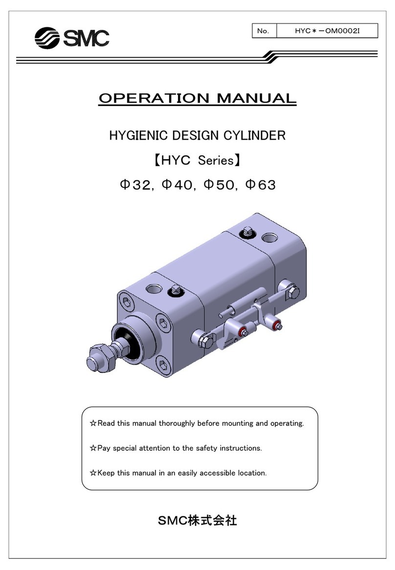
  9. SMC Networks E-MY2B Series User manual

SMC Networks E-MY2B Series User manual

Series
E-MY2B
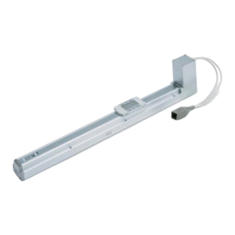
e-Rodless Actuator
Integrated control type
Remote control type
Suitable for light-load transfers.
Combined with various guide types.
Supported by guides
Workpiece applied directly
E-MY2B
Workpiece
E-MY2B
Workpiece
Guide
1089
LJ1
LG1
LTF
LC1
LC7
LC8
LXF
LXP
LXS
LC6첸
LZ첸
LC3F2
X첸
D-첸
E-MY
Speed / Acceleration Specifications
Switch
turned
NO.
Heavy load
6
(10)
11
(20)
Payload
16
25
Nominal
size
1
2
3
4
5
6
7
8
9
10
0.25
0.49
0.74
0.98
1.23
1.47
1.72
1.96
2.21
2.45
Standard load
4
(5)
8
(10)
0.49
0.74
0.98
1.23
1.47
1.96
2.45
2.94
3.92
4.90
Medium load
2.5
(2.5)
4
(5)
0.98
1.47
1.96
2.45
2.94
3.92
4.90
5.88
7.84
9.80
Light load
1.25
(1.25)
2.5
(2.5)
1.96
3.94
3.92
4.90
5.88
7.84
9.80
11.76
15.68
19.60
Load Spec. and Acceleration Variation
Acceleration
(kg)
Side Support
The cylinder tube can be fixed from upward or downward.
Controller
No Programming
Required
Realizes similar controllability by
simple commands as a pneumatic
cylinder. Stroke learning
Speed /
Acceleration settings
Automatic
operation
Operable by the same signals (PLC)
as the solenoid valve.
Automatic
operation
Operable by the same signals (PLC)
as the solenoid valve.
Floating Bracket
Easy connection to an external guide. Two mounting directions are available.
Stroke
Adjusting Unit
( ): Using a guide externally.
Switch
turned
NO.
Main adjustment range
Low speed
10 to 100
1
2
3
4
5
6
7
8
9
10
10
20
30
40
50
75
100
300
500
1000
Medium speed
50 to 300
50
75
100
125
150
200
250
300
500
1000
Standard speed
100 to 1000
(mm/s)
100
200
300
400
500
600
700
800
900
1000
Speed Variation
1090
Motor placement D
Motor placement T
Motor
Controller
Auto switch
PLC
Signal from an auto switch
Stop command
by external input
Remote ControlType
Easy to reset after installation as a result of the remote controller.
Suited for installing where it is difficult to reach because the controller can be operated in an easily accessible location.
쎲Cable length is selectable from 1 m, 3 m and 5 m.
쎲Improvement in the maximum operating temperature from 40°C to 50°C (Actuator unit only)
쎲Mounting method can be selected among 3 types.
Direct mount DIN rail mount L-bracket mount
M4 screw
(accessory) M5 tapped Mounting bracket Mounting bracket
5-point stoppable type
(2-point for both ends and 3-point for an intermediate stop)
5-point positioning is possible at any preferred locations.
3-point stoppable type
(2-point for both ends and 1-point for an intermediate stop)
One intermediate stop is possible beside stops at both ends.
Intermediate Stop
5-point
stoppable
type (with
streamer)
3-point
stoppable
type
Stop command by an external input such as a PLC or PC makes it possible to decelerate or stop a slider (as programmed).
Stop Functions by External Inputs (5-point stoppable type only)
Application example 1
∗Settings for emergency acceleration and speed cannot be changed.
Stop method
Quick start-up is possible after stopping.
100
±0.5 500
±1.0 1000
±2.0
Travelling speed (mm/s)
Repeatability (mm)
Repeatability of stop functions by external stop
Note) The valves shown are to be used as a selection guide and are
not guaranteed.
Application example 2
Signal from auto switches on the e-rodless
actuator can make it decelerate or stop.
Settings for speed/acceleration can be locked.
If the speed/acceleration switch is changed in the middle of lock-
ing, the alarm light will blink. However, the motion will continue in
accordance with the preprogrammed settings.
∗Settings for locking a stroke and intermidiate position are not
applicable.
Locking Functions
Indicator light for alarm
Speed/
Acceleration switch
Motor Placement: Mounting position of the
motor is user selectable and can either be
on the top or bottom of the actuator.
Stopping acceleration
(deceleration speed)
Initial motion speed
after stopping
Stop by external inputs
Value of a switch for
setting acceleration
Value of a switch for
speed
Emergency stop
4.9 m/s2
50 mm/s
Up
Down
1091
LJ1
LG1
LTF
LC1
LC7
LC8
LXF
LXP
LXS
LC6첸
LZ첸
LC3F2
X첸
D-첸
E-MY
Series
E-MY2B
Model Selection 1
Selection Flow Chart
Guideline for when the load spec is temporarily chosen.
Guideline for Tentative Model Selection
Model
E-MY2B
E-MY2C
E-MY2H
E-MY2HT
Guideline for tentative model selection
Stroke
accuracy
Use of
other guide
Direct loaded
(Horizontal)
Table
accuracy Direct mount
(Wall
mounting)
Load resistance
/ Moment
resistance
Note)
Payload (kg)
25
20
15
10
5
0
Heavy load
Standard load
Medium load
Light load
E-MY2B16 E-MY2B25
Direct mount of load
E-MY2B16 E-MY2B25
Combining with another guide Note)
E-MY2첸16 E-MY2첸25
→ See page 1113.With guide 쏔= C/H/HT
For e-rodless actuator series E-MY2C/H/HT,
refer to page 1113.
Note) Friction coefficient for combining with another guide is 0.1 or less.
Type
Basic type
Cam follower
guide type
Linear guide
single axis type
Linear guide
double axis type
Note
Light-load transfer; combining with another
guide; stroke accuracy is required.
Workpiece direct mounting; table and stroke
accuracy are required.
Workpiece direct mounting without restriction of mount-
ing direction; table and stroke accuracy are required.
Workpiece direct mounting without restriction of mount-
ing direction; table and stroke accuracy are required
especially when a heavy load or moment is applied.
Most suitable Suitable Usable Not recommended
Note) The table accuracy means the amount of table deflection when a moment is applied.
Tentative selection of model
Refer to the guideline when the
model is temporarily chosen.
Operating conditions
m: Load mass (kg)
L:Stroke (mm)
t:Target of tact time (sec)
Tentative selection of load specification
Refer to the guideline when the
load spec is temporarily chosen.
Tentative selection of operating speed
Refer to the guideline of tact time.
Model selected
Calculation of guide load factor
Refer to the guideline of calculation
of guide load factor.
OK
Select the
different guide type.
OK
Re-examine the operating conditions.
Change the model.
Change the model.
Change the
operating speed.
E-MY2B only NG
NG
1092
Guide Tact Time
Heavy load
specifications (2.45 m/s2)Standard load
specifications (4.90 m/s2)Medium load
specifications (9.80 m/s2)Light load
specifications (19.60 m/s2)
Note) Tact time may vary depending on the load mass or sliding resistance and thus value is not guaranteed.
Tact time (sec)
4.0
3.5
3.0
2.5
2.0
1.5
1.0
0.5
00 500 1000
Stroke (mm)
500
400
300 mm/s
600
1000
800
Tact time (sec)
4.0
3.5
3.0
2.5
2.0
1.5
1.0
0.5
00 500 1000
Stroke (mm)
500
400
600
800
1000
300 mm/s
Tact time (sec)
4.0
3.5
3.0
2.5
2.0
1.5
1.0
0.5
00 500 1000
Stroke (mm)
500
400
600
800
1000
300 mm/s
Tact time (sec)
4.0
3.5
3.0
2.5
2.0
1.5
1.0
0.5
00 500 1000
Stroke (mm)
500
400
600
800
1000
300 mm/s
Maximum Allowable Moment
Select the moment from within the range of
operating limits shown in the graphs. Note
that the maximum allowable load value
may sometimes be exceeded even within
the operating limits shown in the graphs.
Therefore, also check the allowable load
for the selected conditions.
Maximum Load Mass
Select the load mass from within the range
of limits shown in the graphs. Note that the
maximum allowable moment value may
sometimes be exceeded even within the
operating limits shown in the graphs.
Therefore, also check the allowable
moment for the selected conditions.
The graph value is for calculating the guide
load factors. Refer to the table below for
actual maximum load mass. The maximum
load mass shows the motor ability.
Refer to page 1099 for maximum load
mass value.
Caution
Select the required model by taking into
consideration the operating condition spec-
ifications and any possible specification
changes that may occur during operation.
Contact the nearest sales representative
for SMC's model selection software, which
will help in selecting the correct model.
Calculation of Guide Load Factor
1. Maximum allowable load (1), static moment (2), and dynamic moment (at the time of impact with
stopper) (3) must be examined for the selection calculations.
∗To evaluate, use υa (average speed) for (1) and (2), and υ(impact speed υ= 1.4 υa) for (3). Calculate m max
for (1) from the maximum load mass (m1, m2, m3) and Mmax for (2) and (3) from the maximum allowable moment
graph (M1, M2, M3).
Note 1) Moment caused by the load, etc., with actuator in resting condition.
Note 2) Moment caused by the impact load equivalent at the stroke end (at the time of collision to stopper).
Note
3)
Depending on the shape of the workpiece, multiple moments may occur. When this happens, the sum of the
load factors (Σα) is the total of all such moments.
1
3
2. Reference formulas [Dynamic moment at impact]
Use the following formulas to calculate dynamic moment when taking stopper impact into considera-
tion.
m: Load mass (kg)
F: Load (N)
FE: Load equivalent to impact (at impact with stopper) (N)
a: Set acceleration (m/s2)
υ: Impact speed (mm/s)
M: Static moment (Nm)
L1: Distance to the load’s center of gravity (m)
ME:Dynamic moment (Nm)
FE= m a
1
∴ME= — FEL1(Nm)
3
Note 4) Average load coefficient (= ):
This coefficient is for averaging the maximum load
moment at the time of stopper impact according to
service life calculations.
3. Refer to pages 1095 and 1096 for detailed model selection procedures.
FE
ME
υ
m
L1
Note 4)
Sum of guide
load factors Σα
=
Load mass [m] Static moment [M] Note 1) Dynamic moment [M
E
] Note 2)
Maximum load mass
[m max] Allowable static moment
[Mmax] Allowable dynamic moment
[M
E
max]
++ < 1
=
Model Selection
1093
LJ1
LG1
LTF
LC1
LC7
LC8
LXF
LXP
LXS
LC6첸
LZ첸
LC3F2
X첸
D-첸
E-MY
Types of Load Mass and Moment Applied to Rodless Actuators
Multiple moments may be generated depending on the mounting orientation, load, and position of the center of gravity.
Coordinates and moments
z
y
M3: Yawing
xM2: Rolling
M1:
Pitching
Horizontal mounting Wall mounting
Ceiling mounting
m3x g
x
M2z
M3
X
Z
y
m1x g
M1
X
x
M2
Yy
m2x g
M1
X
x
M2
Y
M1
FE
M3
Y
υa
Z
FE
M1E
υa
M3E
Load mass and static moment
Dynamic moment
mnx g
mnx g
E-MY2B/m1, m2, m3E-MY2B/M1, M3E-MY2B/M2
Load mass (kg)
100
10
1
100 1000
Speed (mm/s)
Moment (Nm)
Speed (mm/s)
10
1
0.1
100 1000
Moment (Nm)
Speed (mm/s)
10
1
0.1
100 1000
M1
M2
M3
m1x gx X
m1x gx Y
—
m2x gx X
m2x gx Y
—
—
m3x gx Z
m3x gx X
g: Gravitational acceleration (9.8 m/s2)
M1E
M2E
M3E
mnx a
Dynamic moment M2E does not occur.
Note) Regardless of the mounting orientation, dynamic moment is
calculated with the formulas above.
a: Set acceleration degree, υ: Set speed
Mounting
orientation
Static load (m)
Static
moment
Horizontal
mounting Ceiling
mounting Wall
mounting
m1m2m3
Mounting
orientation
Dynamic load (FE)
Dynamic
moment
Horizontal
mounting Ceiling
mounting Wall
mounting
x FEx Z
1
3
x FEx Y
1
3
Model Selection
1094
m1:Mass
m1 max (from 1 of graph m1) = 15.5 (kg) ...........................................................
Load factor 1= m1/ m1 max = 4 / 15.5 = 0.26
M1: Moment
M1 max (from 2 of graph M1) = 1.45 (Nm) .......................................................................................
M1= m1x g x X = 4 x 9.8 x 5 x 10–3 = 0.20 (Nm)
Load factor 2= M1/ M1 max = 0.20 / 1.45 = 0.14
2Load Blocking
3Calculation of Load Factor for Static Load
W: Workpiece (0.8 kg)
E-MY2B16-500
xy
z
xz
y
xy
z
Mounting Orientation
1. Horizontal
mounting 2. Wall
mounting
3. Ceiling
mounting
X
m1
m1
M1
20
10
Z
Y
Y
X
5W
Work-
piece no.
4 kg
Mass
(m)
5 mm
X-axis
10 mm
Y-axis
Center of gravity
Z-axis
20 mm
Mass and Center of Gravity for Workpiece
M2: Moment
M2 max (from 3 of graph M2) = 1.15 (Nm) .....................................................................................
M3= m1x g x Y = 4 x 9.8 x 10 x 10–3 = 0.39 (Nm)
Load factor 3= M2/ M2 max = 0.39 / 1.15 = 0.34
m1
M2
Y
Calculation of Guide Load Factor
Series
E-MY2B
The following are steps for selection with series E-MY2B best suited for your application.
Model Selection 2
Note) Regarding the speed and
acceleration setting, se-
lect from the speed/ac-
celeration chart on page
1099.
1Operating Conditions
Operating cylinder E-MY2B16-500
Set speed υ600 mm/s Note)
Set acceleration degree a 4.9 m/s2Note)
Mounting orientation Horizontal mounting
1095
LJ1
LG1
LTF
LC1
LC7
LC8
LXF
LXP
LXS
LC6첸
LZ첸
LC3F2
X첸
D-첸
E-MY
Load Mass Allowable Moment
4Calculation of Load Factor for Dynamic Moment
5Sum and Examination of Guide Load Factors
Σ= 1+2+3+4+5=0.26 +0.14 +0.34 +0.09 +0.05 =0.88 1
The above calculation is within the allowable value and therefore the selected model can be used.
In an actual calculation, when sum of guide load factors Σin the formula above is more than 1, consider decreasing
the speed or changing the product series.
Load FEat acceleration and deceleration
FE= m x a = 4 x 4.9 = 19.6 (N)
M1E: Moment
M1E max (From 4 of graph M1at 600 mm/s) = 1.45 (Nm) ..............................................
M1E =
—
x FEx Z =
—
x 19.6 x 20 x 10–3 = 0.13 (Nm)
Load factor 4= M1E / M1E max = 0.13 / 1.45 = 0.09
M3E: Moment
M3E max (From 5 of graph M3at 600 mm/s) = 1.45 (Nm) ....................................................
M3E =
—
x FEx Y =
—
x 19.6 x 10 x 10–3 = 0.07 (Nm)
Load factor 5= M3E / M3E max = 0.07 / 1.45 = 0.05
1
31
3
1
31
3
M1
M3
Y
FE
FE
Z
M1E
M3E
Calculation of Guide Load Factor
m1, m2, m3
Speed (mm/s)
Load mass (kg)
100
10
1100 1000
q
M3
Speed (mm/s)
Moment (Nm)
10
1
0.1100 1000
t
M2
Speed (mm/s)
Moment (Nm)
10
1
0.1100 1000
e
M1
Speed (mm/s)
Moment (Nm)
10
1
0.1100 1000
wr
<
=
Model Selection
1096
1097
LJ1
LG1
LTF
LC1
LC7
LC8
LXF
LXP
LXS
LC6첸
LZ첸
LC3F2
X첸
D-첸
E-MY
How to Order
Nominal size
16, 25
Standard stroke (mm)
100, 200, 300, 400, 500, 600, 700, 800, 900, 1000
∗Strokes are manufacturable in increments of 1 mm, up to 100 to 1000 strokes. (Strokes for less than 100 are not available.)
∗When exceeding a 1000 strokes, refer to “Made to Order” on page 1109.
Standard Stroke
∗Lead wire length symbols: 0.5 m Nil (Example) M9N
1 m M M9NWM
3 m L M9NWL
5 m Z M9NWZ
∗Solid state auto switches marked “ ” are produced upon receipt of order.
∗For details of auto switches with pre-wired connector, refer to pages 389 and 390.
∗Auto switch is shipped together with the cylinder (not assembled).
Applicable Auto Switches / For detailed auto switch specifications, refer to page 352 through to 402.
∗Arrow mark shows handling side on controller.
16
25
Nominal size
Stroke
N
PNPN
PNP
E-MY2B
16
Output type Nil
S
n
2 pcs.
1 pc.
n pcs.
Number of
auto switches
M
L
Z
1 m
3 m
5 m
Cable length
Nil
A3-point stoppable type
5-point stoppable type
Number of stoppable
positioning points
N100 T
M9BW
E-MY2B
16 N
M
100 T
M9BW
Refer to “Standard
Stroke” table.
Motor placement
On the top
On the bottom
T
D
Nil
Q—
CE marked
CE compliant
∗ No need to add a suffix
for the integrated control
type. It is provided with
a CE compliant product.
∗
Noise filter is provided
but not attached for the
“Q” spec.
W
W
Made to Order
(Refer to page 1099.)
Nil
M
E
W
None
Motor side only
End side only
Both sides
Stroke adjusting unit
L
M
Nil
Low
Medium
Standard
10 to 1000
50 to 1000
100 to 1000
Speed specifications∗[mm/s]
Motor
Controller
D
T
Auto switch
Nil Without auto switch
(built-in magnet )
∗ Refer to the table below for auto
switch model numbers.
∗The remote control
type can be selec-
ted by adding the
above symbols.
Load specifications∗
Load
specifications
Nominal
size
16
Symbol 25
∗( ): When combined with another guide and the fric-
tion coefficient is 0.1 or less.
∗∗ For details, refer to “Switch and Speed,” “Switch and
Acceleration” on page 1099.
Work load [kg]
Light load
Medium load
Standard load
Heavy load
1.25 (1.25)
2.5 (2.5)
4 (5)
6 (10)
2.5 (2.5)
4 (5)
8 (10)
11 (20)
D
E
Nil
Q
Type
Reed
switch Solid state
switch
Special
function
Indicator
light
Wiring
(Output) Load voltage
DC AC
Auto switch model
Electrical entry direction
Perpendicular
In-line
Lead wire length (m) ∗
0.5
(Nil) 3
(L) 5
(Z)
Applicable
load
Pre-wired
connector
IC circuit
IC circuit
IC circuit
—
—
IC circuit
—
Relay,
PLC
Relay,
PLC
—
—
—
—
—
—
1
(M)
—
—
—
A96
A93
A90
M9N
M9P
M9B
M9NW
M9PW
M9BW
A96V
A93V
A90V
M9NV
M9PV
M9BV
M9NWV
M9PWV
M9BWV
100 V
100 V or less
—
—
12 V
5 V
5 V
12 V
5 V, 12 V
12 V
5 V
12 V
12 V
24 V
—
24 V
3-wire (NPN equiv.)
2-wire
Yes
YesGrommet
None
Electrical
entry
3-wire (NPN)
3-wire (PNP)
2-wire
3-wire (NPN)
3-wire (PNP)
2-wire
Diagnostic
indication
2-color
display
—
Grommet
Remote
control type
Integrated
control type
∗ Standard type is not available for
high speed.
—
—
1098
e-Rodless Actuator
Basic Type / Nominal Size: 16, 25
Series E-MY2B
Basic Specifications
Option / Remote Controller
Mounting Bracket
L-bracket
DIN rail bracket
Description Part no.
MYE-LB
MYE-DB
Mass
Nomi-
nal
size
16
25 1.61
2.04 0.09
0.09
Basic
mass Additional
mass per
50 mm stroke 0.02
0.02
Stroke adjusting
unit mass (per unit)
How to calculate/Example: E-MY2B25-300WTNM
Actuator unit
Basic mass ................................. 2.04 kg
Additional mass .......................... 0.09/50 st
Actuator stroke ............................. 300 st
Unit mass ..................................... 0.02 g
2.04 + 0.09 x 300 50 + 0.02 x 2 = 2.62 kg
Remote controller unit
Controller body ............................. 0.24 kg
Cable length (3 m) ........................ 0.24 kg
0.24 + 0.24 = 0.48 kg
Unit: kg
Actuator Unit
Controller body
0.24 0.09
1 m 0.24
3 m 0.39
5 m
Cable length Unit: kg
Remote Controller Unit
∗ For an integrated control type, add 0.24 kg (controller
body) to the basic mass.
Made to Order
(For details, refer to page 1109.)
X168
Symbol Specifications
Helical insert thread specifications
Environmental Specifications
Integrated control type
Remote
control type
5 to 40°C
5 to 50°C
5 to 40°C
35 to 85%RH (No condensation)
–10 to 60°C (No condensation and freezing)
35 to 85%RH (No condensation)
Between all of external terminals and the case: 500 VAC for 1 minute
Between all of external terminals and the case: 50 MΩ(500 VDC)
1000 Vp-p Pulse width 1 µs, Rise time 1 ns
Standard
Available with -Q suffixed products only
Integrated control type
Remote control type
Electrical Specifications
Power supply voltage
Current consumption
Power supply voltage
Current consumption
24 VDC ±10%
Rated current 2.5 A (Max. 5 A: 2 s or less) at 24 VDC
24 VDC ±10%
30 mA at 24 VDC and Output load capacity
6 mA or less at 24 VDC/1 circuit (Photo coupler input)
30 VDC or less, 20 mA or less/1 circuit (Open drain output)
Emergency stop, Output deviation, Power supply deviation,
Driving deviation, Temperature deviation
Stroke deviation, Motor deviation, Controller deviation
Acceleration and deceleration method
Moving direction Both ends (Mechanical stoppers), 1 intermediate position
Both ends (Mechanical stoppers), 3 intermediate positions
±0.01 mm
±0.1 mm
10 N
20 N
Direct teaching, JOG teaching
Controller body
LED for power supply, LED for alarming, LED for positioning completion
Actuation command signal, Emergency stop input signal
Positioning completion signal, Emergency detection signal, Ready signal
E-MY2B
Model
Trapezoidal drive
Horizontal direction
10 to 1000 mm/s
50 to 1000 mm/s
100 to 1000 mm/s
Heavy load
0.25 to 2.45 m/s2
6 (10) kg
11 (20) kg
Standard load
0.49 to 4.90 m/s2
4 (5) kg
8 (10) kg
Medium load
0.98 to 9.80 m/s2
2.5 (2.5) kg
4 (5) kg
Light load
1.96 to 19.6 m/s2
1.25
(
1.25
)
kg
2.5 (2.5) kg
Speed / Acceleration
Switch no.
10
20
30
40
50
75
100
300
500
1000
50
75
100
125
150
200
250
300
500
1000
100
200
300
400
500
600
700
800
900
1000
1
2
3
4
5
6
7
8
9
10
Switch no. Heavy load
0.25
0.49
0.74
0.98
1.23
1.47
1.72
1.96
2.21
2.45
Standard load
0.49
0.74
0.98
1.23
1.47
1.96
2.45
2.94
3.92
4.90
Medium load
0.98
1.47
1.96
2.45
2.94
3.92
4.90
5.88
7.84
9.80
Light load
1.96
2.94
3.92
4.90
5.88
7.84
9.80
11.76
15.68
19.60
1
2
3
4
5
6
7
8
9
10
[mm/s]
Switch and Speed Note 1) Switch and Acceleration Note 2) [m/s2]
Low speed
Medium speed
Standard speed
Note 1) The factory default setting for the switch is No.1.
Note 2) The factory default setting for the switch is No.1.
Transfer speed set
range
Transfer speed acceleration set
range
Maximum load mass
Note 1), Note 2)
Low
Medium
Standard
Nominal size: 16
Nominal size: 25
Positioning spots
Repeated positioning
stopping precision
Intermediate stopping point positioning method
Positioning setting spot
Display
Input signal
Output signal
Allowable
external resistance
Note 3)
3-point stoppable type
5-point stoppable type
Nominal size: 16
Nominal size: 25
Both ends
Intermediate
stopping position
Note
1)
The maximum load mass shows the motor ability. Please consider it together with the guide load factor
when selecting a model.
Note 2) ( ): When combined with another guide and the friction coefficient is 0.1 or less.
Note 3) The resistance value of the attached equipment should be within the allowable external resistance value.
Made to
Order
Power supply
for driving
Power supply
for signals
Input signal capacity
Output load capacity
Emergency detection items
Operating
temperature
range
Operating humidity range
Storage temperature range
Storage humidity range
Withstand voltage
Insulation resistance
Noise resistance
CE marked
Actuator unit
Remote controller unit
1099
Series E-MY2B
e-Rodless Actuator
Basic Type
LJ1
LG1
LTF
LC1
LC7
LC8
LXF
LXP
LXS
LC6첸
LZ첸
LC3F2
X첸
D-첸
E-MY
Dimensions: Integrated Control Type
E-MY2B
Nominal size: 16
Nominal size: 25
Note) For the 3-point stoppable type, the I/O cable is a 9-core type and for the 5-point stoppable type, a 11-core type is used.
87.3
15.5
(51.8)
(102)
5
42 60
(96.7) 132.2
35.5 96.7
94
FG terminal M3 140 + Stroke
40
32.5
62
506
50
80
92
(34)60
4 x M5 x 0.8 depth 8 2 x 2 x ø9.5 counterbore
depth 5.4
ø5.5 through hole
Motor
Controller
40
62
32.5
(34) 92
5 50
506
140 + Stroke
50
80
60
4 x M5 x 0.8 depth 8 2 x 2 x ø9.5 counterbore
depth 5.4
ø5.5 through hole
Motor
Controller
A clearance of
40 mm or greater
is required.
10
87.3
15.5
(102)
42 60 5
(74.7) 101.7
27 74.7
72
FG terminal M3
32.5
20
160 + Stroke
80
60
(500)
Motor position D
Motor position T
I/O cable Note)
Power supply cable
(2 wires)
Slot for auto switch
2 x ø10
counterbore
depth 2
With floating bracket
(2 x M5 x 0.8 thread depth from bottom of counterbore 7.5)
(500)
32.5
20
160 + Stroke
80
60
Motor position D
Motor position T
I/O cable Note)
Slot for auto switch
Power supply cable
(2 wires)
With floating bracket
(2 x M5 x 0.8 thread depth from bottom of counterbore 7.5)
Nominal size Stroke
A clearance of
40 mm or greater
is required.
2 x ø10
counterbore
depth 2
1100
Series
E-MY2B
Dimensions: Remote Control Type (Actuator unit)
E-MY2B M
L
Z
Nominal size Stroke
Nominal size: 16
Nominal size: 25
∗ Refer to page 1102 for dimensions of remote controller.
Note) When the CE compliant model is selected, a noise filter is provided but not attached.
The cable for the CE compliant models uses the dedicated shielding. Even if a noise filter is attached to a non CE marked products, the products cannot be
changed to a CE compliant product.
(132.2)
(96.7) 35.5 96.7
94
60
40
32.5
62
506
505
140 + Stroke10
(34) 92
80
50
60
(60)
Motor
40
32.5
62
506
50
5
140 + Stroke10
(34) 92
80
50
60
(60)
ø5.5 through hole
Motor
(74.7)
60
(101.7)
72
74.727
32.5
2080
60
(210)
To remote controller
(210)
32.5
2080
60
Noise filter Note)
4 x M5 x 0.8
depth 8
2 x 2 x ø9.5 counterbore
depth 5.4
Encoder cable on actuator side
(4 wires) Noise filter Note)
Motor cable on actuator side
(6 wires)
160 + Stroke
Slot for auto switch
Motor position T
Motor position D
2 x ø10
counterbore
depth 2
With floating bracket
(2 x M5 x 0.8 thread depth from bottom of
counterbore 7.5)
4 x M5 x 0.8
depth 8
2 x 2 x ø9.5 counterbore
depth 5.4
ø5.5 through hole
To remote controller
Motor cable on actuator side
(6 wires)
Encoder cable on actuator side
(4 wires)
160 + Stroke
Slot for auto switch
Motor position T
Motor position D
2 x ø10
counterbore
depth 2
With floating bracket
(2 x M5 x 0.8 thread depth from bottom of
counterbore 7.5)
1101
Series E-MY2B
e-Rodless Actuator
Basic Type
LJ1
LG1
LTF
LC1
LC7
LC8
LXF
LXP
LXS
LC6첸
LZ첸
LC3F2
X첸
D-첸
E-MY
Dimensions: Remote Control Type (Remote controller unit)
L-bracket / MYE-LB (Option)
DIN rail bracket / MYE-DB (Option)
Note 1) For the 3-point stoppable type, the I/O cable is a 9-core type and for the 5-point stoppable type,
a 11-core type is used.
Note 2) When mounting the remote controller, use the included M4 screw or use the M5 tap located
on one side of the controller.
Note 3) When the CE compliant model is selected, a noise filter is included but not attached.
The cable for the CE compliant models uses the dedicated shielding. Even if a noise filter
is attached to a non CE marked product, the products cannot be changed to a CE compliant product.
Extention cable A dimension
M
L
Z
1000
3000
5000
(7.5)
42
21
11
87.3(11.8) 87.3
7
60
58
28 22.5
2
(67)
25
2 x ø5.5
60
4.3
(74.5)
73.6
35.5 22
5
15.5
6.5 87.1
5
60
42 44
FG terminal M3
Controller
I/O cable Note 1)
200 or less
(A) (500) 60
Noise filter Note 3)
2 x M5 depth 8
To actuator
Motor cable on controller side
(6 wires)
Encoder cable on controller side
(4 wires)
Power supply cable (2 wires)
Note 2)
2 x for M4 thread Note 2)
(accessory)
M5 x 8 2 pcs.
Hexagon socket head
cap screw (accessory)
M3 x 6.5 2 pcs.
Round head Phillips screw
(accessory)
M4 x 10 1 pc.
Round head combination
screw (accessory)
1102
Series
E-MY2B
Side support A
MY-S25A
Side support B
MY-S25B
Stroke Adjusting Unit
Side Support
50
35
8
91
77
M6 x 1
50
35 ø5.5
8
5
ø9.5
91
77
34.5
39
51
4 (Max. 8) 10
E-MY2B-A16A
Series E-MY2B
e-Rodless Actuator
Basic Type
1103
LJ1
LG1
LTF
LC1
LC7
LC8
LXF
LXP
LXS
LC6첸
LZ첸
LC3F2
X첸
D-첸
E-MY
Floating Bracket
Note) Mounting direction qand ware available for this model.
Application
Mounting Example
Application
Mounting Example
Mounting direction w(to minimize the installation width)
Workpiece
Bracket
Series E-MY2B
Guide
Floating mechanism
Mounting direction q(to minimize the installation height)
Workpiece
Floating mechanism
Bracket
Series E-MY2B
Guide
Installation of Holding Bolts
Slider
(Piston yoke) Pin
92
80
40
55
40 Za2
6
12
Zb2
ø9.5
12
6.5 (Screw length)
5.5 (Counerbore
depth) 41.5
M6 x 1 Zb1
112
90
11
22 45
55
24 Za1
1 1
1 1 1 1
Detail drawing of Zb1
(adjustable range)
Detail drawing of Za1
(adjustable range)
MYAJ25
Model
MYAJ25 Tightening torque
Unit: Nm
3
Floating Parts Dimensions
+0.2
10 0
-0.05
10-0.15
Conical spring
washer Holding bolt
Tightening Torque
for Holding Bolts
ø9.5
22
5.5 (Counerbore depth)
14 (Screw length)
49
M6 x 1
11
Detail drawing of Zb2
(adjustable range)
Detail drawing of Za2
(adjustable range)
1104
Series
E-MY2B
Names and Functions of Individual Part
Description Contents/Functions
Slider
Motor
Power supply cable
I/O cable
Controller unit
FG terminal
Encoder cable on actuator side
Motor cable on actuator side
Encoder cable on controller side
Motor cable on controller side
Moving part within the actuator
Motor activating the actuator
Power supply cable for providing power to the actuator
I/O cable for transmitting a positioning completion signal and driving instructions
The unit to control and set the actuator, and indicate its status
The terminal to connect the FG cable
Encoder cable for connecting the actuator with the controller
Motor cable for connecting the actuator with the controller
Encoder cable for separating the controller
Motor cable for separating the controller
Description Contents/Functions
1
2to 4
5
6
7
8
Stroke learning switch
Switch to move the slider to intermediate position and set the intermediate position
Rotary switch to set moving speed to the motor side end
Rotary switch to set moving speed to the other end
Rotary switch to set moving acceleration to the motor side end
Rotary switch to set moving acceleration to the other end
Switch
Indicator Light and the Display for the Basic Functions
Symbol Description Power
supply ON
A
B
C
D
E
MIDDLE Indicator light (Green)
MOTOR Indicator light (Green)
END Indicator light (Green)
PWR Indicator light (Green)
ALM Indicator light (Red)
—
—
—
쎻
—
Controller detail
Integrated control type Remote control type
Encoder cable on
controller side
I/O cable
Encoder connector
Motor connector
Power supply cable
Motor cable on
controller side
Encoder cable on
actuator side
Motor cable on
actuator side
wtqu
i
y
e
r
CE
B
D
A
Motor side
—
쎻
—
쎻
—
End side
—
—
쎻
쎻
—
Intermediate 1
쎻
—
—
쎻
—
쎻
쎻
—
쎻
—
쎻
—
쎻
쎻
—
Actuation instruction When decelerated
and completely
stopped
—
쎻
쎻
쎻
—
When the
alarm is
activated.
쎻
쎻
∗2
쎻indicates on status, and
—
indicates off status.
∗1 Displays for the 5-point stoppable type only.
∗2 When the alarm is activated, see page 1107 for the ALM display.
Series E-MY2B
e-Rodless Actuator
Basic Type
Controller
Motor
Slider
FG terminal
I/O
cable
Power supply
cable
Intermediate 2
∗1Intermediate 3
∗1
1105
LJ1
LG1
LTF
LC1
LC7
LC8
LXF
LXP
LXS
LC6첸
LZ첸
LC3F2
X첸
D-첸
E-MY
This product can be used without connecting I/O cables, however please use caution
and install a power supply switch for the actuator. In case of an emergency, please
turn it off.
Internal Circuits and Wiring Examples
Symbol Color Signal name Contents
DC1 (+)
DC1 (–) Brown
Blue Vcc
GND Power supply cables for
driving the actuator
Power Supply Cable 2-core AWG20 (20 wires/0.16 mm2)
Actuator status Symbol
OUT1
쎻
쎻
쎻
OUT2
쎻
—
쎻
OUT3
—
쎻
쎻
Output signal
I/O Cable Signals
Command
Motor side actuation instruction
End side actuation instruction
Intermediate actuation instruction
Symbol
IN1
쎻
—
쎻
IN2
—
쎻
쎻
Input signal
Symbol Color Signal name Contents
DC2 (+)
DC2 (–)
OUT1
OUT2
OUT3
OUT4
IN1
IN2
IN3
Brown
Blue
Pink
Orange
Yellow
Green
Purple
Gray
White
Vcc
GND
READY output
Positioning completion output 1
Positioning completion output 2
Alarm output
Actuation instruction input 1
Actuation instruction input 2
Emergency stop
Power supply cables for
signal
Signal indicating the
controller is operationable
Signal indicating that
positioning is completed
Signal indicating an alarm has been generated
Instruction signal to actuator
I/O Cable 9-core AWG28 (7 wires/0.127 mm2)
3-point Stoppable Type
쎻indicates on status, and
—
indicates off status.
This product can be used without connecting I/O cables, however please use caution
and install a power supply switch for the actuator. In case of an emergency, please
turn it off.
Symbol Color Signal name Contents
Power supply cables for
driving the actuator
DC1 (+)
DC1 (–) Brown
Blue Vcc
GND
Power Supply Cable 2-core AWG20 (20 wires/0.16 mm2)
Actuator status
Completion of motor side
end positioning
Completion of end
positioning
Completion of intermediate
1 positioning
Completion of intermediate
2 positioning
Completion of intermediate
3 positioning
Completion of external
input stop
Symbol
OUT1
쎻
쎻
쎻
쎻
쎻
쎻
OUT2
쎻
—
—
쎻
—
쎻
OUT3
—
쎻
—
—
쎻
쎻
OUT4
—
—
쎻
쎻
쎻
—
Output signal
I/O Cable Signals
Command Symbol
IN1
쎻
—
—
쎻
—
쎻
IN2
—
쎻
—
—
쎻
쎻
IN3
—
—
쎻
쎻
쎻
—
Input signal
Symbol Color Signal name Contents
Power supply cables for
signal
Signal indicating an alarm has been generated
Instruction signal to actuator
Signal indicating that
positioning is completed
Signal providing emergency stop
instruction (The emergency stop is
activated when contact is opened)
Signal indicating the
controller is operationable
DC2 (+)
DC2 (–)
OUT1
OUT2
OUT3
OUT4
OUT5
IN1
IN2
IN3
IN4
Brown
Blue
Pink
Orange
Yellow
Red
Green
Purple
Gray
Black
White
I/O Cable 11-core AWG28 (7 wires/0.127 mm2)
5-point Stoppable Type
쎻indicates on status, and
—
indicates off status.
NPN input/output circuit
PNP input/output circuit
NPN input/output circuit
Signal providing emergency stop
instruction (The emergency stop is
activated when contact is opened)
Completion of motor side end positioning
Completion of end positioning
Completion of intermediate positioning
Vcc
GND
READY output
Positioning completion output 1
Positioning completion output 2
Positioning completion output 3
Alarm output
Actuation instruction input 1
Actuation instruction input 2
Actuation instruction input 3
Emergency stop
Motor side actuation
instruction
End side actuation
instruction
Intermediate actuation
instruction 1
Intermediate actuation
instruction 2
Intermediate actuation
instruction 3
External input stop
instruction
Main circuit
Orange OUT2
Yellow OUT3
Green OUT4
Purple IN1
Gray IN2
White IN3
Brown DC1 (+)
Blue DC2 (
-
)
Pink OUT1
Brown DC2 (+)
Blue DC1 (
-
)
+
-
+
-
Load
Load
Load
Load
Power supply
for driving
24 VDC
Power supply
for signals
24 VDC
I/O cable
Power
supply
cable
Power
supply
switch
Main circuit
Orange OUT2
Yellow OUT3
Green OUT4
Purple IN1
Gray IN2
White IN3
Brown DC1 (+)
Blue DC2 (
-
)
Pink OUT1
Brown DC2 (+)
Blue DC1 (
-
)
+
-
+
-
Load
Load
Load
Load
Power supply
for driving
24 VDC
Power supply
for signals
24 VDC
I/O cable
Power
supply
cable
Power
supply
switch
Main circuit
Orange OUT2
Yellow OUT3
Red OUT4
Purple IN1
Gray IN2
Black IN3
Brown DC1 (+)
White IN4
Pink OUT1
Brown DC2 (+)
Blue DC1 (
-
)
Green OUT5
Blue DC2 (
-
)
+
-
+
-
Power supply
for driving
Power supply
for signals
I/O cable
Power
supply
cable
Power
supply
switch
Load
Load
Load
Load
24 VDC
24 VDC
Load
+
-
+
-
Main circuit
I/O cable
Power supply
for driving
Power supply
for signals
Power
supply
cable
Power
supply
switch
Load
Load
Load
Load
Orange OUT2
Yellow OUT3
Red OUT4
Purple IN1
Gray IN2
Black IN3
24 VDC
24 VDC
Brown DC1 (+)
White IN4
Pink OUT1
Brown DC2 (+)
Blue DC1 (
-
)
Load
Green OUT5
Blue DC2 (
-
)
1106
Series
E-MY2B
Error Display and Problem Solving
When the error indicator is displayed, refer to the following instructions.
w
Alarm output
50 ms
or longer
Emergency
stop input
READY output
(Releasing)
Item Display Contents Solution
Emergency
stop
Abnormal
external
output
Power supply
abnormality
Either the emergency
stop input is opened,
or the power supply
for the signal is cut-
off.
Confirm the power sup-
ply signal is energized
and release the emer-
gency stop input.
(Refer to the circuit dia-
gram on page 1106.)
External output is
short-circuited.
∗There is no external
alarm output signal.
In case of common
power supply, turn off
the power supply and
check the wiring condi-
tion of load. Restart the
power supply.
(Refer to the circuit dia-
gram on page 1106.)
The power supply
voltage is excessive
or lower than the limit
for operation.
Check the power sup-
ply voltage and adjust it
if necessary, then press
the MIDDLE button.
In case of an indepen-
dent power supply, turn
off the power supply for
the signals and check
the wiring condition of
load. Restart the power
supply.
(Refer to the circuit dia-
gram on page 1106.)
Drive
abnormality Maximum output is
continued for a pro-
longed period of time.
Check the work weight
and confirm that no for-
eign materials are at-
tached to the actuator.
After confirming, press
the MIDDLE button.
Temperature
abnormality Internal temperature
of the controller is
high.
Lower the surrounding
temperature of the ac-
tuator in use, and then
press the MIDDLE but-
ton.
Note) The product is in the same condition as when the stroke learning process is
completed.
Return to the home position is not performed by the initial input
• If the error can not be corrected, turn off the power supply to stop operation, and
contact your SMC sales representative.
Item Display Contents Solution
Abnormal
stroke
The motor is revolving
at excessive speed or
stops before target is
achieved.
If any foreign materials
are observed, remove
them and then press
the MIDDLE button.
In case of using the remote
controller type, please con-
firm the connection of the
connector part between the
motor and the controller,
after turning off the power
supply.
Motor
abnormality
Controller
abnormality
The motor does not
revolve properly or
over current is detec-
ted.
The switch settings
for speed and accel-
eration have been
changed while in a
locked condition.
∗There is no external
alarm output signal.
Press the MIDDLE but-
ton.
In case of using the re-
mote controller type,
please confirm the con-
nector part between
the motor and the con-
troller after cutting off
the power supply.
The CPU is malfunc-
tioning or the mem-
ory content is abnor-
mal.
Turn off the power sup-
ply and restart it.
After turning off the power
supply, check to see
whether the stroke adjust-
ing unit is loose. If re-
quired, readjust the stroke
and perform the stroke
learning again. Note)
Reset the settings for
speed and acceleration
to the set values while
in a locked condition.
Error of the
set value
Light OFF Blinks Light ON
There are two types of alarm reset: alarm reset manually (a) and an alarm reset externally (b) by an external signal.
Alarm reset
a: Alarm reset manually
In the event of an alarm, simply pushing wwill revert from the alarm
state.
b: Alarm reset externally
In the event of an alarm, simply inputting an external emergency stop
signal for 50 ms or longer will return to the state prior to the alarm. The
emergency stop output will activate by releasing the input for the
emergency stop.
The followings are the reinstated condition.
• The slider will be free until the command for driving is applied.
• After being reverted, the next input command for driving makes it start.
The initial motion after being reverted is 50 mm/s of a traveling speed.
1107
Series E-MY2B
e-Rodless Actuator
Basic Type
LJ1
LG1
LTF
LC1
LC7
LC8
LXF
LXP
LXS
LC6첸
LZ첸
LC3F2
X첸
D-첸
E-MY
Auto Switch Proper Mounting Position (at Stroke End Detection)
Auto Switch Mounting
30
30 9
9
A
Operating range
Bore size
16
25
D-A9, D-A9첸V(mm)
34
34 4.5
4.5
A
Operating range
Bore size
16
25
D-M9첸, D-M9첸V
D-M9첸W, D-M9첸WV (mm)
When mounting an auto switch, first hold the switch spacer with your fingers and push it into the groove. Confirm that it is aligned evenly within the groove
and adjust the position if necessary. Then, insert the auto switch into the groove and slide it into the spacer.
After establishing the mounting position, use a watchmaker’s flat head screwdriver to tighten the switch mounting screw which is included.
Note) When tightening an auto switch mounting screw, use a watch-
maker’s screwdriver with a handle of approximately 5 to 6 mm in
diameter. Also, tighten with a torque of about 0.1 to 0.15 Nm.
As a guide, turn about 90°past the point at which tightening can
first be felt.
BMY3-016
16 25
Applicable bore size (mm)
Switch spacer model
Switch Spacer Model
Center of magnet
A
Note) Only adjust the setting position after confirming the auto switch is properly activated.
Note) The operating range is a guide including hysteresis, but
is not guaranteed. There may be large variations (as
much as ±30%) depending on the ambient environment.
Switch mounting screw (Included as accessory)
(M2.5 x 4 l)
Flat head watchmaker’s screwdriver (Not included as accessory)
Switch spacer
(BMY3-016)
1108
Series
E-MY2B
Auto Switch Specifications

Other manuals for E-MY2B Series

1

This manual suits for next models

3

Other SMC Networks Controllers manuals

SMC Networks CRJ Series User manual

SMC Networks

SMC Networks CRJ Series User manual

SMC Networks ASP Series User manual

SMC Networks

SMC Networks ASP Series User manual

SMC Networks CRB2BW40 Series User manual

SMC Networks

SMC Networks CRB2BW40 Series User manual

SMC Networks ITV0000 Series User manual

SMC Networks

SMC Networks ITV0000 Series User manual

SMC Networks CRB10 User manual

SMC Networks

SMC Networks CRB10 User manual

SMC Networks LECP1 Series User manual

SMC Networks

SMC Networks LECP1 Series User manual

SMC Networks ITV10*0-CC****-Q Series Manual

SMC Networks

SMC Networks ITV10*0-CC****-Q Series Manual

SMC Networks JXC5H User manual

SMC Networks

SMC Networks JXC5H User manual

SMC Networks THERMO-CON HEC001 Series Use and care manual

SMC Networks

SMC Networks THERMO-CON HEC001 Series Use and care manual

SMC Networks EQY Series User manual

SMC Networks

SMC Networks EQY Series User manual

SMC Networks JXCL1 Series User manual

SMC Networks

SMC Networks JXCL1 Series User manual

SMC Networks EtherNet/IP JXC91 Series Owner's manual

SMC Networks

SMC Networks EtherNet/IP JXC91 Series Owner's manual

SMC Networks JXC73 Series Owner's manual

SMC Networks

SMC Networks JXC73 Series Owner's manual

SMC Networks ASBL Series User manual

SMC Networks

SMC Networks ASBL Series User manual

SMC Networks 4011 Series User manual

SMC Networks

SMC Networks 4011 Series User manual

SMC Networks VXFC-06A User manual

SMC Networks

SMC Networks VXFC-06A User manual

SMC Networks JXCE1 Series User manual

SMC Networks

SMC Networks JXCE1 Series User manual

SMC Networks ITVX Series User manual

SMC Networks

SMC Networks ITVX Series User manual

SMC Networks ITV1000 series User manual

SMC Networks

SMC Networks ITV1000 series User manual

SMC Networks 56-SS0750 Series User manual

SMC Networks

SMC Networks 56-SS0750 Series User manual

SMC Networks JAS-L Series User manual

SMC Networks

SMC Networks JAS-L Series User manual

SMC Networks LECP6 Series User manual

SMC Networks

SMC Networks LECP6 Series User manual

SMC Networks CRQ2 Series User manual

SMC Networks

SMC Networks CRQ2 Series User manual

SMC Networks LECP6 Series Manual

SMC Networks

SMC Networks LECP6 Series Manual

Popular Controllers manuals by other brands

InnoMedia InnoMedia ESBC 9578-4B Quick install guide

InnoMedia

InnoMedia InnoMedia ESBC 9578-4B Quick install guide

SMART-AVI EZ-WALL 2X2L user manual

SMART-AVI

SMART-AVI EZ-WALL 2X2L user manual

Delta 29FWC-100E instruction manual

Delta

Delta 29FWC-100E instruction manual

WindowMaster WSC 304 6102 operating manual

WindowMaster

WindowMaster WSC 304 6102 operating manual

Proportion-Air ISQB1 Installation & maintenance instructions

Proportion-Air

Proportion-Air ISQB1 Installation & maintenance instructions

Zero88 ILLUSION 500 operating manual

Zero88

Zero88 ILLUSION 500 operating manual

Kieback&Peter BMR410 Product description

Kieback&Peter

Kieback&Peter BMR410 Product description

Timeguard SLB2300 Installation & operating instructions

Timeguard

Timeguard SLB2300 Installation & operating instructions

Promise FastTrak S150 TX2plus quick start guide

Promise

Promise FastTrak S150 TX2plus quick start guide

effeff 750 operating instructions

effeff

effeff 750 operating instructions

Show Tec Fademaster 16 manual

Show Tec

Show Tec Fademaster 16 manual

wattstopper DRD8 v2 installation instructions

wattstopper

wattstopper DRD8 v2 installation instructions

Meanwell ELG-200 Series user manual

Meanwell

Meanwell ELG-200 Series user manual

WindowMaster MotorController WCC 310 Installation instructions manual

WindowMaster

WindowMaster MotorController WCC 310 Installation instructions manual

red lion PXU manual

red lion

red lion PXU manual

Dynalite DBC410 installation manual

Dynalite

Dynalite DBC410 installation manual

Black Box servswitch DTX5000-CTL user guide

Black Box

Black Box servswitch DTX5000-CTL user guide

Welbilt Frymaster YUM WINGSTREET K3000 Operation manual

Welbilt

Welbilt Frymaster YUM WINGSTREET K3000 Operation manual

manuals.online logo
manuals.online logoBrands
  • About & Mission
  • Contact us
  • Privacy Policy
  • Terms and Conditions

Copyright 2025 Manuals.Online. All Rights Reserved.