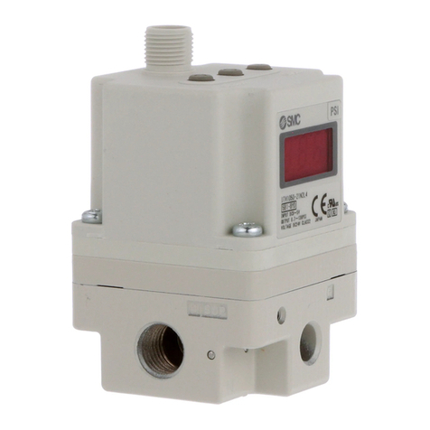
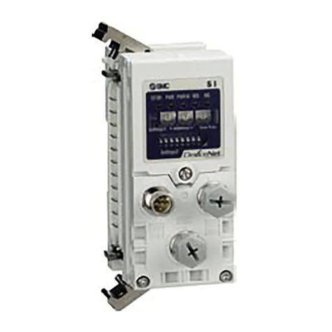
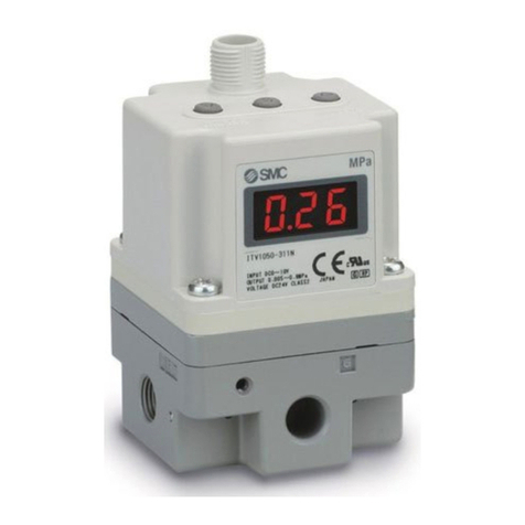
ITV2-PR-TFM132
Installation and Maintenance Manual
Electro-Pneumatic Regulator (for PROFIBUS DP)
ITV10*0-PR****-Q,
ITV20*0-PR****-Q,
ITV30*0-PR****-Q
1 Safety Instructions
This manual contains essential information for the protection of users and
others from possible injury and/or equipment damage.
• Read this manual before using the product, to ensure correct handling,
and read the manuals of related apparatus before use.
• Keep this manual in a safe place for future reference.
• These instructions indicate the level of potential hazard by label of
“Caution”, “Warning” or “Danger”, followed by important safety
information which must be carefully followed.
• To ensure safety of personnel and equipment the safety instructions in
this manual and the product catalogue must be observed, along with
other relevant safety practices.
Caution Indicates a hazard with a low level of risk, which if
not avoided, could result in minor or moderate
injury.
Warning Indicates a hazard with a medium level of risk,
which if not avoided, could result in death or
serious injury.
Danger Indicates a hazard with a high level of risk, which if
not avoided, will result in death or serious injury.
• Electromagnetic compatibility:
This product is class A equipment intended for use in an industrial
environment. There may be potential difficulties in ensuring
electromagnetic compatibility in other environments due to conducted as
well as radiated disturbances.
• The compatibility of pneumatic equipment is the responsibility of
the person who designs the pneumatic system or decides its
specifications.
Since the products specified here can be used in various operating
conditions, their compatibility with the specific pneumatic system must
be based on specifications or after analysis and/or tests to meet specific
requirements.
• Only trained personnel should operate pneumatically operated
machinery and equipment.
Compressed air can be dangerous if an operator is unfamiliar with it.
Assembly, handling or repair of pneumatic systems should be performed
by trained and experienced personnel.
• Do not service machinery/equipment or attempt to remove
components until safety is confirmed.
• Inspection and maintenance of machinery/equipment should only be
performed after confirmation of safe locked-out control positions.
• When equipment is to be removed, confirm the safety process as
mentioned above. Switch off air and electrical supplies and exhaust all
residual compressed air in the system.
• Before machinery/equipment is re-started, ensure all safety measures
to prevent sudden movement of cylinders etc. (Supply air into the
system gradually to create back pressure, i.e. incorporate a soft-start
valve).
• Do not use this product outside of the specifications. Contact SMC
if it is to be used in any of the following conditions:
• Conditions and environments beyond the given specifications, or if the
product is to be used outdoors.
• Installations in conjunction with atomic energy, railway, air navigation,
vehicles, medical equipment, food and beverage, recreation equipment,
emergency stop circuits, press applications, or safety equipment.
• An application, which has the possibility of having negative effects on
people, property, or animals, requiring special safety analysis.
• Ensure that the air supply system is filtered to 5 microns.
2 Specifications
Model ITV*010 ITV*030 ITV*050 ITV2090
Min.supply pressure (Set pressure) + 0.1 MPa (Set pressure)
–13.3 kPa
Max.supply pressure 0.2 MPa 1.0 MPa 1.0 MPa -101 kPa
Set pressure range 0.005 ~
0.1 MPa 0.005 ~
0.5 MPa 0.005 ~
0.9 MPa -1.3 ~ -80 kPa
Supply voltage 24 VDC±10%
Current consumption Max. 160 mA
Input/output data 12bit/12bit (data 4095 corresponds to 100%F.S.)
Linearity Max. ±1%F.S.
Hysteresis Max. 0.5%F.S.
Repeatability Max. ±0.5%F.S.
Sensitivity Max. 0.2%F.S.
Temperature characteristics Max. ±0.12%F.S./°C
Operating temperature 0~50°C (without condensation)
Protection structure IP65
Model ITV10*0 ITV20*0 ITV30*0
Size (mm) 50×50×124 50×50×146 66×66×167
Weight (No option) 350 g 450 g 750 g
Table 1.
3 Operation Principle
When the input signal increases the supply solenoid valve nturns on and
the exhaust solenoid valve oturns off. Supply pressure is passed to the
pilot valve pthrough the supply solenoid valve. The pilot valve will open
the main valve allowing partial supply pressure to pass to the out port. The
pressure sensor qwill provide output pressure feedback to the control
circuit r. The control circuit will balance the input signal and output
pressure to ensure that the output pressure remains proportional to the
input signal.
Fig. 1 - Control diagram
Fig. 2 - Schematic diagram
4 Wiring
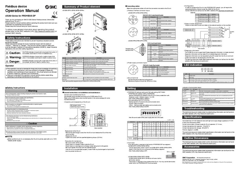
Connect the cable to the connector on the main unit as shown in the
following diagram. Take precautions, as incorrect wiring will damage the
unit. Use a DC power supply capable of supplying the necessary power
requirements with minimal ripple. When 3 m straight cable connection is
specified, this refers to the power supply cable, the communications cable
should be ordered separately.
Item Pin assignment Wire colour (Note)
1. +24 V Brown
2. N.C. –
3. GND Blue
Connector for
power supply 4. N.C. –
1. N.C. –
2. RXD/TXD_N(A) Green
3. N.C. –
4. RXD/TXD_P(B) Red
Connector for
communication
5. N.C. –
Table 2.
Note: Wire colour when the optional cable is used.
5 LED Display and Communication Protocol
• LED Display
Fig. 3 – Features of the ITV.
ITEM LED ON LED OFF
RUN Power ON (Green) Power OFF
DIA Diagnostic error (Red) Internal operation is normal
BF Profibus communication error (Red) Profibus communication is normal
Table 3.
• Communication Protocol
Item Specification Remark
Communication
protocol PROFIBUS DP For DP-V0
Baud rate (Note) 9.6 k/ 19.2 k/ 45.45 k/
93.75 k/ 187.5 k/ 500 k/ 1.5 M/
3 M/ 6 M/ 12 Mbps
Set by master
GSD-File SMC_1412.GSD
Occupied area
(Input/output data) 1 word / 1 word Lower 2 bits of 7 bytes of
diagnostic area are for diagnostic
information.
Communication
data resolution 12 bit (4096 resolution)
Address setting Switch setting /
Software setting Switching by switch
Terminator Built into the product Switching by switch
Table 4.
Note: Baud rate relates to communication distance
6 Switch Setting
• Selection of address setting mode
Node address of the product can be set by
software mode (SW) or hardware mode (HW).
When software mode is selected, the
communication master sets the node address.
Setting range is 1 to 125.
• Address set switch
In hardware mode use the switches
shown, to set the node address.
• Address setting range is 01 to 99.
x10 x1
6 Switch Setting (continued)
• Setting the terminator
Set Profibus communication line terminator.
With terminator Without Without
(factory setting) terminator terminator
When the product is connected to the Profibus communication line,
ensure the switch is set to “with terminator”.
• Setting the address switch requires the removal of 4 screws in the front
panel of the unit (Fig 3). Take care as the panel hinges to a maximum of
90 degrees.
• After setting an address, always close and fix the panel securely.
Tighten the screws to torque of 0.6 – 0.8 N•m
7 Communication Data Allocation
Set target value
Resolution: 12 bit (100 %F.S.), Occupied byte: 2 Byte
000*
Target value (lower 12 bits)
Target value
(O area) b15 b11 b0
Put 0 in upper 4 bits (Note)
Monitor the output pressure
Resolution: 12 bit (100 %F.S.), Occupied byte: 2 Byte
000*
Output pressure (lower 12 bits)
Output pressure
(I area) b15 b11 b0
Resolution may exceed 12bit depending on control conditions.
Monitors the product error.
7 bytes are occupied for external diagnostic data.
Diagnostic data allocated to byte 7, as shown below.
Byte7 000000BA
Diagnostic (DIA) b7 b0
A. Internal diagnostic error 0: Normal 1: Error
B. Over range error 0: Normal 1: Error
Note: Although 100 %F.S. for target value is 12 bit, communication is
available upto 150 %F.S. (accuracy is guaranteed upto 100 %F.S.)
Over range error is output when 150 %F.S. is exceeded.
Output pressure at this time is controlled by the input data immediately
before the error occurred.
Pressure can be set by sending the input data, in which F.S. consists of
12 bits, to the E/P regulator through the master PLC (target value to
word area).
Setting data 0000h 0FFFh [(a/F.S.) x 4095]HEX
Output pressure 0 % x F.S. (=0) 100 % x F.S. a
fPressure sensor
gControl circuit
cSupply solenoid valve
dExhaust solenoid valve
Supply pressure
OUT
+
–
Input
signal ePilot valve
3
24
5
1
Power supply line
Communication line
BF LED
RUN LED
