Smipack T450 User manual

61 / 284
Use and maintenance manual
T450 - T650E - T650EF - T650 - T650F
ENGLISH
USE AND MAINTENANCE MANUAL
Heat-shrinking tunnel
T450 - T650E- T650EF
T650-T650F
MANUAL CODE:
CREATION DATE:
RELEASE:
RELEASE DATE:
DM210060
31.07.2000
6.0
07.02.2006
+
+
+
+
+
+
+
+
+
+
+
+
+
62 / 284
FOREWORD
In thanking you for the preference given us, SMIPACK S.p.A. is glad to welcome you
to its wide circle of Clients and wishes that the use of this machine will be for you
reason for full satisfaction.
This manual can be used for models T450-T650E-T650EF-T650-T650F and was
prepared with the aim to allow you to operate on the various components, explain the
various operations for maintenance and operation.
Where not expressly indicated by the ,instructions refer to all the above
mentioned models.
In order to guarantee a satisfactory level of efficiency, life and performance of the
machine, we urge you to scrupulously observe the instructions contained in this
manual.
SMIPACK S.p.A. is absolutely not responsible for any direct or non direct consequence
due to proper or non proper use of this publication or of the system software and has
got right to make technical modification on his system and on his manual without
advising the users.
SMIPACK S.p.A. - Viale Vittorio Veneto, 4 - 24016 San Pellegrino T. (BG) - Italy - Tel.
+39.0345.40400 - Fax +39.0345.40409.
PLEASE READ CAREFULLY AND FULLY THIS MANUAL BEFORE
INSTALLING THE MACHINE.
THIS MANUAL IS AN INTEGRAL PART OF THE PRODUCT AND MUST
ALWAYS ACCOMPANY THE SAME UP TO ITS DISMANTLING.

63 / 284
Use and maintenance manual
T450 - T650E - T650EF - T650 - T650F
ENGLISH
1. REGULATIONS AND GENERAL INSTRUCTIONS .......................... 65
1.1. HOW TO CONSULT AND USE THIS MANUAL ................................................................. 65
1.2. WARRANTY CONDITIONS ............................................................................................... 65
1.3. LEGAL REFERENCES ...................................................................................................... 66
1.4. REMARKS ON GENERAL SAFETY .................................................................................. 66
1.5. LEGEND ............................................................................................................................. 67
2. TUNNEL INSTALLATION .................................................................. 69
2.1. DESCRIPTION OF THE MACHINE ............................................................................... 69
2.2. CONTROL SYSTEMS ....................................................................................................... 69
2.3. WEIGHT AND DIMENSIONS OF THE PACKED TUNNEL ................................................ 70
2.4. WEIGHT AND DIMENSIONS OF THE TUNNEL ............................................................ 70
2.5. TRANSPORT AND UNPACKING ...................................................................................... 70
2.6. ASSEMBLY OF THE MACHINEFP560/A AND FP870A WITH THE TUNNEL .................. 71
2.7. POSITIONING TUNNEL ROLLER T450 ............................................................................ 72
2.8. POSITIONING THE TUNNEL ROLLER CONVEYOR BELT .............................................. 72
2.9. DEMOLITION AND DISPOSAL .......................................................................................... 72
2.10. ELECTRIC CONNECTION ................................................................................................. 72
2.11. TECHNICAL DATA FOR THE ELECTRIC CONNECTION ................................................ 73
2.12. CONDITIONS OF USE ....................................................................................................... 73
3. INFORMATION ON THE TUNNEL .................................................... 75
3.1. TUNNEL IDENTIFICATION ................................................................................................ 75
3.2. SHRINKING ........................................................................................................................ 75
3.3. DEFLECTOR REGULATION ............................................................................................. 76
3.4. TURNING ROLLERS ADJUSTMENT T450 ...................................................................... 76
3.5. OPERATING THE MACHINE WITH THE OVEN IN HEAT SHRINKING MODE ............... 77
3.6. TUNNEL LIMITATIONS AND SPECIFICATIONS OF USE ................................................ 78
4. PREPARATION TO THE USE OF THE TUNNEL ............................. 79
4.1. MACHINE START UP ........................................................................................................ 79
4.2. TURN ON / TURN OFF MENU [F1] ................................................................................... 79
4.3. OPERATING MODE MENU [F2] ........................................................................................ 80
4.4. QUICK SELECTION OF THE PROGRAMS ....................................................................... 80
4.5. USER MENU [F3] ............................................................................................................... 80
4.6. PARAMETERS MENU [F3 AND +] .................................................................................... 81
4.7. LEGEND OF THE SYMBOLS AND DISPLAY MESSAGES .............................................. 82
5. ROUTINE MAINTENANCE ................................................................ 83
5.1. NATURE AND FREQUENCY OF MAINTENANCE CHECKS AND OPERATION ...... 83
SUMMARY

64 / 284
Summary
5.2. LUBRIFICATION ................................................................................................................84
5.3. LIST OF SPARE PARTS ....................................................................................................84
TAV. 1. TRANSFORMER GROUP T450 - T650E .............................................................................................. 84
TAV. 2. TRANSFORMER GROUP T450 220V 3PH - T650EF - T650 - T650F ................................................. 85
TAV. 3. TRANSFORMER GROUP T650EF 220V 3PHF ................................................................................... 86
TAV. 4. ...................................................................................................................................................... 87
TAV. 5. ............................................................................................................................................................... 88
TAV. 6. ................................................................................................................................................................ 89
TAV. 7. T450 WITH TURNING ROLLER ..................................................................................................... 90
TAV. 8. T450 WITH TURNING ROLLER ....................................................................................................... 91
TAV. 9. T450 .................................................................................................................................................. 92
TAV. 10. T450 .................................................................................................................................................... 93
TAV. 11. T650E WITH TURNING ROLLER ................................................................................................... 94
TAV. 12. T650E WITH TURNING ROLLER ................................................................................................... 95
TAV. 13. T650EF ............................................................................................................................................ 96
TAV. 14. T650EF .............................................................................................................................................. 97
TAV. 15. T650 ................................................................................................................................................. 98
TAV. 16. T650 .................................................................................................................................................. 99
TAV. 17. T650 WITH TURNING ROLLER .................................................................................................... 100
TAV. 18. T650 WITH TURNING ROLLER .................................................................................................... 101
TAV. 19. T650F ............................................................................................................................................ 102
TAV. 20. T650F ............................................................................................................................................. 103
TAV. 21. ............................................................................................................................................................ 104
TAV. 22. ............................................................................................................................................................ 105
5.4. WIRING DIAGRAM T450 ............................................................................................106
5.5. WIRING DIAGRAM T450 (220V) ..............................................................................107
5.6. WIRING DIAGRAM T650E ......................................................................................108
5.7. WIRING DIAGRAM T650EF .....................................................................................109
5.8. WIRING DIAGRAM T650EF (220) ...................................................................................110
5.9. WIRING DIAGRAM T650 ....................................................................................111
5.10. WIRING DIAGRAM T650F ............................................................................................112
6. ANOMALIES AND FAILURES – HOW TO REMEDY ..................... 113
6.1. POSSIBLE CAUSES AND REMEDIES ............................................................................113
6.2. AUDIO WARNING OF PROBLEMS .................................................................................113

65 / 284
Use and maintenance manual
T450 - T650E - T650EF - T650 - T650F
ENGLISH
1.1 HOW TO CONSULT AND USE THIS MANUAL
Keeping of this manual
• This manual costitutes integral part of the machine and thus must be kept for as long
as the machine is in the user’s possession or, if that be the case, handed over to
any other user or subsequent owner.
• Use this manual in a way that will not damage all or part of its contents.
• Do not remove, tear or rewrite parts of this manual for any reason.
• Ensure that any amendment to this manual sent to you is incorporated in the manual
itself.
Consultation of the manual
The consultation of this manual is made easy be the insertion, in the first pages, of a
summary, which allows those consulting it to immediately locate the topic required and,
in the last pages, of an analytical index. The chapters are ordered following such a
structure to facilitate the research of the required information.
Method of updating the manual in case of modifications to the machine
The descriptions and drawings contained in the present manual are intended as non
refutative. SMIPACK S.p.A. reserves the right at any moment to apport modifications
to its machines (while keeping their essential characteristics), for the purpose of
improving their functionality and commercial and aestethic value, with no obligation to
update manuals and previous production except in exceptional cases.
Any updating or integration of the manual are to be considered as integral parts of the
manual. We would like to thank you in advance for all the suggestions that you may
want to forward to us in order to bring about further improvements to the machine.
SMIPACK S.p.A. - Viale Vittorio Veneto, 4 - 24016 San Pellegrino T. (BG) - Italy - Tel.
+39.0345.40400 - Fax +39.0345.40409
1.2 WARRANTY CONDITIONS
The machine is sent to the Client ready to be installed, and having passed, at our
factory, all expected tests and trials, in compliance with the current regulations. Within
the guarantee period SMIPACK S.p.A. undertakes to remove any eventual flaws and
defects, on the condition that the machine has been correctly used, and that the
indications found in its manuals have been respected. The warranty has a validity of
365 days from the date of purchase and covers all the materials and manufacturing
defects found by the builder. The warranty is valid only for the original buyer and
subject to the condition that the warranty certificate is duly filled in all its sections and
posted within 20 days from the date of purchase. The warranty is no longer valid if the
machine has been damaged through accident, misuse, breakdowns due to
atmospheric agents, maintenance operations or modifications carried out by
unauthorised personnel or not belonging to the servicing department of SMIPACK
S.p.A. Consumption materials, parts subject to normal wear and tear, transport from
the user to the servicing centre or vice-versa as well as labour are excluded from the
warranty and therefore are to be paid by the Buyer.
1. REGULATIONS AND GENERAL INSTRUCTIONS

66 / 284
1. Regulations and general instructions
1.3 LEGAL REFERENCES
The machine "heat-shrinking tunnel" complies to the Legislative Provisions of the law
that regulates the following Directives:
• MACHINE DIRECTIVE: 89/392/CEE, 91/368/CEE, 93/44/CEE, 93/68/CEE, 98/37/
CE.
• ELECTROMAGNETIC COMPATIBILITY DIRECTIVE: 89/336/CEE, 92/31/CEE,
and 93/97/CE.
• LOW TENSION DIRECTIVE: 73/23CEE
The directives have been followed considering the agreed norms, including:
• EUROPEAN SAFETY REGULATION FOR MACHINERY:
• EN 292/1 - EN 292/2 - EN 292/2/A1 - EN 294 - EN 349.
• ELECTRIC EQUIPMENT OF THE MACHINES: EN 60204-1.
• ASSEMBLED PROTECTION EQUIPMENT AND TRANSITION FOR LOW
TENSION (BOARD B.T.): EN 60439-1
1.4 REMARKS ON GENERAL SAFETY
The operator, before starting to work with this machine, must have acquired enough
knowledge on the location, function of the controls, characteristics of the machine, and
must have read this manual in all its entirety.
The employer must see to it that its personnel is informed on the following topics
relative to the safe usage of the machine:
• Accidents risks.
• Devices meant for the safety of the operator.
• General accidents prevention rules as provided by international directives and by
the laws of the country of destination of the machines.
It is necessary to comply to the following general precautions:
• Do not install the machine in areas posing a risk of explosion or fire.
• Do not temper with, remove or modify the safety devices; in such cases SMIPACK
S.p.A. declines any responsibility on the safety of its machines.
• Do not modify parts of the machine to install other devices without prior
authorization by SMIPACK S.p.A.; in case of unauthorized modifications the former
will not be held responsible for any possible consequences.
• Do not operate the machine in automatic mode with the fixed or mobile protections
removed.
• Do not open the fuse blocks with the mains on.
• Do not intervene on switches, valves and sensors without authorization.
• Do not intervene on the moving parts even without the aid of objects or tools.
• Do not manually oil or grease any moving part.
• Before carrying out any work on the electrical installation, ensure that the voltage
has been disconnected.
• After an adjustment or security operation, restore the state of the machine with
active protections.
ATTENTION!
The operator, the maintenance and cleaning personnel must scrupulously

67 / 284
Use and maintenance manual
T450 - T650E - T650EF - T650 - T650F
ENGLISH
adhere to both the regulations for the prevention of accidents and the safety
regulations of the Country of destination of the machine and the plant, besides
the instructions, warnings and general rules concerning the safety included in
this manual.
During maintenance or repair work on the machine, the latter has to be shut
down, and the special signals (MACHINE OFF FOR MAINTENANCE, DO NOT
START,etc...) have to be used. Make sure that the switches are not re-inserted
by unauthorized personnel.
1.5 LEGEND
All instructions and notes contained in this manual are graphically represented in the
following way:
ATTENTION: READ CAREFULLY BEFORE
OPERATING.
DANGER OF ELECTROCUTION: REMOVE
VOLTAGE BEFORE PERFORMING THE
INDICATED OPERATIONS.
DANGER OF ELECTROCUTION: EARTHING
IS COMPULSORY.
DANGER OF BURNING DUE TO HIGH
TEMPERATURE SURFACES.
WARNING! DON’T TOUCH.

68 / 284
1. Regulations and general instructions
DANGER OF TRAPPING BETWEEN
MECHANICAL MEMBERS.
DANGER OF SHEARING.
DO NOT CARRY OUT MAINTENANCE WITH
MEMBERS IN MOVEMENT.
WARNING! BEFORE OPERATING, CHECK
THAT THE MACHINE TYPE IS THE ONE THAT
HAS BEEN BOUGHT.

69 / 284
Use and maintenance manual
T450 - T650E - T650EF - T650 - T650F
ENGLISH
2.1 DESCRIPTION OF THE MACHINE
2.2 CONTROL SYSTEMS
2. TUNNEL INSTALLATION
Fig. 2.1.1
GLOSSARY
1OUTLET FAN ( T650EF - T650F)
2FANS MOTOR
3DEFLECTORS
4MAIN SWITCH
5CONVEYOR COOLING FANS
( T650EF - T650F)
2
3
4
5
1
Pos. Code Description Function
1EN200043
(T450 - T650E)
ELECTRONIC
CARD
IT ALLOWS THE CONFIGURATION
OF THE MACHINE ACCORDING
TO THE KIND OF TASK IT IS
SUPPOSED TO CARRY OUT
EN200044
(T650 - T650F
T650EF)
ELECTRONIC
CARD
EN200050
(T450 220V-T650EF
220V-T650E 220V)
ELECTRONIC
CARD
2EP010095 EMERGENCY
PUSH-BUTTON
IT STOPS THE MACHINE IN CASE
OF AN EMERGENCY
1
2
Fig. 2.2.1

70 / 284
2. Tunnel installation
2.3 WEIGHT AND DIMENSIONS OF THE PACKED TUNNEL
2.4 WEIGHT AND DIMENSIONS OF THE TUNNEL
2.5 TRANSPORT AND UNPACKING
Fig. 2.3.1
T450 T650E T650EF T650 T650F
X1420
mm
1415
mm
1845
mm
2280
mm
2280
mm
Y1030
mm
1220
mm
1220
mm
1220
mm
1220
mm
Z1555
mm
1725
mm
1725
mm
1725
mm
1725
mm
WEIGHT
Kg. 223 315 350 450 470
Y
Z
X
Fig. 2.4.1
T450 T650E T650EF T650 T650F
X1310
mm
1316
mm
1749
mm
1846
mm
2285
mm
Y933
mm
1147
mm
1147
mm
1147
mm
1162
mm
Z1439
mm
1615
mm
1570
1630
1615
mm
1570
1630
W500
mm
1010
mm
WEIGHT
Kg. 187 241 276 350 375
W
X
Y
Z
SMIPACK S.p.A. in function of the means of
transport and of the type of products to be
shipped utilizes packagings adequate to
guarantee the integrity and preservation
during transportation. It is recommended to
handle with great care the machine during
transport and positioning. The forwarder is
responsible for every damage that may
occur during transport. Unpack the unit
making sure not to damage any exposed
parts.

71 / 284
Use and maintenance manual
T450 - T650E - T650EF - T650 - T650F
ENGLISH
The lifting of the machine module must be carried out by means of hoisting systems
operating from below; due to the packaging modalities, it is not possible to use hoisting
systems operating from above.
Lift the machine from the longer side and adjust the forks of the forklift at the maximum
distance from each other.
ATTENTION!
Before handling make sure that the hoisting equipment are suitable to lift the
load that has to be handled.
In the case of long storing, place the machine in a sheltered environment with a
temperature between -15°C and +55°C degree of humidity, variable between 30% and
90% without condensation.
2.6 ASSEMBLY OF THE MACHINEFP560/A AND FP870A WITH THE
TUNNEL
After having unpacked the tunnel join the machine's conveyor belt to the tunnel's belt.
Insert the hooks of the machine's belt 1onto the roller 2placed in the tunnel entrance.
Fig. 2.6.1
2
1

72 / 284
2. Tunnel installation
2.9 DEMOLITION AND DISPOSAL
The tunnel does not contain dangerous components or substances that require
particular removal procedures. After the tunnel has been dismantled you must get rid
of the various materials according to the rules and regulations of the Country in which
the tunnel has to be disposed of.
2.10 ELECTRIC CONNECTION
ALL OPERATIONS FOR THE CONNECTION TO THE MAINS MUST BE CARRIED
OUT WITH NO VOLTAGE APPLIED TO THE TUNNEL.
2.7 POSITIONING TUNNEL ROLLER T450
Fig. 2.7.1
Insert the roller conveyor
belt into 1 the attachments of
the tunnel's conveyor belt
and lock it with the roller 2in
the special holes 3. In
assembly phase do not push
the roller conveyor belt
sideways because the
attachments could be
damaged 1.
Just make it slide as shown
by the arrow in the figure.
2.8 POSITIONING THE TUNNEL ROLLER CONVEYOR BELT T650
Fig. 2.8.1
Insert the roller conveyor
belt into the external side 1
of the tunnel's conveyor belt
and lock it with the supplied
screws 2. Make sure that the
roller conveyor belt is level
on the ground when the
tunnel's belt is tilted.
2
1
3
1
1
73 / 284
Use and maintenance manual
T450 - T650E - T650EF - T650 - T650F
ENGLISH
EARTHENING IS COMPULSORY!
The connection of the tunnel to the mains must be performed in compliance with the
regulation s in force in the country of the user.
Check that the tunnel frequency and supply voltage values (see data plate on the rear
side of the tunnel) correspond to the main's value.
ATTENTION!
IF THE ELECTRONIC CARD HAS TO BE EXTRACTED, REMEMBER TO REMOVE
THE VOLTAGE AND TO WAIT AT LEAST 5 MINUTES BEFORE OPERATING.
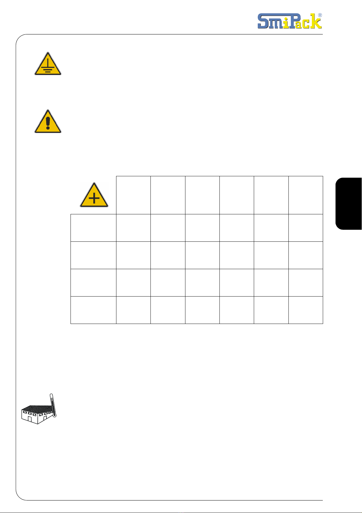
2.11 TECHNICAL DATA FOR THE ELECTRIC CONNECTION
2.12 CONDITIONS OF USE
THE MACHINE NEEDS AN INSTALLATION IN A CLOSED AND WELL AIRED
SURROUNDING,WHERE THERE ARE NOT ANY EXPLOSION OR FIRE
DANGEROUS. THE MINIMUM LIGHTING MUST BE 300 LUX.
Make sure that there is enough space for easy application and maintenance. Position
the machine in the planned space with no humidity, flammable materials, gas, and
explosives and making sure that it is level on the floor.
We suggest operating temperatures varying from +10°C to +40°C with a relative
humidity from 30% to 80% with no condensation.
The airborne noise is lower than 70 dB.
MACHINE PROTECTION DEGREE = IP32
Tab. 2.11.1
T450 T450
THREEPHASE T650 T650EF T650EF
THREEPHASE T650F
RATED
VOLTAGE 380-415 V ~ 220-240 V ~ 380-415 V ~ 380-415 V ~ 220-240 V ~ 380-415 V ~
RATED
FREQUENCY 50-60 Hz 50-60 Hz 50-60 Hz 50-60 Hz 50-60 Hz 50-60 Hz
RATED
POWER 7950 W 7950 W 15900 W 13850 W 13850 W 21300 W
RATED
CURRENT 11.5 A 21 A 23 A 23 A 40A 30.5 A
+40°C
+10°C

74 / 284
2. Tunnel installation
ATTENTION!
The pressure and the plate acoustical power of the machine can change
depending on the material of containers to be packaged. Therefore, the user
must perform an assessment on the noise exposure of his personnel in
accordance with the types of packages worked, so as to equip his operators with
suitable personal protection equipment.
75 / 284
Use and maintenance manual
T450 - T650E - T650EF - T650 - T650F
ENGLISH
The Tseries tunnel has been
designed to heat shrink the film.
The tunnel's conveyor belt is
connected to the machine's belt
FP end BP. For a good
packaging, film sealing must
take place at half the product
height. The raising (or the
lowering) of the belt implicates
the regulation of the tunnel's
curtain, this is necessary as it is
essential not to disperse heat
during the heat-shrinking
operation.
Adjust the height of the T650
tunnel and lock the belt with the
two screws 1.
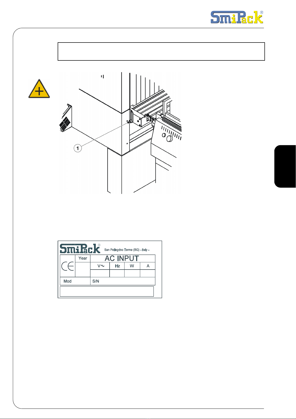
3.1 TUNNEL IDENTIFICATION
Fig. 3.1.1
On the rear of every tunnel
there is a data plate showing
the EC marking, the main
technical data such as model,
serial number, power, etc., that
will be notified to the builder in
case of problems.
3.2 SHRINKING
Film shrinking is obtained in the oven and is produced by the forced circulation of hot
air around the packaging. Air heating is obtained by making the same go through a
group of thermo-controlled resistors: a centrifugal fan moves the air. If the sealing
breaks during the shrinking it is possible to increase the speed of the belt or to lower
the temperature of the resistors by acting on the tunnel's control panel. Air heating is
obtained by making the same go through a group of thermo-controlled resistors: a
centrifugal fan moves the air. If the sealing breaks during the shrinking it is possible to
increase the speed of the belt or to lower the temperature of the resistors by acting on
the tunnel's control panel.
3. INFORMATION ON THE TUNNEL

76 / 284
3. Information on the tunnel
3.3 DEFLECTOR REGULATION
The T450, T650E, T650EF tunnels are equipped with a thermal chamber on which two
couples of deflectors are placed. The T650 and T650F tunnels are equipped with a
double thermal chamber and for each thermal chamber two couples of deflectors are
assembled. The top deflectors 1improve the heat shrinking of particularly high packs.
The low deflectors 2direct the air toward the low side of the product.
If the deflectors are opened, the air directed under the product decreases. Try to obtain
the best adjustment for the best heat shrinking.
Fig. 3.3.1
3.4 TURNING ROLLERS ADJUSTMENT T450
The product is normally conveyed by turning rollers, which grants a more
homogeneous film shrinking and a better packaging.
However, some films might tear if the rollers turn, because of the strict adherence of
the film to the rollers.
In order to find the best solution for each kind of film, the tunnel T450 can handle the
product both with turning rollers and with fixed rollers.
By means of lever A, situated on the outlet conveyour, it is possible to make the
following adjustments:
Fig. 3.4.1
1 • By keeping the lever in horizontal position, the rollers remain fixed.
2 • By turning the lever downwards, the rollers turn.
111
222
A

77 / 284
Use and maintenance manual
T450 - T650E - T650EF - T650 - T650F
ENGLISH
3.5 OPERATING THE MACHINE WITH THE OVEN IN HEAT
SHRINKING MODE
Fig. 3.5.1
Once the sealing on the packaging machine has concluded, the machine’s conveyor
belt transports the product onto the tunnel’s belt. The pack enters the tunnel for the
heat shrinking process. The electronic card positioned on the tunnel commands all the
variables of this process (internal temperature and belt speed). In the end, the heat-
shrunk product moves out of the tunnel and runs on the roller.
In case of emergency, stop the machine by pressing the STOP push-button. Then
open the curtains so that the tunnel cools down quicker. If necessary start the cooling
procedure (See Par. 5-2). Restore the tunnel’s normal operation as soon as possible.

78 / 284
3. Information on the tunnel
3.6 TUNNEL LIMITATIONS AND SPECIFICATIONS OF USE
DANGEROUS AREAS:
• Do not touch the inside of the oven during or immediately after a packaging. Danger
of burns due to the residual heat.
• Do not use the machine if the fans break.
• Do not touch the fan in movement or use the machine without curtains.

79 / 284
Use and maintenance manual
T450 - T650E - T650EF - T650 - T650F
ENGLISH
4.1 MACHINE START UP
Rotate the main switch to position 1. After the main video page, the tunnel's present
temperature is signalled on the first line while symbols indicate the state of operation
on the second line.
Fig. 4.1.1
The states of the machine that are displayed are:
• TUNNEL OFF: power is activated but the tunnel and belt are turned off.
• TUNNEL ON: tunnel and belt turned on.
• P.FREE: belt turned on and tunnel heating switched off.
• COOLING: tunnel off but belt and ventilation turned on to allow the tunnel to cool
down.
• FREE P/ COOLING: they flash alternatively to point out that the free passage mode
has been chosen but the tunnel cooling is in progress.
The first symbol on the left represents the operation mode:
• operation with tunnel heating ( “heat shrinking” mode); The symbol appears
between brackets when the oven is in “OFF.” A bar follows that indicates the
resistor's heating state. As soon as the 5 rectangles have disappeared it is possible
to carry out the heat shrinking. Each rectangle indicates a temperature lower than
20% compared to the set value.
• indicates that the tunnel fans are turned on. By deactivating the “heat
shrinking” mode the fans remain turned on until the temperature has dropped below
80 °C.
• The letter “M” indicates the selected memory.In the 6 available memory different
values can be saved according to the various products.
• To change video pages in the menu use the keys [×]or [Ø].
• To operate the change now use the keys [+] or [-].
4.2 TURN ON / TURN OFF MENU [F1]
To turn on the tunnel press the push-button [POWER] and then the push-button [F1].
The following video page will appear:
4. PREPARATION TO THE USE OF THE TUNNEL
TUNNEL ON °C:180
M1
Tunnel state
Switch on
tunnel resistor Heating
state
The tunnel
fans turn on
Memory
P
resent
temperature

80 / 284
4. Preparation to the use of the tunnel
Fig. 4.2.1
The tunnel can be turned off in the same way.
When the tunnel is hot always turn it off using the push-button [F1].
IIn this way the oven's cooling procedure is activated: fans and belt keep on turning
until the temperature drops below 80°C.
During this phase the following video page will be displayed:
Fig. 4.2.2
Turning off the tunnel according to a non-standard procedure (example pressing the
emergency push-button) is signalled by problem 9. To restore the normal operations
press the push-button [POWER] and then the push-button [F1].
4.3 OPERATING MODE MENU [F2]
This menu allows you to choose the operating mode.
By pressing the push-button [F2] the following video page will appear:
Fig. 4.3.1
By pressing the key [ENTER] the tunnel heating and the belt movement starts.
Pressing the key [ESC] will only start the belt movement.
4.4 QUICK SELECTION OF THE PROGRAMS
The microprocessor allows us to store up to 6 different programs, both in manual and
automatic cycle according to the size of the pack. The number of the program appears
at the end of the second line of the display. Press the push button [ENTER] and then
the keys [+] or [-] to modify the memory ( the power is disabled automatically). At this
point confirm the position of the memory with [ENTER] and enable the power again by
pressing the push button [POWER].
4.5 USER MENU [F3]
By pressing the push-button [F3] you can access to the following parameters:
1 • Belt speed
The following is the first video page displayed:
Tunnel
Esc=OFF Enter=ON
COOL.DOWN °C:180
M1
SHRINKING?
Esc=No Enter=Yes
This manual suits for next models
4
Table of contents
Other Smipack Packaging Equipment manuals


Popular Packaging Equipment manuals by other brands


AirSaver
AirSaver F2 Safety instructions, setup & installation manual

HUALIAN
HUALIAN M-PE Series Operation manual

Pro Pack Solutions
Pro Pack Solutions Eagle 710 Operation manual

Oliver
Oliver 1808-D User's operation

Kronos
Kronos H-46 Series Operation, safety and spare parts manual

Robopac
Robopac ROBOT S7 Use and maintenance manual