smirthwaite HARDROCK User manual

1 | Page
User Manual
Hardrock

2
CONTENTS
Contents
1.0 Safety Instructions and Warnings...........................................................................................4
1.1 Introduction .........................................................................................................................4
1.2 Service and Support ...........................................................................................................4
1.3 Symbols Used.....................................................................................................................5
1.4 Contraindications/Limitations ..............................................................................................5
1.5 Intended Use ......................................................................................................................6
1.5.1 Intended User...............................................................................................................6
1.6 Chair Operating Environment .............................................................................................6
1.6.1 Frequency of use:.........................................................................................................6
1.7 Vicinity to Other Equipment ................................................................................................7
1.8 Incident Reporting...............................................................................................................7
1.9 Additional Warnings and Safety Notices.............................................................................7
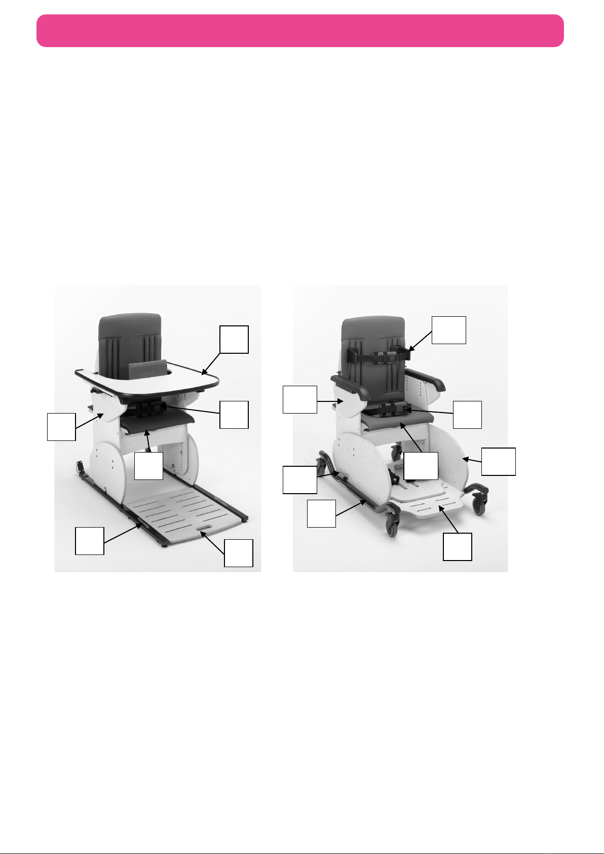
2.0 Components/Key Parts ..........................................................................................................9
2.1 Key Parts ............................................................................................................................9
2.2 Hardrock Configurations ...................................................................................................10
2.3 Packaging .........................................................................................................................10
3.0 Installation............................................................................................................................11
3.1 Adjustments ......................................................................................................................11
3.1.1 Seat Height ................................................................................................................11
3.1.2 Seat Depth .................................................................................................................11
3.1.3 Armrest.......................................................................................................................12
4.0 Compatible Accessories.......................................................................................................13
4.1 Tray...................................................................................................................................14
4.2 Thoracic Supports.............................................................................................................14
4.2.1 Height.........................................................................................................................14
4.2.2 Width ..........................................................................................................................14
4.3 Straps and Harnesses ......................................................................................................15
4.3.1 Pelvic Lap Strap .........................................................................................................15
4.3.2 4-Point Pelvic Strap....................................................................................................15
4.4 Buckle and Strap Operation..............................................................................................16
4.4.1 Buckle Strap (Standard) .............................................................................................16
4.4.2 Strap Length...............................................................................................................16
4.5 Heal Stop for Heal Huggy .................................................................................................16
4.6 Pommel.............................................................................................................................16
4.7 Stabilisers .........................................................................................................................17
4.7.1 Retrofitting.................................................................................................................. 17
4.7.2 Extend Stabiliser ........................................................................................................17

3
CONTENTS
5.0 Final Inspection ....................................................................................................................18
6.0 Technical Specification ........................................................................................................19
6.1 Chair Dimensions..............................................................................................................19
6.2 Environmental - Storage and Operating Conditions..........................................................19
6.2.1 Normal operating conditions.......................................................................................20
6.2.2 Shipping and storage conditions ................................................................................20
6.3 Standards Applied.............................................................................................................20
6.4 Disposal ............................................................................................................................20
7.0 General Inspection and Maintenance...................................................................................21
7.1 Daily Checks - To Be Completed by User.........................................................................21
7.2 Service Interval .................................................................................................................21
7.3 Nominal Service Life.........................................................................................................21
7.4 Extending Nominal Service Life ........................................................................................22
7.5 User Serviceable Parts .....................................................................................................22
7.6 Final Inspection.................................................................................................................22
8.0 Cleaning...............................................................................................................................23
8.1 General cleaning............................................................................................................... 23
9.0 Service Documentation ........................................................................................................23
9.1 Documentation/ Records ..................................................................................................23
9.2 Service Record History .....................................................................................................24
9.2.1 Product Information ....................................................................................................24
9.2.2 Service & inspection record form:...............................................................................24
10.0 Warranty ...........................................................................................................................25
11.0 Continuous improvement ..................................................................................................25

4
SAFETY INSTRUCTIONS AND WARNINGS
1.0 SAFETY INSTRUCTIONS AND WARNINGS
1.1 Introduction
The information in this manual is important to your safety.
Please read and understand this manual in its entirety before using your Hardrock
chair.
If you require larger print or videos – these are available on the Smirthwaite website:
www.smirthwaite.co.uk/product/Hardrock-chair/
The information in this manual is important for the safety of anyone near the Hardrock chair and
must be read and understood to help prevent injuries. It is also crucial to the proper operation and
maintenance of the Hardrock chair.
Store this manual with the documents included with the chair. The Hardrock chair is designed to
be used in conjunction with approved accessories. Please refer to any user guides supplied with
these components while reviewing this manual.
Contents of this manual are subject to change without prior notice.
Unauthorised modifications on any Smirthwaite product may affect its safety. The
manufacturer will not be held responsible for any accident, incident or deficiencies of
performance that occur as a result of any unauthorised modification to its products.
1.2 Service and Support
To ensure the safety and continued good function of your product, routine service must be
performed on your Hardrock chair.
As well as inspections and simple checks completed by the user, an annual service must be
completed by Smirthwaite Ltd. authorised trained service staff.
Contact your local authorised Smirthwaite dealer if you:
•Need more information.
•Have any questions about the use or maintenance of your Hardrock chair.
•Notice any change in the performance of your chair.
•Want to report an unexpected occurrence.
•Want to arrange a service.
Contact details of your local Smirthwaite dealer are shown on the last page of this manual.

5
SAFETY INSTRUCTIONS AND WARNINGS
1.3 Symbols Used
Consult instructions before
use
Caution
Class II Equipment -
electrical equipment in
which protection against
electric shock does not rely
on basic insulation only
Safe Working Load
represents the maximum
load rated for safe operation
Manufacturer
Date of manufacture
Packaging indicator – This
way up
Packaging indicator – Keep
dry
Serial number
For internal use only
Please observe local laws
on recycling
Degree of protection
provided by enclosure.
N1: Ingress of particles
N2: Ingress of water
Temperature range
Humidity range
Type ‘B’ applied part
Type ‘BF’ applied part
Medical Device
Authorised representative in
the European Community
1.4 Contraindications/Limitations
There are no known “contraindications” associated with the usage of the Hardrock chair and its
accessories, provided they are used as per manufacturer’s recommendations and guidelines.
Smirthwaite Ltd. does not recommend a required number of care givers for the use of our
products. This information and recommendation can only be provided after a thorough

6
SAFETY INSTRUCTIONS AND WARNINGS
personalized, case specific assessment, as there are many factors that can influence these
decisions.
1.5 Intended Use
For internal use only.
Intended to provide postural support.
1.5.1 Intended User
The Hardrock has been designed for use by a child’s carer,
therapist, and/or teaching staff who will maintain and clean the
chair as per the recommended guidelines in section 8.0 ‘Cleaning’. Under their care, they will be
responsible for helping the child in and out of the seat and their safety when sitting in the
Hardrock.
The Hardrock is designed to be checked and adjusted by a therapist to ensure the child is seated
correctly.
1.6 Chair Operating Environment
The Hardrock chair is suitable for use within the professional health care facility environment as
well as the home health care environment.
The chair is not intended to be used in environments where there are rapid changes in the
environmental temperature and humidity during intended use.
Based on research conducted during the concept stage, the following statements apply. See
Usability Technical File.
The Hardrock is intended for indoor use only; the normal operating conditions are as follows:
A. Temperature: 41°F to 86°F (+5°C to 40°C)
B. Relative Humidity: 15 to 90%, non-condensing, but not requiring a water vapour pressure
greater than 50hPa.
C. Atmospheric Pressure: 700hPa to 1060hPa.
D. Ambient luminance 50 – 500 lux.
E. Viewing distance: 0 metre to 1.5 metre
1.6.1 Frequency of use:
The Hardrock can be used without any frequency restrictions.

7
SAFETY INSTRUCTIONS AND WARNINGS
1.7 Vicinity to Other Equipment
Use of this equipment stacked with other equipment should be avoided, unless the equipment is
an approved accessory.
Contact your local authorised dealer if assistance is required – contact details on the last page of
this manual.
1.8 Incident Reporting
If, during the use of this device or as a result of its use a serious incident has occurred, please
report it to the manufacturer and the competent authority of the member state in which the user
and/or patient is established.
1.9 Additional Warnings and Safety Notices
•The user should NOT be left unattended whilst in the Hardrock. Always ensure a
responsible therapist or carer is in attendance.
•For the initial setting up of the Hardrock and at subsequent/future review of the child,
measurements of the child’s seat depth and height is required.
•The therapist should be familiar with the methods of adjustment and have completed all
adjustments appropriately to meet the needs of the child using the measurements taken
before transferring the child into the chair.
•Adjusting the seat height of the Hardrock is easier and safer if carried out by two people.
•Ensure all castors on the mobile base are locked with castors facing inwards by tilting the
chair slightly onto its side before making any adjustments.
•Rear transporter wheels have been fitted onto the skis to facilitate moving the chair. DO
NOT use whilst the child is seated in the chair.
Rear transporter wheels

8
SAFETY INSTRUCTIONS AND WARNINGS
•If rear transporter wheels have not been fitted, Hardrock should only be moved by two
people.
•Only Hardrock fitted onto mobile base can be used as an indoor transit chair.
•The Hardrock castors are designed for indoor use only and may be damaged if used
outdoors.
•The Hardrock is only to be used on a flat level surface.
•DO NOT EXCEED MAXIMUM WEIGHT LIMITS SPECIFIED
•Regular maintenance checks and cleaning are essential for the safe use of this equipment
(see care and maintenance section).
•If any part is loose, damaged or functioning incorrectly, do not use until rectified.
•Always fasten the pelvic strap and any other straps provided.
•Regularly check that they are not showing any signs of tearing or fraying and that they
fasten correctly.
•Ensure that all nuts, bolts and handwheels are securely tightened and that none are
missing.
•Always keep this product away from naked flames, cigarettes and sources of heat including
open fireplaces, radiators, heaters etc.
•DO NOT fit parts or accessories of other manufacturers to this product unless authorized to
do so in writing by Smirthwaite Ltd. Failure to follow these instructions will not only
invalidate the guarantee but could make the chair dangerous to use. Smirthwaite Ltd will
not accept liability for any injury or damage incurred through such malpractices. Any repairs
required must be carried out by Smirthwaite Ltd authorized personnel.

9
COMPONENTS/ KEY PARTS
2.0 COMPONENTS/KEY PARTS
2.1 Key Parts
When delivered, the chair will be supplied fully assembled except for the attachment of any special
accessories ordered. Export orders may require the chair to be fully assembled, which takes
approximately 2 minutes If in any doubt, always seek advice. Always turn hand wheels, levers and
screws clockwise to tighten or anti-clockwise to loosen. Conveniently packaged in a single box the
following components are included with your new Hardrock chair:
HARDROCK SIZE 1, 2 & 3
Code 8201-8203
HARDROCK SIZE 4
Code 8204
1.Ski
2.Pelvic strap
3.Footboard
4.Anti-thrust cushion
5.Armrest
6.Tray Note: Size 4 also comes with tray as
standard (not shown)
7.Mobile Base with lockable castors
8.Pelvic strap
9.Footboard
10.Anti-thrust cushion
11.Armrest
12.Extended gables (optional)
13.Stabilisers (optional)
14.Thoracic supports (optional)
Please see above to familiarise yourself with the components of the Hardrock chair. The image
above shows the key components of the Hardrock chair. If you have not received all the
components contact your local Smirthwaite dealer immediately – contact details are provided on
the last page of this manual.
2
3
6
5
4
9
10
11
13
12
14
1
7
8

10
COMPONENTS/ KEY PARTS
If your order has been supplied as a custom kit, please ensure you follow both the instructions
documented in this document and any additional instructions supplied. Please take note of any
instructions on the packaging/box when unpacking. Once the chair has been carefully unpacked,
please check all parts.
2.2 Hardrock Configurations
Smirthwaite Ltd. will document and maintain a record of the original product configuration at the
time of first sale. Smirthwaite Ltd. will not be held responsible for any subsequent changes to this
configuration unless authorized to do so in writing by Smirthwaite Ltd.
It is the equipment owner’s responsibility to maintain their own records of changes to the
equipment configuration and to be able to provide such records to subsequent owners to maintain
traceability.
We recommend an inspection/service by a Smirthwaite Ltd. Service Engineer (or Smirthwaite Ltd.
trained engineer) whenever a significant change is made to product configuration to ensure the
product is safe to use. If in any doubt, ALWAYS seek ADVICE.
2.3 Packaging
•When delivered, the chair will be supplied fully assembled except for the attachment of any
special accessories ordered.
•If your order has been supplied as a custom kit, please ensure you follow both the
instructions documented in this IFU and any additional instructions supplied.
•Please take note of any instructions on the packaging/box when unpacking.
•Once the chair has been carefully unpacked, please check all parts.

11
INSTALLATION
3.0 INSTALLATION
When delivered, the chair will be supplied fully assembled except for the attachment of any special
accessories ordered. Always turn hand wheels, levers and screws clockwise to tighten or anti-
clockwise to loosen.
3.1 Adjustments
3.1.1 Seat Height
•Lay the chair on its side. (2 people
required)
•Remove the 4 hexagon head screws
(A) on each side.
•With one person holding the top seat
section of the chair, slide the seat
section to the required height.
•Replace the 8 screws.
•Ensure all 8 screws match each
other equally in height holes.
•Tighten the screws.
•Return chair to upright position
3.1.2 Seat Depth
•Lift the front edge of the seat pad
attached with Velcro under the seat.
•Loosen the 4 hexagon screws (B) in the
slots on the edge of the seat by a just a
couple of turns.
•Slide the seat back or forwards to
desired depth.
•Tighten the screws.
A
B

12
INSTALLATION
3.1.3 Armrest
•Loosen the 2 hexagon screws ( C )
•Position at required height using any
of the holes available.
•Tighten the screws.
•Ensure that both armrests are set at
the same height and horizontal.
Always lock the castors when attaching items or making adjustments. To lock,
apply foot to point (A), to unlock apply foot to point (B).
C

13
COMPATIBLE ACCESSORIES
4.0 COMPATIBLE ACCESSORIES
The Hardrock chair comes with a variety of compatible accessories. These accessories and part
codes are listed below;
Accessories
Size 1
CODE
Size 2
CODE
Size 3
CODE
Size 4
CODE
Chair
8201
8202
8203
8204
Lower Leg Accessories
Mobile Base With Push Handle
MB010
MB010
MB012
MB012
Heel Huggy Plate
FP016
FP017
FP018
FP019
Stabilisers*
SB001
SB001
SB002
SB002
Extended Side Gables*
EG001
EG001
EG002
EG002
Seat Accessories
Pommel
PL020
PL020
PL021
PL021
4 Point Pelvic Strap*
HN073
HN074
HN075
HN076
Increased Height Backrest (Extra 100mm)*
BK154
BK155
BK156
BK157
Tray Accessories*
Tray Handrail Full Width
GB009
GB010
GB011
GB012
Padded Tray Insert (Fitted Top)
TR034
TR035
TR036
TR037
Padded Tray Insert (Fitted Underneath)
TR030
TR031
TR032
TR033
Front Tray Retaining Strap
ST053
ST053
ST053
ST053
Rear Tray Retaining Strap
ST054
ST054
ST054
ST054
Side Tray Retaining Strap
ST055
ST055
ST055
ST055
Back & Head Accessories
Moulded Pelvic Support
SP016
SP017
SP018
SP019
Trunk Supports With Straps
SP010
SP010
SP011
SP011
Samba Style Headrest Size 1
HT014
HT014
HT014
HT014
Samba Style Headrest Size 2
HT015
HT015
HT015
HT015
Cushions
25mm Pelvic Cushions (Pair)
CS138
CS139
CS140
CS141
38mm Pelvic Cushions (Pair)
CS142
CS143
CS144
CS145
50mm Pelvic Cushions (Pair)
CS146
CS147
CS148
CS149
62mm Pelvic Cushions (Pair)
CS150
CS151
CS152
CS153
75mm Pelvic Cushions (Pair)
CS154
CS155
CS156
CS157
25+25mm Pelvic Cushions (Pair)
CS210
CS211
CS212
CS213
38+25mm Pelvic Cushions (Pair)
CS221
CS222
CS223
CS224
50+25mm Pelvic Cushions (Pair)
CS214
CS215
CS216
CS217
62+25mm Pelvic Cushions (Pair)
CS218
CS219
CS220
CS221
* Items marked with * must be factory fitted at the time product is ordered
Sizes 2 & 3 come complete with adjustable armrests, anti-thrust cushion, tray, buckle pelvic strap
with pad and transporter base (consists of skis with transporter wheels and integrated footboard).
Size 4 comes complete with adjustable armrests, anti-thrust cushion, tray, buckle pelvic strap with
pad and mobile base with push handle.

14
COMPATIBLE ACCESSORIES
4.1 Tray
•Hold the sides of the tray
•Pull 2 plunger pins (D) out to
rest and park at an angle.
•Rest back of tray on armrest.
•Slide back of tray under the
tray retainer (E) and then to
desired position.
•Release pins securely into
position in the holes along the
armrest (F)
•Ensure chest pad is correctly
positioned in front of child for
safety, appropriate support
and reduce undesired
movement.
4.2 Thoracic Supports
4.2.1 Height
To adjust:
•Loosen handwheels on rear of seat.
•Move the thoracic support up or down to
desired position.
•Re-tighten the handwheels.
4.2.2 Width
To adjust:
•Loosen handwheels on rear of seat, and
remove from the vertical slots.
•Position the thoracic support
appropriate vertical slot for the desired
width.
•Re-tighten the handwheels.
F
E
D

15
COMPATIBLE ACCESSORIES
4.3 Straps and Harnesses
4.3.1 Pelvic Lap Strap
•The buckle is operated in the same way
as the thoracic supports (see section
4.2)
•To adjust the length on the strap, simply
adjust the amount of strap that is fed
through the cam-lock fasteners, which
are located on the back of the chair.
Towards the bottom of the backrest.
(G).
•To remove the strap completely, loosen
the cam-locks and retract the strap from
them.
4.3.2 4-Point Pelvic Strap
•The buckle and tri-glide adjustments are
operated in the same way as the
thoracic supports (see section 4.2)
•The upper straps are attached using the
same cam-lock fasteners at the pelvic
lap strap (see section 4.2)
•The lower straps are fed through the
base of the chair and are attached to
cam-lock fasteners on the underside
(H).
•To adjust the length on the strap, simply
adjust the amount of strap that is fed
through the cam-locks and tri-glides (if
applicable). See diagrams above and
below.
•To remove the strap completely, loosen
the cam-locks and retract the strap from
them.
G
H

16
COMPATIBLE ACCESSORIES
4.4 Buckle and Strap Operation
4.4.1 Buckle Strap (Standard)
•The buckle is secured by pushing (I)
into (J).
•To release the buckle, press both sides
of (I)
4.4.2 Strap Length
•The length of the straps can be altered
by adjusting the amount of the strap that
is fed through the cam-locks and tri-
glides (if applicable). See diagrams
across and below.
4.5 Heal Stop for Heal Huggy
•The heel stop can be adjusted in depth.
•Loosen the screws (K) by a couple of
turns.
•Slide it back or forwards to desired
depth.
•Re-tighten screws.
4.6 Pommel
Pommels have to be specified at the time of
order. A pommel cannot be retrofitted.
•
•To adjust:
•Loosen hand wheel
•Position the pommel in or out to the
desired position.
•
Re-tighten handwheels.
J
I
K

17
COMPATIBLE ACCESSORIES
4.7 Stabilisers
4.7.1 Retrofitting
•Slacken side panel fixing screws
located under the chassis
•Insert stabilizers through the ‘mouse-
hole’ (L) of the side panel.
•Turn the stabilizer to the vertical
position (as shown on the right).
•If needed, drill M8 clearance hole
through the baseboard
•Secure stabilizers with M8 cap screws,
nuts and washers.
•Re-tighten leg/side panel fixing screws
under the chassis
4.7.2 Extend Stabiliser
•Depress button (N)
•Pull stander tube out (M)
•Release button.
•Turn it vertical to the ground - there will
be an audible click when locked.
Always lock the castors when attaching items or making adjustments. To lock,
apply foot to point (A), to unlock apply foot to point (B).
L
N
M

18
FINAL INSPECTION
5.0 FINAL INSPECTION
When the service is complete:
•Remove any waste created as part of the service from the site.
•Confirm with the operator if the chair is safe to use and that it has been left in a working
state. Isolate the chair if it is not safe to operate.
•Complete all documentation – see Hardrock User Manual for more details
Incorrect use may result in personal injury or damage to objects.

19
TECHNICAL SPECIFICATION
6.0 TECHNICAL SPECIFICATION
6.1 Chair Dimensions
Code
Size
Seat height
(mm)
Width
(mm)
Seat
Depth
(mm)
Back
height
(mm)
Max user
weight (kg)
Product
weight (kg)
8201
1
220-315
290
230-305
300
50
35
8202
2
260-410
350
300-415
390
60
35
8203
3
290-440
430
370-485
370
70
40
8204
4
375-525
470
400-550
575
90
50
6.2 Environmental - Storage and Operating Conditions
The chair is intended for internal use within normal environmental conditions.
It is not intended to be used in environments where there are rapid changes in the environmental
temperature and humidity during intended use.
The Hardrock chair suffers little from any effects of lint, dust and light.
•Lint – Due to there being no mechanical or electrical mechanisms on the
Hardrock chair, lint would not affect the chair working.
•Dust – Due to there being no mechanical or electrical mechanisms on the
Hardrock chair, dust would not affect the chair working.
•Light –The Specification of the chair dictates that normal use would occur
during ambient luminance 50 – 500 lux. Additionally, as the chair is designed
for indoor use only, if required the user may wish to switch on room lighting.

20
TECHNICAL SPECIFICATION
6.2.1 Normal operating conditions
+5°C to +40°C (41°F to 104°F) at a relative humidity between 15% to 90% RH, non-condensing
but not requiring a water vapour pressure greater than 50hPa and atmospheric pressure between
700hPa to 1060hPa
6.2.2 Shipping and storage conditions
-25°C to +5°C (-13ºF to 41ºF) with any humidity level
+5°C to +35°C (41°F to 95°F) at a relative humidity up to 90%,
+35°C to 70°C non-condensing at a water vapour pressure up to 50hPa
During all transportation it is recommended that the chair remains in its original packaging.
It is recommended that the chair is stored in a cool, dry place out of direct sunlight. If cleaning is
required after storage, please see section 7.6 ‘Cleaning’ of the user manual for instructions.
Shipping and storage conditions are also contained on Hardrock Box Label:
6.3 Standards Applied
The standards that have been applied to the device are as follows:
•BS EN ISO 12182:2012 (Assistive products for persons with disability. General
requirements and test methods).
•IEC 62366:2015 (Application of usability engineering to medical devices).
•BS EN ISO 15233-1 :2016 (Medical devices — Symbols to be used with medical device).
6.4 Disposal
Please observe the local laws on recycling and respect the current laws for disposal within the
community the device is being used within. If there is any uncertainty of the below guidelines,
contact your local authorities to determine the proper method of disposal of potentially bio-
hazardous parts and accessories.
Other manuals for HARDROCK
1
Table of contents
Other smirthwaite Medical Equipment manuals

smirthwaite
smirthwaite SUNNI SEAT User manual

smirthwaite
smirthwaite 130 User manual

smirthwaite
smirthwaite Mobi Changer User manual

smirthwaite
smirthwaite 56861 User manual

smirthwaite
smirthwaite Mobi Shower Trolley User manual

smirthwaite
smirthwaite Samba User manual

smirthwaite
smirthwaite 8351 User manual

smirthwaite
smirthwaite Strato User manual

smirthwaite
smirthwaite BROOKFIELD+ User manual