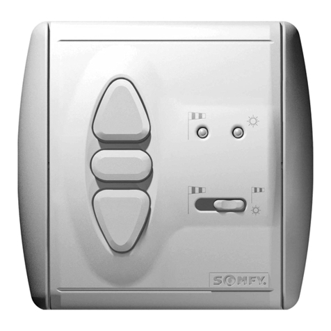
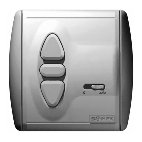
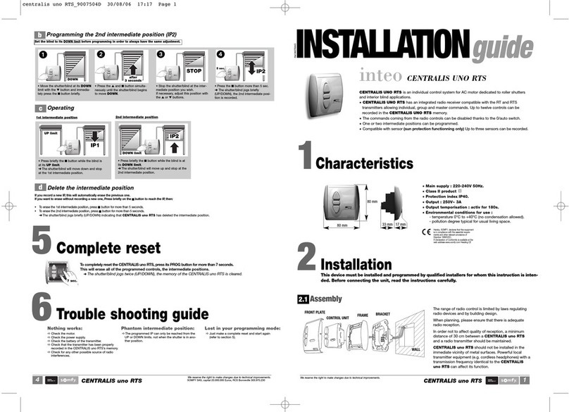
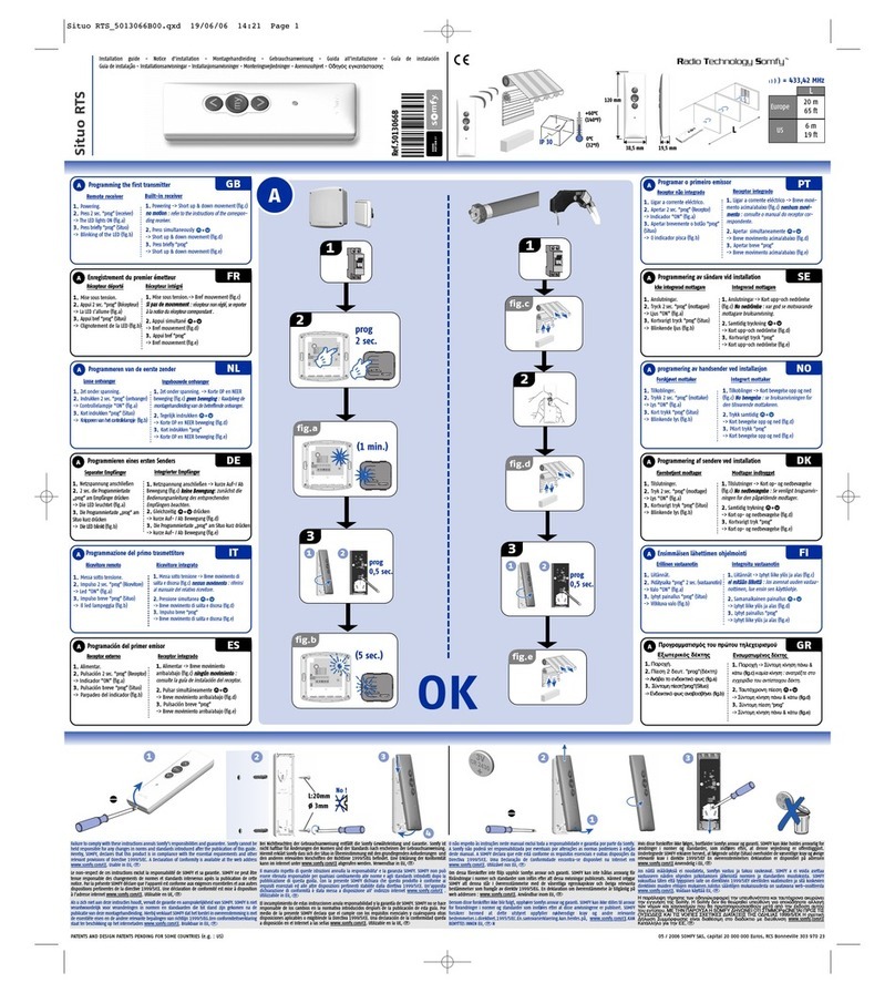
SOMFY Inteo SOLIRIS IB User manual

1
SOLIRIS IB
Supply:
Degree of protection:
Class:
Operating temperature:
Environmental conditions:
Relay contacts load:
33 mm 17 mm
EN60669
EN50081-1
EN50082-1
SOLIRISIBisawindandsunautomaticcontrolsystemforanInteoBUSline(IBBus).
Thewindspeedandamountofsunshinearemeasuredbyacombinedsensor.
Arainsensorcanalsobeconnected.
Whenthesunshines,theawning/blindisactivatedautomatically,either fully or to an indi-
viduallyprogrammedintermediateposition.
Adynamicretractiondelayavoidsfrequentactivationcommandscausedbyvarying light
conditions. Manualoperationisalsopossibleandthesunfunctioncanbeswitchedoff.
Ifthewindistoostrongtheawning/blindisautomaticallyretractedandmanualoperation
isblocked. Thewindfunctionisasafetyfunctionandisalwaysactivated.
220–240V~ 50/60Hz
IP40
II
+5°Cto+40°C
dry living areas.
500mA/50VDC
Settingup,testing,commissioningandtroubleshootingfor this equipment shouldonlybe car-
riedoutbyatrainedelectrician. Beforestartingwork,disconnectthe powerto all connecting
wires,andtakestepstopreventtheir accidental reconnection. Correctoperationisonly guar-
anteedwhenprofessionally installed and powersupplyisadequate.
!
80 mm
80 mm
INSTALLATION
guide
Ref.9007510
inteoSOLIRIS IB
1
Characteristics:
2
Installation:
We reserve the right to make changes due to technical improvements.

SOLIRIS IB
2
2 x
Connectthewiresto the termi-
nalsoftheconnecting bracket
inaccordancewiththe terminal
layout(chapter2.2).
Pressthesafetycover onto the
backofthebracket then fit this
oneontherecessed box.
Toremovethesafetycover,useascrew-
drivertopressgentlyintheslot provided in-
sidetheterminalblock.
PlugtheSOLIRISIB control
unitintothebracket,together
withthecoverframe.
Whensetting(chapter3) and
programming(chapter4)is
completed,the cover platecan
beclippedontothe control unit.
Terminal layout2.2
CL
N
Soliris IB connecting
Bracket
Terminal layout
Main Phase (L )
Main Neutral (N )
IB Bus common (C)
IB Bus Up ( )
IB Bus Down ( )
Common (C)
Sun sensor ( )
Wind sensor ( )
Rain sensor ( )
C
Mounting2.1
Soliris sensor
Rain sensor
Soliris IB
Centralis uno IB Centralis uno IB
3x0,75mm2
2x 0,75mm2
4x 0,75mm24 x0,75 mm2
3x 0,75mm2
Supply
3x 1,5 mm2
Supply
3x 1,5 mm2
Supply
3x 1,5 mm2Supply
3x 1,5 mm2
3x 0,75mm23 x0,75 mm2
Centralis uno IB
4x 0,75mm2
Supply
3x 1,5 mm2
We reserve the right to make changes due to technical improvements.
SOLIRISIBissuitable for mounting in a60mmØconcealedconnectionboxorsuitable surface mounting cap (Somfy accessories).
SUPPLY
230V 50Hz
Phase
Neutral
Earth
IB BUS line
DOWN :
UP :
Common : C
+
NL
N
LT motor
DOWN
PE
N
UP
CL
N
C
Soliris sensor
Rain sensor
brown
blue
brown
blue yellow/green
Soliris IBCentralis uno IB
C
+
NL
N
LT motor
DOWN
PE
N
UP
Centralis uno IB

3
SOLIRIS IB
The sun control function can be turned on and off using the sliding switch:
SuncontrolON:
theSOLIRISIBreacts in accordance with thewind,thesunand with
themanualUP/DOWN/STOPcommands.
SuncontrolOFF:
theSOLIRISIBreacts in accordance with thewindinformationandwiththe
manualUP/DOWN/STOPcommands.
The potentiometers allow the threshold values for brightness and wind speed to be set.
The wind and sun controls can be checked as follows
-Setthe suncontrolslidingswitchto SuncontrolON: .
-Setthewind potentiometer to 5 km/h and theSunpotentiometertoTest position
➜TheyellowSunLED shines continuously :Thesundetection is working correctly.
➜TheredWind LEDisilluminatedwhentheanemometerstartstorotate :Thewinddetectionisworking correctly.
5
20
40
60
max
km/h kLux
20
35
50
maxTest
kLux
20
35
50
maxTest
5
20
40
60
max
km/h
Wind and sun controls
3.1
We reserve the right to make changes due to technical improvements.
3
Settings:
MODE
UP button
LED red/green
Wind adjustment
Sun adjustment
LED yellow
SUN on/off switch
MODE button
STOP/IP button
DOWN button
Allmanualor
automatic
commandsare
inhibitedaslong asthe
windspeedis higher
thantheadjusted
threshold.
Whenthewind
speedexceedsthe
thresholdseton
theSOLIRISIB,the
redLEDlights on
and theawningis
retractedafter2
seconds.
Whenthewind
speedfallsbe-
lowthethreshold
setting,thered
LEDbeginsto blink.
Amanualcontrol canbe
givenafter30 secondsand
anautomaticsun control
canbegiven after12minutes.
after 12 min. after 30 sec.
Wind control operation
WIND
Windspeedsettingrange:5-80km/h
Factory setting:approx.20km/h
SUN
Brightnesssettingrange:20-60kLux
Factory setting:approx.35kLux
after 2 secs.
Whenthe daylight levelfalls below thethreshold setting,theyellow
LEDblinks and theawning is automaticallyretracted after avariable
timingbetween 30 to15mins.
Thistiming depends onthe sun presenceduration and itavoids fre-
quentmovements of theawning on cloudydays.
shortperiod of sun(< 30’) ➜ 30mins.before retraction.
longperiod of sun(> 90’) ➜ 15mins.before retraction.
Moreover,If the daylight fallsbelow 12 kLux,thetiming is decreased
toapprox.5 minutes toretract the awningmore quicklyat twilight.
Whenthe intensity
ofthe daylight ex-
ceedsthe threshold
setby the SOLIRIS
IB,theyellow LED
lightson and aDOWN order issent
tothe awning after2 minutes.
Theawning goesto theintermediate positionIP (see
4.2)or toits downend limitposition ifno intermediate
positionhas beenmemorised.
IP after 30-15 mins. or 5 mins.
Sun control operation

SOLIRIS IB
4
Anoptionalrainsensor with a floating contactcan be connected to theSOLIRIS IB. In case of rain,the blind/awning is retractedautomatically.
TheredLEDis illuminated. In this situation allmanual commands and sun controlcommands are inhibited.Theyareagainpossible as soon as
therainstops.
4.1.1 Awning mode
TheSOLIRISIBoffers a range of extraprogrammable functions,allowinga greater level of comfort. Theadditional programming capabilityofthe
SOLIRISIBdependson the operating mode selected(chapter 4.1).
Precondition for programming
Duringprogramming,no information(e.g.sun,wind,etc) must come in(LED unlit),set the sun control sliding switchto Sun control OFF .
Itisbestto raise the blind/awning toits highest position (retracted).
Oncetheblind/awningis in its final position(retracted),therelaymust have switched off (eitherautomatically after 3 minutesorpressthe button.
Mode of operation
4.1
Inawningmode,eachtime or ispressedthisconstitutes a move command.Thismodeis set by default infactory.
Programmingawningmode:
Press forapprox.2 seconds. Thered and yellow LEDs flashalternately. Then press forapprox.2secondsuntilthe yellow LED lightsup
brieflytwice(brieflyonce – pause – brieflyonce).
➜Awningmode is programmed.
MODE
4.1.2 Venetian blind mode
Test: The programming of theoperating mode can be tested. Press briefly
➜theLEDallocatedto the set operating modelights up briefly.
YellowLED:awningmode.
RedLED: Venetianblind mode.
MODE
We reserve the right to make changes due to technical improvements.
4
Programming:
Inthevenetianmode,eachtime or arepressedbriefly,thisconstitutesa move command.
Aslattiltcommand can be programmed (chapter4.3).
Programmingvenetianblindmode:
Press forapprox.2 seconds. Thered and yellow LEDs flashalternately. Then press untiltheredLED lights up briefly twice(briefly once–
pause–brieflyonce).
➜Venetianblind mode is programmed.
MODE
Rain control
3.2

5
SOLIRIS IB
1.Move the awning/blindto its UP position (awning/blindretracted).
2.Press and simultaneouslyfor approx.3secondsuntil the awning/blind begins to movedown.
➜theLEDshinesgreen.
3.Stop the awning/blindat the position you wishto record as the intermediateposition (Correcting the position using , and willnotaf-
fecttheprogrammingprocess.)
4.Press for approx.2 seconds.
➜ThegreenLEDlights off,theintermediate position is programmed.
Iftheawning/blindis above the intermediate position,press .
➜ Theawning/blindwillmove to the intermediate position.
Iftheawningis below the intermediate position,nothinghappens.
IftheSuncontrol sliding switch is setto sun control On and theawning/blind is above the intermediate position,theawning/blindwill auto-
maticallymovetothe intermediate position as soonas the brightness exceeds thevalue set on the Sun potentiometer.
Theawning/blindmustbe in the intermediate position. Tocanceltheintermediateposition,press forapprox.10seconds.
➜TheLEDwillshine red,theintermediate position is now cancelled.
Inawningandvenetian blind modes (chapter 4.1)it is possible to programan intermediate position from the UPlimit position (awning/blind re-
tracted).
Freely selectable intermediate position
4.2
Intermediate position
To programme the slattilting operation an intermediate positionmust already have been
programmed(chapter4.2).
1.Set the venetianblind at its UP limit position(blind retracted).
2.Press .
➜ Theblindwillmove to the intermediate position,theslatsareclosed.
3.Press and simultaneously.
➜ Afterapprox.3 secondsthe slats will momentarily moveUP and the LED shinesgreen.
4.Adjust the right tilitingangle using ,and .
5.Press for approx.2 seconds.
➜ThegreenLEDlights off,theslat tilting procedure is nowprogrammed.
Slat tilting
4.3
InVenetianblindmode (chapter 4.1.2) it is possibleto programme a slat tiltingoperation.
UPlimitposition DOWNlimit positionIntermediate position
We reserve the right to make changes due to technical improvements.
4.2.1 Programmingtheintermediate position
OneThe CENTRALIS uno RTS (atleast) connected on theIB Bus must be seton“auto”position.
4.2.2 Reachthe intermediateposition
4.2.3 Canceltheintermediate position
4.3.1 Programmingtheslattilting operation
Oncetheintermediateposition has been reached (chapter4.2.2),theblindautomatically moves upwards with theprogrammed slat tilt.
Iftheblindis below the intermediate positionand the last order wasa DOWN command,you will only get the tiltingof the slats by pressing .
To cancel,the blind is moved downfrom its highest final position(blind retracted) to the intermediateposition using the button. Whenit
reachestheintermediateposition the slat tilting operationautomatically opens the slats. Tocanceltheslat tilting operation,press for approx.
10seconds.
➜Assoonasthe red LED is illuminated,theslattiltand intermediate position are cancelled.
4.3.2 Callinguptheslat tilting operation
4.3.3 Canceltheslattilting operation

Fordemonstratingthecontrol functions it is possibleto shorten the
reactiontimesofthe SOLIRIS IB.
To do this,the SOLIRIS IB canbe switched to demo-mode.Themaxi-
mummovementtimefrom highest to lowest endposition in demo-
modeisapprox.30seconds. Allothersettings and programming will
beperformedaspreviously.
SOLIRIS IB
6
Demo setting
4.4
4.4.1 Demo setting – awnings
Intheawningdemo setting,eachtime or arepressed this constitutes a movecommand.
Programmingtheawningdemo setting
Press forapprox.2 seconds. Thered and yellow LEDs flashalternately. Then press and simultaneouslyuntilthe yellow
LEDlightsup4 times (twice briefly –pause – twice briefly).
➜Awningdemo setting is programmed.
MODEMODE
4.4.2 Demo setting – venetian blind
Inthevenetianblind demo setting,each time or are pressed briefly this constitutesa move command.
Forvenetianblindoperation,aslattilting operation can be programmed(chapter 4.3).
Programmingthevenetianblind demo setting
PressModeforapprox.2seconds. Thered and yellow LEDs flashalternately. Then press and simultaneously until the red LED
lightsup4times (twice briefly – pause– twice briefly).
➜venetianblinddemosetting is programmed.
MODE
Test: The programming of theoperating mode can be testedas follows. Press briefly
➜theLEDallocatedto the set operating modelights up twice briefly.
YellowLED–awning demo setting
RedLED–venetian blind demo setting
Quittingdemomode
To quit the demomode,programinthe desired operating mode,as described in chapter4.1
MODE
We reserve the right to make changes due to technical improvements.
Normal mode Demo mode
SUNappearing : 2 min. 10sec.
SUNdisappearing : 15/30 min. 15/30sec.
WINDappearing : 2 sec. 2sec.
WINDdisappearing : 30sec. 12 min. 15sec.
Outputrelays : 0,5 sec. 0,5sec.
TIMINGS
Table of contents
Other SOMFY Control System manuals
Popular Control System manuals by other brands

Emerson
Emerson M11S-S Installation, operation and maintenance manual
Buderus
Buderus Logamatic 2107 Applications manual

Spraying Systems
Spraying Systems TeeJet TECHNOLOGIES BoomPilot installation manual
Gecko
Gecko in.yj-2-V3 Quick start card
Cattron
Cattron DYNAGEN ES52 user manual

iKarus
iKarus Easyfly Quick installation guide
