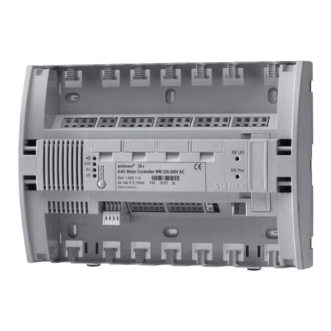
RC200 NEW RUN TIMER
433MHZ RADIO MOTOR CONTROL
NOTE: This equipment LH8TX-S435 and LH8RP-S435 has been tested and found to comply with limits for a class B
digital device, according to part 15 of FCC rules.
These limits are designed to provide reasonable protection against harmful interference to radio communications.
However, there is no guarantee that interference will not occur in a particular installation. If this equipment does
cause harmful interference to radio or television reception, which can be determined by turning the equipment off and
on, the user is advised to try and correct the situation by taking one or more of the following measures:
D Reorient the receiving device
A Increase the distance between the equipment and the receiver
S Connect the equipment to a socket which is on a different branch circuit than the receiver
S Consult your dealer or an experienced radio/TV technician for help
Troubleshooting
Problem: No response from the receiver
Solutions if led PW is OFF - Check fuse
- Conrm that 120V AC is supplied to terminals 3 and 4
Solutions if led PW is ON - Conrm that the receiver code has been memorized (see MEMORIZING
TRANSMITTER CODES WITH THE RECEIVER on reverse side of this page)
- Make sure you have generated a code for that button on the transmitter (see SETTING CODES IN THE
TRANSMITTERS on the reverse side of this page).
Problem: Receiver only switches in one direction
Solutions - Make sure the jumper is in terminals 8-9 if no safety device is used.
- If the jumper is in terminals 8-9 and the receiver still switches in just one direction, the transmitter code may have
been memorized as either an up or down signal. Delete the transmitter’s code from the receiver memory (see
ERASING RECEIVER MEMORY on the reverse side of this page).
Then with dip switch 1 and 2 on, have the receiver memorize the transmitter’s code again (see MEMORIZING
TRANSMITTER CODES WITH THE RECEIVER on the reverse side of this page).
- Check limit settings on the motor.
Problem: Motor stops/receiver turns off before the motor reaches the limit.
Solutions - The timed run on the receiver is set too low. Increase the run time by following the instructions in the
paragraph “Run time programming (SW1) on page 2.
Problem: The receiver will not memorize a code from a button on the transmitter.
Solutions - Make sure the transmitter has generated a code for that button (see SETTING CODES IN THE
TRANSMITTER on the reverse side of this page).
- If the led LD is on continuosly, the receiver memory is full (has 24 codes memorized). Delete some of the codes (see
ERASING RECEIVER MEMORY on the reverse side of this page).
Problem: Range is poor
Solutions - Make sure the receiver is as far as possible from other receivers, metal objects, EMI sources (floresent
lights, transformers, computers, etc...) Try the receiver in different locations if possible before hard wiring.
- If the receiver is mounted in a metal enclosure or in a remote location from where the transmitters will be used with
metal or other dense material in the line of sight, the receiver’s antenna can be remotely located nearer to the area
the transmitters will be used in (see Installation on this page).
Description
The 200 radio control system consists of one or more transmitters and one or more receivers which can be combined
to meet the specic needs of a wide variety of systems.
The 200 control has a highly reliable and secure rolling code system that uses an algorithm to recognize only specic
variations of the original transmitted code. The receiver is able to memorize 24 different codes in its non volatile
memory. This allows a receiver to be activated by multiple transmitters.
Use
The 200 radio control can be used with Type 3.5, Type 5 and Type 6 120V AC SIMU motors. One RC200 is required for
each motor unless used with SIMU group control relays (RI2, RI3, and GI2).
Each RC200 receiver can be controlled individually from 1 channel (1 button on a transmitter) when the code is
programmed into the RC200 in sequencing mode (open-stop-close-stop..). Using dip switch SW1(on/on). Groups of
RC200 receivers can be controlled together by programming one button as an open for all receivers in a group using
dip switch SW1 (on/o) and one button on the transmitter as close using dip switch SW1 (o/on).
Transmitters
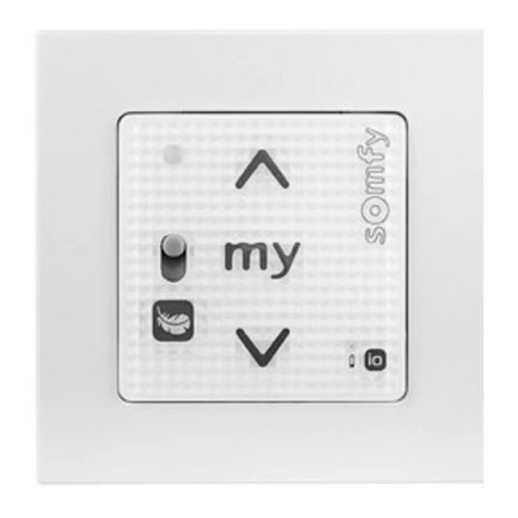
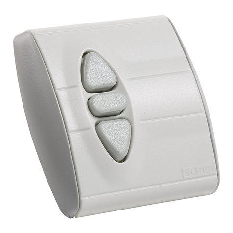
TRAN202 Two channel transmitter 2 Buttons
TRAN204 Four channel transmitter 4 Buttons
Receivers
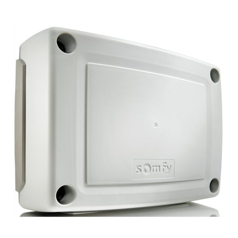
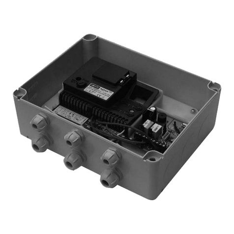
RC200 Motor control receiver in surface external box
Installation
The receiver bracket should be mounted to the wall with the included screws. The receiver can then be slid onto the
bracket. If mounted in an exposed location, the receiver must be mounted with holes marked A and B (see g. 9) facing
down. Receivers should not be mounted within 5 feet of each other. Do not mount the receiver in a metal box, near
metal, or near EMI sources. It is recommended that the range of the unit be tested before permanently wiring the
receiver. If range is poor, often relocating the receiver by a few feet can drastically improve the reception. If the
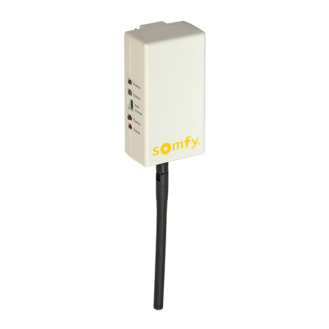
receiver must be installed in a metal box or located in a remote location, the antenna can be remotely located.
Connect the shield of a coaxial cable to terminal 12 and the center conductor to terminal 13. Run the cable to a clear
location near where the transmitter will be used and strip the shielding o the last 17cm (exact length of antenna
supplied with unit).
Electrical connections
- IMPORTANT: For installation by a qualied electrician in accordance with local electrical codes.
- CAUTION: RISK OF ELECTRICAL SHOCK. Disconnect power before installing.
- High voltage 120V AC wires must pass through the holes marked “A” (see g. 9)
- Low voltage wires must pass through the holes marked “B” (see g. 9) and must be routed separately from the high
voltage wires.
Terminals
1-2 Ground (Motor Green)
3 Hot 120V AC 60HZ
4 Neutral
5 Motor direction 1 (Motor Black)
6 Motor direction 2 (Motor Red)
7 Motor common (Motor White)
8-9 N.C. low voltage input for safety device. Jumper must be installed if safety device not used
10-11 N.O. low voltage input with sequencing function (open-stop-close-stop-open...) for single throw, single pole
low voltage switch (Ref# SPBS.W)
12 Antenna ground
13 Antenna connection for 17cm wire supplied with receiver. The antenna can be remotely located using 50 Ohm
coaxial cable as described above in “Installation”
TECHNICAL SPECIFICATIONS
Receiver
- Reception frequency........................................................................................................433.92MHz
- Local emission..........................................................................................................................< 2nW
- Antenna input impedance..................................................................................................50 Ohms
- Sensitivity.......................................................................................................................................1uV
- Power supply............................................................................................................120V AC - 50-60Hz
- Operating temperature range.....................................................................................-20 C / +60 C
Transmitter
- Carrier frequency.............................................................................................................433.92MHz
- Carrier frequency tolerance.................................................................................................+75MHz
- Band width............................................................................................................................> 25kHz
- Power supply (alkaline battery GP23A)......................................................................12V +10%
- Maximum power consumption..................................................................................................25mA
- Operating temperature range....................................................................................-10 C / +55 C
SOMFY SYSTEMS INC
SOMFY NORTH AMERICAN HEADQUARTERS
121 Herrod Blvd.
Dayton, NJ 08810
T: (800) 22-SOMFY (76639)
NJ: (609) 395-1300
F: (609) 395-1776
FLORIDA
1200 SW 35th Ave.
Boynton Beach, FL 33426
T: (800) 22-SOMFY (76639)
F: (561) 995-7502
CALIFORNIA
15301 Barranca Parkway
Irvine, CA 92618-2201
T: (800) 22-SOMFY (76639)
F: (949) 727-3775
SOMFY ULC
SOMFY Canada Division
5178 Everest Drive
Mississauga, Ontario L4W2R4
T: 1-800-66-SOMFY (76639)
CN: (905) 564-6446
F: (905) 238-1491
