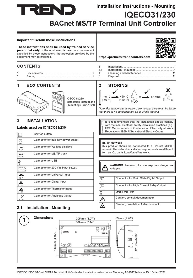
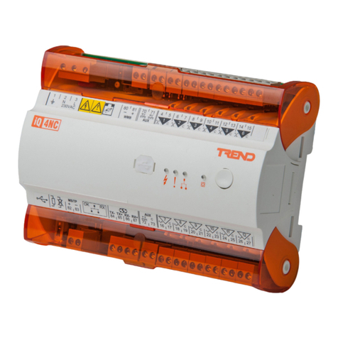
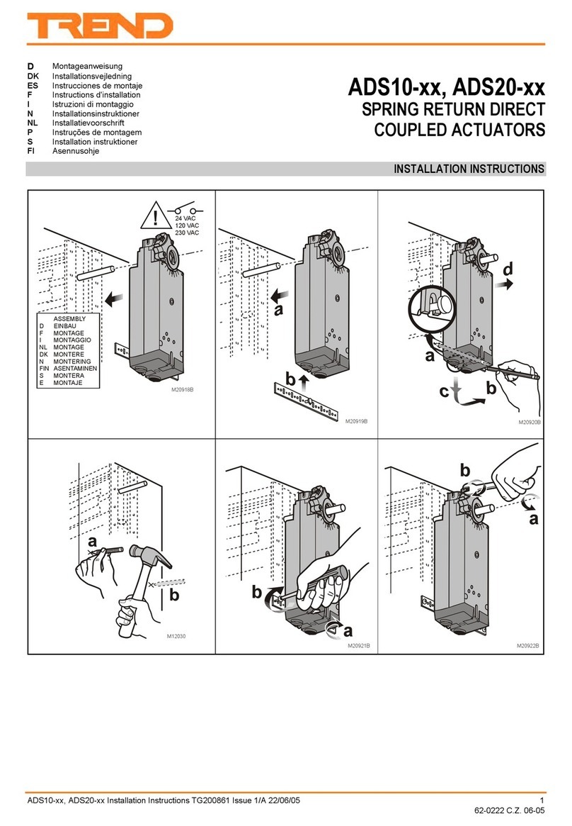
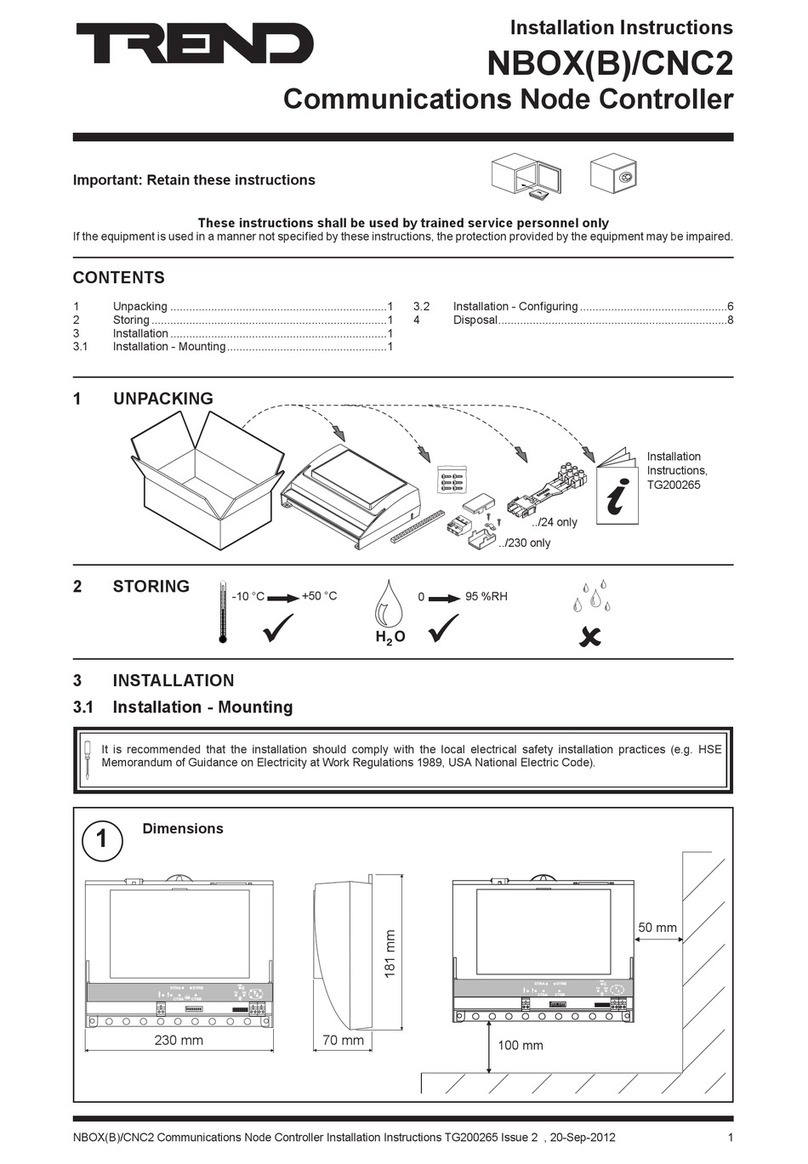
manuals.online logo
Brands
  1. Home
  2. •
  3. Brands
  4. •
  5. TREND
  6. •
  7. Controllers
  8. •
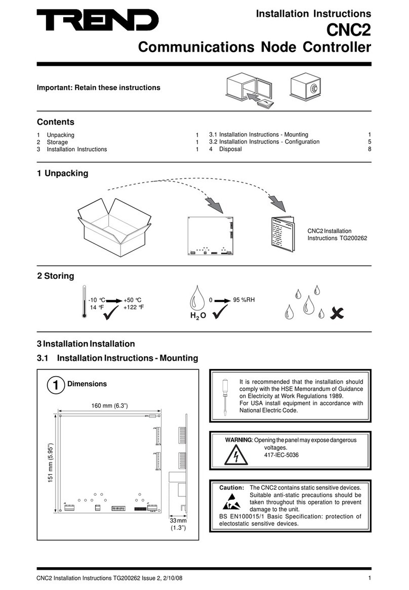
  9. TREND INC2 User manual

TREND INC2 User manual

1
INC2 Installation Instructions TG200231 Issue 2, 22-Mar-2018
Important: Retain these instructions
Installation Instructions
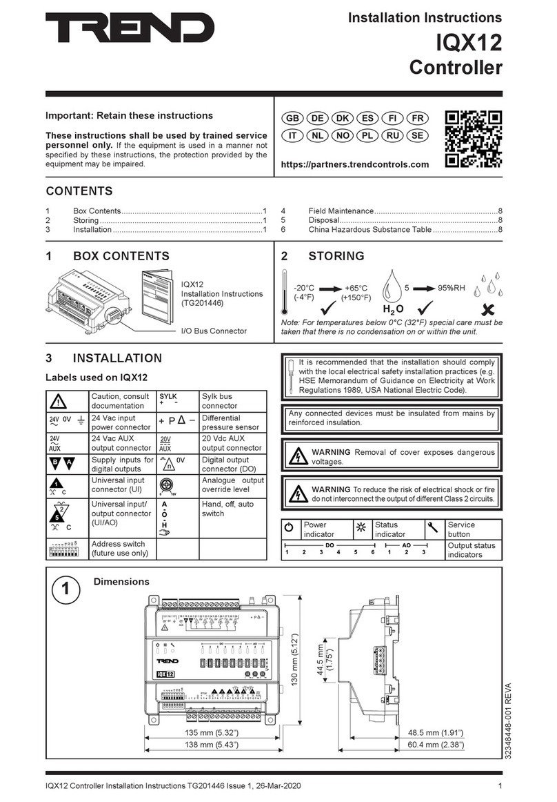
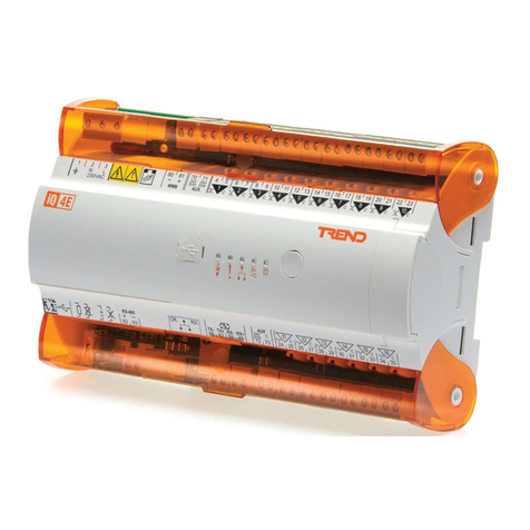
INC2
Internetwork Node Controller
J7
ET1
J16
Dev B
J15
Dev A
J9J8
LanB LanA
2 Storing
3 Installation
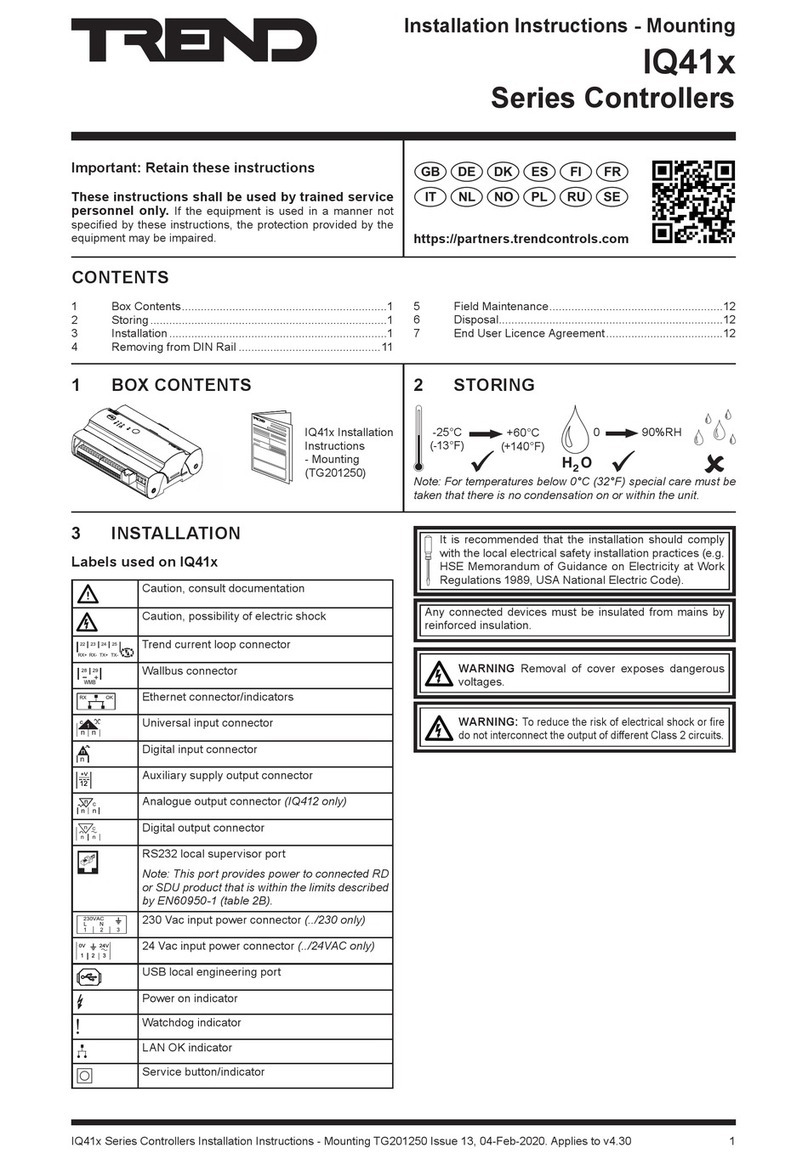
3.1 Installation -Mounting It is recommended that the installation should
comply with the HSE Memorandum of Guidance
on Electricity at Work Regulations 1989.
For USA install equipment in accordance with the
NationalElectricCode.
H O
2
+50 °C
(122 °F)
0
-10 °C
(14 °F)
95 %RH
Installation Instructions,
TG200231
1 Unpacking
Contents
1 Unpacking ...........................................................................1
2 Storage ...............................................................................1
Dimensions
1
3 Installation
3.1 Installation - Mounting .........................................................1
3.2 Installation - Configuration .................................................4
4 Disposal ..............................................................................8
J 7
J 6
v B
J 5
v A
J 9J 8
L a n B L a n A
160 mm (6.3")
151 mm (5.94")
33mm
(1.38")
Caution: The INC2 contains static sensitive devices.
Suitable anti-static precautions should be
taken throughout this operation to prevent
damage to the unit.
BS EN100015/1 Basic Specification: protection of
electostatic sensitive devices.
WARNING:Openingthepanelmayexposedangerous
voltages.
417-IEC-5036
2INC2 Installation Instructions TG200231 Issue 2, 22-Mar-2018
INC2 Installation Instructions
3.1 Installation - Mounting(Continued)
Mount the Node
2The INC2 can be fitted into enclosures and controllers as shown in the table below:
*INC2 board fits with 3 screws in normal node position or
fits in NDP position (if no NDP). Must use NDP position
if RDS fitted.
See appropriate enclosure/controller
installationinstructionsformoredetailsabout
node installation.
151 mm (5.94")
141 mm (5.55")
4 off 4 mm
J 7
J 6
v B
J 5
v A
J 9J 8
L a n B L a n A
J 7
J 6
v B
J 5
v A
J7
J 6
v B
J 5
v A
J9J8
La n B La n A
J 7
J 6
v B
J 5
v A
J 9J 8
L a n B L a n A
a
d
c
H O
2
0°C
(32 °F) +45 °C
(113 °F) 0%RH 95 %RH
b
I N C 2
Requirements
2
INC2/USA:Theunit
is UL rated as
'UL916 accessory
to open energy
management
equipment'.
BBTEN/BTEN 9
+201/+101QI 9
+111QI 9
+131QI 9
x52QI 9*
242/142QI 9
332/132QI 9
Connecting Power
3
J 7
J 6
v B
J 5
v A
J 9J 8
L a n B L a n A
DONOTAPPLY
POWER
0
I
18 Vac
18 Vac
(isolated)
~ ~ 0V
18 18 0
18-0-18 Vac
~ ~ 0V
+24 V
0V
24 Vdc
~ ~ 0V
terminal size 0.5 to 2.5 mm2(14 to 20 AWG)
INC2consumption<=5VA
3
INC2 Installation Instructions TG200231 Issue 2, 22-Mar-2018
Installation Instructions INC2
3.1 Installation - Mounting(Continued)
ConnectingEarth(ground)
4
J 7
J 6
v B
J 5
v A
J 9J 8
L a n B L a n A
WARNING:Thisapparatusmustbeearthed
(grounded)
J 7
J 6
v B
J 5
v A
J 9J 8
L a n B L a n A
Connect Network (Lan A)
5
T
R
T
R
T
R
T
R
TT
RR
X -
X
X + R X - R X +
TRTRTRTR
TT
RR
X
TTRR
X - X + R X - R X +
2 wire
Network Engineering Manual, 92-1735.
additionalterminals
Normally Local Lan dumb/normal switch set to dumb, any address
dumb/normal switch set to normal, address <100
Note that EINCs, INCs and LINCs cannot be on same Lan
Internetwork segment A ifdumb/normal switch set to normal (internetwork
buffer), address >=100
4 wire
(unless RS232 receiver/transmitter Device A being used e.g. leased line modem)
LANA
LANA
polarity
independent
terminal size 0.5 to 2.5 mm2
(14 to 20 AWG)
elbaCduab2k1duab8k4duab6k9duab2k91seriWfo.oN
2819nedleB m0001
)sdy0901(
m0001
)sdy0901(
m0001
)sdy0901(
m007
)sdy567( 2
7029nedleB m0001
)sdy0901(
m0001
)sdy0901(
m0001
)sdy0901(
m005
)sdy545( 2
002/FH/22/1/1/PTmetsysQI
)1678nedleB(
m0001
)sdy0901(
m0001
)sdy0901(
m007
)sdy567(
m053
)sdy083( 2
002/FH/22/2/2/PTmetsysQI
)3278nedleB(
m0001
)sdy0901(
m0001
)sdy0901(
m005
)sdy545(
m052
)sdy072( 4
additionalterminals
J 7
J 6
v B
J 5
v A
J 9J 8
L a n B L a n A
Connect Network (Lan B)
6
T
R
T
R
T
R
T
R
TT
RR
X -
X
X + R X - R X +
TRTRTRTR
TT
RR
X
TTRR
X - X + R X - R X +
2 wire
additionalterminals
4 wire
(unless RS232 receiver/transmitter Device B being used e.g. leased line modem)
Always Internetwork
Network Engineering Manual, 92-1735.
LAN B / IWRK
LAN B / IWRK
polarity independent
terminal size 0.5 to 2.5 mm2
(14 to 20 AWG)
elbaCduab2k1duab8k4duab6k9 2k91
duab
4k83
duab
fo.oN
seriW
2819nedleB m0001
)sdy0901(
m0001
)sdy0901(
m0001
)sdy0901(
m007
)sdy567(
m005
)sdy545( 2
7029nedleB m0001
)sdy0901(
m0001
)sdy0901(
m0001
)sdy0901(
m005
)sdy545(
m053
)sdy083( 2
002/FH/22/1/1/PTmetsysQI
)1678nedleB(
m0001
)sdy0901(
m0001
)sdy0901(
m007
)sdy567(
m053
)sdy083(
m052
)sdy072( 2
002/FH/22/2/2/PTmetsysQI
)3278nedleB(
m0001
)sdy0901(
m0001
)sdy0901(
m005
)sdy545(
m052
)sdy072(
m521
)sdy531( 4
4INC2 Installation Instructions TG200231 Issue 2, 22-Mar-2018
INC2 Installation Instructions
Close Panel/Box
7
J 7
J 6
v B
J 5
v A
3.1 Installation - Mounting(Continued)
INC2/USA: The unit is UL rated as 'UL916 accessory to
open energy management equipment'.
3.2 Installation -Configuration
Switch off and open panel/covers
1
O
I
Set Dumb/Normal switch
2
J 7
J 6
v B
J 5
v A
J 9J 8
L a n B L a n A
A D D R E
O N
D B
R
Norm
Sets Internetwork repeater or Lan/Internetwork gateway
dependent on address (see step 4 below)
Dumb
Sets traditional INC only mode:
(Lan/Internetwork gateway, Lan A
always a Lan, never Internetwork)
e.g.
J 7
J 6
v B
J 5
v A
WARNING: Opening the panel may expose
dangerous voltages.
417-IEC-5036
Caution: The INC2 contains static sensitive devices.
Suitable anti-static precautions should be
taken throughout this operation to prevent
damage to the unit.
BS EN100015/1 Basic Specification: protection of
electostatic sensitive devices.
INC2/USA: The unit is UL rated as
'UL916 accessory to open energy
managementequipment'.
5
INC2 Installation Instructions TG200231 Issue 2, 22-Mar-2018
Installation Instructions INC2
= D INC2
Lan
Lan
/
= D Lan
/
= D
Lan
/
= D
J 7
J 6
v B
J 5
v A
J 9J 8
L a n B L a n A
J 7
J 6
v B
J 5
v A
J 9J 8
L a n B L a n A
Set the INC2 Internetwork Address
(Lan number)
3
A D D R E
O N
D B
R
NOTSET
SET
e.g.
Address = D
if dumb (traditional INC only mode)
address defines Lan number on
Internetwork
(Lan/Internetwork gateway)
if normal
if address < 100, address defines
Lan number on Internetwork
(Lan/Internetwork gateway)
Lan INC2 Inter-
network
Inter-
network
SegmentAINC2 Inter-
network
SegmentB
Address = 2+16+64= 82
if address = > 100, address is for
configuration only
(Internetwork repeater)
BAUD B BAUD A
BAUD B BAUD A
Set Lan A Network Baud Rate
4
Network Baud Rate = R1
(or RS232 to DeviceA)
move link to
set baud rate
(Baud A)
e.g 9k6
(or Device A RS232 baud rate if connected to
RS232 receiver/transmitter)
Baud A
=R1
=R1
=R1
=R1
address 1, 4 to 9, 11 to 114
0, 2, 3, 10 or >119
AB
AB
=R2
=R2
=R2=R2
BAUD B BAUD A
BAUD B BAUD A
Set Lan B Internetwork Baud Rate
5
J 7
J 6
v B
J 5
v A
J 9J 8
L a n B L a n A
Internetwork Baud Rate = R2
(or RS232 to Device B)
move link to
set baud rate
e.g 19k2
(or Device B RS232 baud rate if connected to RS232 receiver/transmitter)
BAUD B BAUD A
or High Baud Rate, 38k4
Note:
needs
extra link
Baud B
(Baud B)
3.2 Installation - Configuration (Continued)
Note that 38k4 baud is only supported if connecting
to other node 2 devices (e.g. 3xtend/EINC L)
communicating over the internetwork. This baud
rate is not supported through the LAN A terminals.
6INC2 Installation Instructions TG200231 Issue 2, 22-Mar-2018
INC2 Installation Instructions
3.2 Installation - Configuration (Continued)
1
1
J 7
J 6
v B
J 5
v A
J 9J 8
L a n B L a n A
J 7
J 6
v B
J 5
v A
J 9J 8
L a n B L a n A
0
I
J 7
J 6
v B
J 5
v A
J 9J 8
L a n B L a n A
Check Node Controller
9
Check input
power
INC2Faulty
b W/DOG
(red)
a PWRON
(green)
Switch On
8
J15 Dev A CABLE/EJ100179A001
not supplied
10 Way,
Female,Molex
links between
pins 2-4, 3-5
Receiver/
Transmitter
25 Way, Female,
'D type'
6Connect to RS232 Device A
if Device A is a RS232 receiver/transmitter
(e.g. leased line modem)
DevB/Modem
Device A CABLE/EJ100179A001
not supplied
10 Way,
Female,Molex
links between
pins 2-4, 3-5
Receiver/
Transmitter
25 Way, Female,
'D type'
7Connect to RS232 Device B
if Device B is a RS232 receiver/transmitter
(e.g. leased line modem)
Device B
J16
Note:Connecting acable toanRS232
connector disables corresponding
Lan communications. Note:ConnectingacabletoanRS232
connector disables corresponding
Lan communications.
black sheath black sheath
Dev A
J15 J16
Dev B/
Modem
O
I
I N C 2
?
I N C 2
?
T T R R
T T R R
J 7
J 6
v B
J 5
v A
J 9J 8
L a n B L a n A
10 Check Lan A
Not if RS232 receiver/transmitter
connected to Dev A
b TXA
(yellow)
a RXA
(yellow)
c OKA
(green)
INC2Faulty Check network cabling
for short circuits with a
multimeter(NOTMegger)
Network Address Invalid
0, 2, 3 or >119
OKA OKA
INC2
Check baud rate. Power up
other nodes until faulty node
is found (OK ). Correct
fault.
LAN A
LAN A
7
INC2 Installation Instructions TG200231 Issue 2, 22-Mar-2018
Installation Instructions INC2
O
I
I N C 2
?
I N C 2
?
J 7
J 6
v B
J 5
v A
J 9J 8
L a n B L a n A
T T R R
T T R R
LAN B / IWRK LAN B / IWRK
11 Check Lan B
Not if RS232 receiver/transmitter
connected to Dev B
b TXB
(yellow)
a RXB
(yellow)
c OKB
(green)
INC2Faulty Check network cabling
for short circuits with a
multimeter(NOTMegger)
Network Address Invalid
0, 2, 3 or >119
OKB OKB
INC2
Check baud rate. Power up
other nodes until faulty node
is found (OK ). Correct
fault.
INC2
QX
3.2 Installation - Configuration (Continued)
13 Configure
Network Engineering Manual 92-1735
IQ Configuration Manual 90-1533
INC2 Data Sheet TA200209
Select from lanmap or set addresses as below:
• If on local Lan, or autodialled Lan, set Lan = 0, address = 126 (Note address used for old INC, Lan 126, address 126, still works)
• If using Internetwork, or autodialled remote Lan, set Lan = switch setting, address = 126
Top Menu
INC2
User addRess
R
e.g. select addRess module
to eXit module having
changed parameter to Quit module and
discard changes
12 Closepanel/covers
J 7
J 6
v B
J 5
v A
Recommend use of SET
INC2/USA: The unit is UL rated as
'UL916 accessory to open energy
managementequipment'.
NotethataPINmay berequiredtomakechangesinconfigurationmode.IfthePINhas beenforgottentheusershouldcontactTrendTechnical
Supportquotingthegeneratornumber(Usermodule)whereuponadefaultPINwillbesupplied.Thiswillonlyworkduringthesameconfiguration
mode session i.e. the utility must not be exited between reading the generator and entering the default PIN. After the PIN is entered a new
PIN should be set up and remembered.
8INC2 Installation Instructions TG200231 Issue 2, 22-Mar-2018
INC2Installation Instructions
WEEE Directive :
At the end of their useful life the packaging,
and product, should be disposed of by a
suitable recycling centre.
Do not dispose of with normal household waste.
Do not burn.
retemara gP nitte nS oitcnu nF oitidno eC toN
sseRdda reifitneD si retcarahcciremunahpla51
sretcarahc*?;{(\/ton-
)AnaL(nalehtrofreifitned yI alpsiD/srosivrepusroftessyawlA
slenaP
krowteNlacoL
otsmrala
sserdd oA t11,9ot4,1sserddaedon
911
tegratmrala2CNIfosserddaedon
smralaAnaLrof
detroperebotsmralaAnaLf 1I
naletome oR t11,9ot4,1rebmunnaL
911
tegratmrala2CNIforebmunnaL
smralaAnaLrof
detroperebotsmralaAnaLf 1I
krowtenretnI
otsmrala
ssErd
d oa t11,9ot4,1sserddaedon
911
tegratmrala2CNIfosserddaedon
smralaBnaLrof
detroperebotsmralaBnaLf 1I
naleTome or t11,9ot4,1rebmunnaL
911
tegratmrala2CNIforebmunnaL
smralaBnaLrof
detroperebotsmralaBnaLf 1I
ePytegaugnalmrala )stigid(9ot k0 rowtenfoegaugnalstceleS
smrala
degnahcebotegaugnalf 2I
res nU iP rebmu nn oitarugifnocnisegnahcstcetorP
edom
teS.)detcetorpnu(knalbsitluafeD
.deriuqerytirucesfipu
rotareneg rebmu Nn IPtluafedrofreb
munmodnar
noitareneg
roferaCinhceTotevig,ylnodaeR
NIPtluafed
3.2 Installation - Configuration (Continued)
14 Settings that may be changed
Set up following parameters if required
1. If set to zero - no alarms reported
2. Language tyPe values:
0=English, 1=Spanish, 2=Finnish, 3=Swedish, 4=Norwegian, 5=Danish, 6=German, 7=Italian, 8=Portuguese, 9=French.
15 Exit Configuration
"Exit from Utility"
16 Check INC2 Operation
If Lan/Internetwork Gateway
If Internetwork Repeater (dumb/normal = normal and address =>100)
LanInternetworkIQINC2INC2Lan
CE
Internetwork
LanLan
Internetwork
Segment
A
Segment
B
INC2INC2INC2
Lan/Internetwork Gateway (INC2 Cor D)
Internetwork Repeater (INC2 E)
IQ
DDC
4Disposal
Please send any comments about this or any other Trend technical
publication to [email protected]
© 2018 Honeywell Technologies Sàrl, E&ES Division. All rights reserved. Manufactured for and on behalf of the Environmental & Energy Solutions
Division of Honeywell Technologies Sàrl, Z.A. La Pièce, 16, 1180 Rolle, Switzerland by its Authorized Representative, Trend Control Systems Limited.
Trend Control Systems Limited reserves the right to revise this publication from time to time and make changes to the content hereof without obligation
to notify any person of such revisions or changes.
Trend Control Systems Limited
St. Marks Court, North Street, Horsham, West Sussex, RH12 1BW, UK. Tel: +44 (0)1403 211888, www.trendcontrols.com

Other TREND Controllers manuals

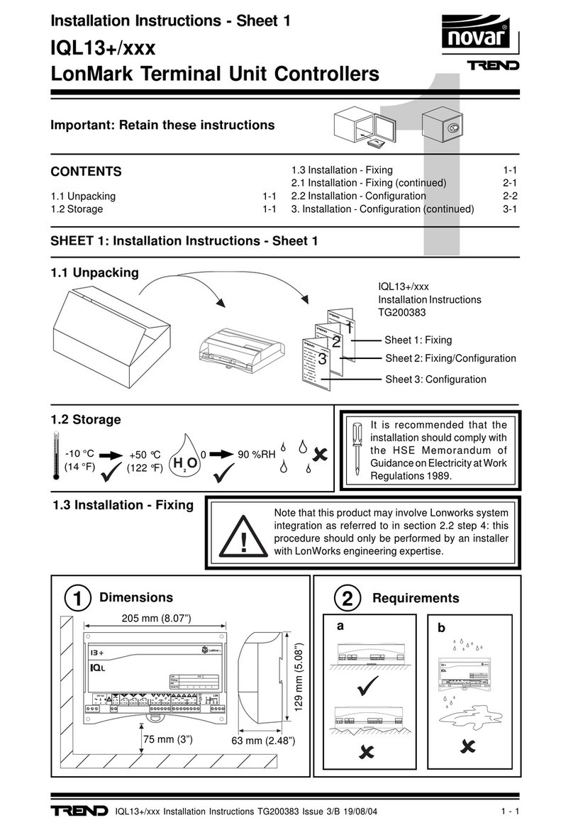
TREND AD05-24 Operation manual

TREND

TREND AD05-24 Operation manual

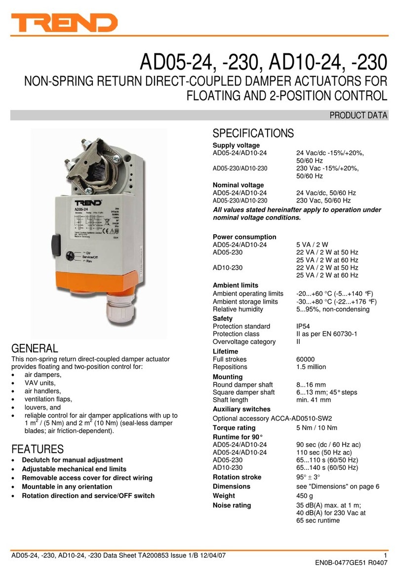
TREND IQ41 Series User manual

TREND

TREND IQ41 Series User manual

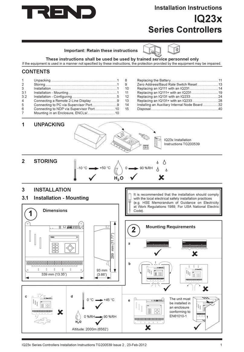
TREND IQ3 series User manual

TREND

TREND IQ3 series User manual

TREND IQ3xcite User manual

TREND

TREND IQ3xcite User manual

TREND AL0620-24-K User manual

TREND

TREND AL0620-24-K User manual

TREND IQX12 User manual

TREND

TREND IQX12 User manual

TREND IQECO31/230 User manual

TREND

TREND IQECO31/230 User manual

TREND IQ422 User manual

TREND

TREND IQ422 User manual

TREND ADS10 Series User manual

TREND

TREND ADS10 Series User manual

TREND IQ4E User manual

TREND

TREND IQ4E User manual

TREND CNC2 User manual

TREND

TREND CNC2 User manual

TREND CNC2 User manual

TREND

TREND CNC2 User manual

TREND IQ23 Series User manual

TREND

TREND IQ23 Series User manual

TREND IQ41 Series User manual

TREND

TREND IQ41 Series User manual

TREND NBOX(B)/CNC2 User manual

TREND

TREND NBOX(B)/CNC2 User manual

TREND IQ422 User manual

TREND

TREND IQ422 User manual

TREND LonMark IQL13+ Series User manual

TREND

TREND LonMark IQL13+ Series User manual

TREND IQ251 User manual

TREND

TREND IQ251 User manual

Popular Controllers manuals by other brands

Haven K Series quick start guide

Haven

Haven K Series quick start guide

AvL Technologies AAQ Handheld Setup & operation guide

AvL Technologies

AvL Technologies AAQ Handheld Setup & operation guide

BayTech PRINT MASTER 706A owner's manual

BayTech

BayTech PRINT MASTER 706A owner's manual

ICM Controls ICM325A Installation, operation & application guide

ICM Controls

ICM Controls ICM325A Installation, operation & application guide

Multiplex ROXXY MSB 45A operating instructions

Multiplex

Multiplex ROXXY MSB 45A operating instructions

KMB NOVAR 2100 operating manual

KMB

KMB NOVAR 2100 operating manual

LIM PressioLIM user manual

LIM

LIM PressioLIM user manual

Camozzi ER100 Series instruction manual

Camozzi

Camozzi ER100 Series instruction manual

Rice Lake 1280 Enterprise Series Operation manual

Rice Lake

Rice Lake 1280 Enterprise Series Operation manual

Crown RPA-RMT installation guide

Crown

Crown RPA-RMT installation guide

Schrack Technik CX plus Series FRACXP06R- user manual

Schrack Technik

Schrack Technik CX plus Series FRACXP06R- user manual

Savant S2 Deployment guide

Savant

Savant S2 Deployment guide

WEISS ER12D-1 Installation & operation instructions

WEISS

WEISS ER12D-1 Installation & operation instructions

Intersil ISL88731EVAL2Z Setup procedure

Intersil

Intersil ISL88731EVAL2Z Setup procedure

Tekmar Snow Melting Control 680 Integration manual

Tekmar

Tekmar Snow Melting Control 680 Integration manual

Vacon 100X series Installation and maintenance manual

Vacon

Vacon 100X series Installation and maintenance manual

Emerson 818-9010 Installation and operation manual

Emerson

Emerson 818-9010 Installation and operation manual

Omnio UPJ230/12 manual

Omnio

Omnio UPJ230/12 manual

manuals.online logo
manuals.online logoBrands
  • About & Mission
  • Contact us
  • Privacy Policy
  • Terms and Conditions

Copyright 2025 Manuals.Online. All Rights Reserved.