Sonel LKZ-710 User manual


INSTRUCTION MANUAL
WIRE TRACER
LKZ-710
Version 1.6 11 March, 2010

Sonel S.A.
2
Wire tracer LKZ-710 is intended to locate electrical cabling embedded in
different materials (concrete, bricks, timber) in buildings. The cables can be de-
tected regardless whether they are live or not.
Tracer’s main features:
•Detection of cables in ceilings, walls and floors,
•Detection of the place of shorted circuits (using an external power source),
•Locating of switches and fuses,
•Identification of cables in an installation.

Sonel S.A. 3
CONTENTS
1
INTRODUCTION....................................................................5
2
SAFETY....................................................................................5
3
PREPARING THE DEVICE FOR WORK...........................6
4
EQUIPMENT DESCRIPTION...............................................7
4.1
T
RANSMITTER
LKN-710 ......................................................7
4.2
R
ECEIVER
LKO-710.............................................................8
4.2.1
Panel..............................................................................8
4.2.2
Sound signals.................................................................9
4.3
L
EADS
.................................................................................10
5
WORKING PRINCIPLES....................................................10
5.1
G
ENERAL
I
NFORMATION
.....................................................10
5.2
T
RANSMITTER
.....................................................................10
5.3
R
ECEIVER
...........................................................................10
5.4
C
LOSED
-C
IRCUIT
M
EASUREMENTS
.....................................11
6
SYSTEM WORKING MODE...............................................12
7
MEASUREMENTS................................................................13
7.1
A
MPLIFICATION
(
SENSITIVITY
)
ADJUSTMENT
......................13
7.2
D
ETECTION OF
C
ABLES IN
C
EILINGS
,
W
ALLS AND
F
LOORS
14
7.2.1
Live Cables..................................................................14
7.3
I
DENTIFICATION OF
F
USES ON THE
D
ISTRIBUTION
B
OARD
..15
7.4
L
OCATING
S
HORT
C
IRCUITS BETWEEN
L
EADS
....................16
7.5
T
RACING THE SHIELDED WIRES
...........................................17
7.6
T
RACING
S
HIELDED
C
ABLES
...............................................18
7.7
T
RACING
W
ATER
P
IPES AND
H
EATING
P
IPELINES
...............18
7.8
T
RACING THE DUCTS
...........................................................19
8
TROUBLE SHOOTING........................................................20
9
POWER SUPPLY ..................................................................20
9.1
B
ATTERIES
..........................................................................20
9.2
R
EPLACEMENT OF
B
ATTERIES IN THE
R
ECEIVER
.................21
10
CLEANING AND MAINTENANCE ...................................21
11
STORAGE ..............................................................................22
12
DECOMMISSIONING AND RECYCLING.......................22

Sonel S.A.
4
13
APPENDICES.........................................................................22
13.1
T
ECHNICAL
S
PECIFICATIONS
...............................................22
13.2
S
TANDARD
A
CCESSORIES
....................................................22
13.3
O
PTIONAL
A
CCESSORIES
.....................................................23
13.4
T
HE
M
ANUFACTURER
.........................................................23

Sonel S.A. 5
1 Introduction
Thank you for choosing our wire tracer. LKZ-710 is a state of the art, high
quality device that is simple and safe to operate. Nevertheless familiarization
with this manual will help you avoid errors and possible problems that might oc-
cur while using the device.
This instruction manual uses three types of warnings. They are framed
texts describing possible threats for a user and for the equipment. Texts that
start with a word “WARNING:” describe situations that can become hazardous if
the instructions are not followed. The word “NOTE!” at the beginning of the
framed text signals a situation where non-adherence to the instruction can
damage the equipment. Other possible problems are signalled by a “Note:” flag.
WARNING:
Before using the device read carefully this manual, follow all occupa-
tional health and safety rules and manufacturer’s recommendations.
WARNING:
LKZ-710 is intended for searching and locating power lines in walls. Us-
ing the device for purposes other then described in this manual can
cause an injury to the operator and/or can damage the device.
WARNING:
LKZ-710 may be used only by qualified personnel who are certified to
work with electrical installations. Operating the instrument by a person
who is not qualified, can result in a hazardous situation and/or can
cause damage to the device.
2 Safety
WARNING:
Using a device that has damaged housing or with leads that have dam-
aged insulation can be a source of a safety hazard.
To ensure proper use and correctness of obtained results adhere to the
following recommendations:
•Before starting to use the device, you have to become thoroughly familiar
with this manual.
•The device should be operated only by persons holding appropriate qualifi-
cations and who attended appropriate occupational health and safety train-
ing.
•It is not acceptable to:

Sonel S.A.
6
⇒use the device that is damaged in any way and is partially or fully inop-
erative,
⇒use leads with damaged insulation,
⇒use the meter stored in inappropriate conditions (e.g. high humidity) for
a prolonged period of time.
•Repairs can be performed by authorised service agents only.
NOTE!
The transmitter is designed to work with a rated voltage of 230V.
Connecting the device to a voltage that exceeds 250VAC can damage
the instrument.
WARNING:
The instrument must not be used with installations or equipment situ-
ated in dangerous environments, e.g. where fire or explosion hazards
exists.
3 Preparing the Device for Work
Before you start locating cables check if the transmitter’s housing and
leads’ insulation are not damaged.
WARNING:
Using leads with damaged insulation can case electrocution.
WARNING:
You must not leave one lead disconnected from the device while the
other one is connected to the tested installation.
You must not leave the device connected to the tested installation with-
out supervision.
WARNING:
Do not use a device that was stored for a prolonged period of time in
unsuitable (e.g. humid) conditions.

Sonel S.A. 7
4 Equipment Description
4.1 Transmitter LKN-710P
1 2
3
4
CAT III 300V
Serial No:
MAX 250 V RMS
LKN-710P
ABN: 45 206 766 437
OUTPUT
POWER
MODE
- LKZ-710
- P-3
Fig. 1. Transmitter of the tracer (panel)
1 test lead
Lead used to connect the transmitter with the tested circuit.
2 test lead
Lead used to connect the transmitter with the tested circuit.
NOTE!
The transmitter is designed to work with a nominal voltage of 230 V.
Using the transmitter with a voltage higher than 250 V AC may damage
the device.
3
OUTPUT
POWER
MODE
button
Setting the output power of the transmitter.
Mode switching.

Sonel S.A.
8
4 LED
Indicates the working mode and power level of the transmitter:
•red colour of shining – LKZ-710 working mode
- LED is blinking slowly – small transmitter power
- LED is blinking quickly – big transmitter power
•green colour of shining – P-3 voltage tester working mode
4.2 Receiver LKO-710
4.2.1 Panel
9
10
11
13
7
6
12
14
8
5
M
M
LKO-710
MODE
TRANSMITTER
Fig. 2. Receiver of the tracer (panel)
5 Head
Contains a magnetic and electric field detector.

Sonel S.A. 9
6 button
Allows to turn the receiver on and off.
7 button
•Decreasing the subrange (sensitivity) of the receiver.
•Press this button in combination with the 8 button to change the
working mode: current or non-contact voltage tester mode.
8 button
•Increasing the subrange (sensitivity) of the receiver.
•Press this button in combination with the 7 button to change the
working mode: current or non-contact voltage tester mode.
9 LED indicator
Shows the subrange of the receiver and the intensity of the magnetic or
electric field.
10 “M” LED
Indicates that the current circuit of the receiver is active.
11 LED
Indicates that the non-contact voltage tester mode is active.
12 LED
Indicates that the battery is discharged.
13 “TRANSMITTER M” DIODE
Indicates detection of the transmitter signal.
14 LED
Indicates detection of the 50/60 Hz electric field from the phase leads (non-
contact voltage tester mode).
4.2.2 Sound signals
Confirmation signals and others:
Single short sound signal
•change of the “sensitivity subrange”
Two short sound signals
•activation or deactivation of the subrange indication
Three short sound signals
•change of the receiver working mode
Single long sound signal (approx. 0.5 s)
•indicates that the lowest or highest subrange has been reached
•indicates that the button is not active

Sonel S.A.
10
4.3 Leads
Crocodile clips and probes provided with the leads can be placed on ca-
ble terminators.
WARNING:
Using damaged leads with the transmitter can be dangerous for the op-
erator of the device.
5 Working Principles
5.1 General Information
LKZ-710 system consists of two components: transmitter and receiver.
The transmitter connected to the circuit being traced generates magnetic („M”
mode) field around the circuit. It is created as a result of a suitably modulated
current flowing through the tested (closed) circuit.
Note:
The transmitter LKN-710P co-operates with the receiver LKO-710 as
well as with voltage tester P-3 (see Manual LKN-710P).
The transmitter placed alongside the tested circuit detects the modulated
field and notifies the user. Mapping of the circuit (cable) route or its defects is
possible through observation of the detected signal intensity level.
5.2 Transmitter
Electromagnetic signals broadcast by the transmitter are appropriately
modulated. Therefore it is possible to differentiate between them and other sig-
nals that may be present in the tested circuit or its immediate vicinity. The 3
OUTPUT
POWER
MODE
button can be also used to set (also sequentially) one of two power levels:
•low – LED 4 is blinking red slowly
•high – LED 4 is blinking red quickly
•P-3 voltage tester working mode – LED 4 is shining green
LED remaining switched off signals that the tested circuit is dead or that
the transmitter is damaged.
5.3 Receiver
Receiver’s antenna 5 hides two sensors: an electric field detector and a
magnetic field detector. The electric field detector has an aerial shaped in a
form of a metal plate. The magnetic field detector has an aerial shaped as a
coil. The way the aerials are located (Fig. 3) influences directional characteris-
tics of the receiver.

Sonel S.A. 11
An electric field detector’santenna
Amagnetic fielddetector’s antenna
Fig.3 Location of sensors in receiver’s antenna
Electric or magnetic field strength is indicated by the LED indicator 9
“deflection” (blinking LED). Sensitivity of the receiver is increased with 8
button and decreased with 7 button. Pressing one of the two buttons cau-
ses litting of LEDs illustrating currently used sensitivity range and the next
pressing – its increasing or decreasing.
Receiver’s work mode is switched sequentially by simultaneous pressing
the 7 and 8 buttons which is accompanied by LED 10 Mor 11
being lit.
The LED 13 TRANSMITTER M is lit when the receiver indicates the
transmitter’s signal.
In the non-contact neon mode the receiver can detect if the tested line is
live and can also locate a live cable. The receiver detects an electric field
50/60Hz displaying its strength on the LED gauge 9 and after exceeding cer-
tain level it turns on the 14 . In this mode the switching of ranges does not
work.
5.4 Closed-Circuit Measurements
Measurements can be performed in a closed circuit provided that a cur-
rent flow can be induced in the circuit. This is the case in a healthy line with
line’s voltage of 230V (the circuit is closed by a transformer) and also in a
shorted line, using the external power source. In all described situations the de-
tection is done by evaluating the magnetic component of the field. Fig.4 illus-
trates the direction of the magnetic field lines around the cable in which the
modulated current flows, and the placement of the receiver allowing for the
highest possible intensity of the received signal.
A
B
C
MODEZOOMUIUTIT
LK O- 70 0
D
Fig.4 Magnetic field detection

Sonel S.A.
12
Directional properties of the receiver can be observed when we try to
change its position in relation to the cable in directions indicated by the arrows.
Swinging the receiver only in directions “A” does not change the signal level
since the magnetic field detector does not change is position in relation to the
magnetic field lines. On the other hand, rotating the receiver around its axis (ar-
row “C”) will cause gradual signal deterioration until it disappears when rotating
the device by 90º. Similarly, when swinging the receiver in direction “D” (around
the axis of the receiver’s aerial). Also moving the receiver away from the cable
(“B”) will weaken the signal as a result of a decrease in field’s strength with an
increase of the distance.
For a 2-core cable in which the current flows through one of the cores in
one direction and in the opposite direction through the other core, the magnetic
field strength is much lower than in a single-core cable since the fields gener-
ated by the cores cancel each other out. The greater the distance between the
cores, the stronger is the magnetic field. This phenomenon is utilised for detect-
ing all sorts of inconsistencies in power lines e.g. cable boxes, switches, stub
cables, cable ducts constrictions etc.
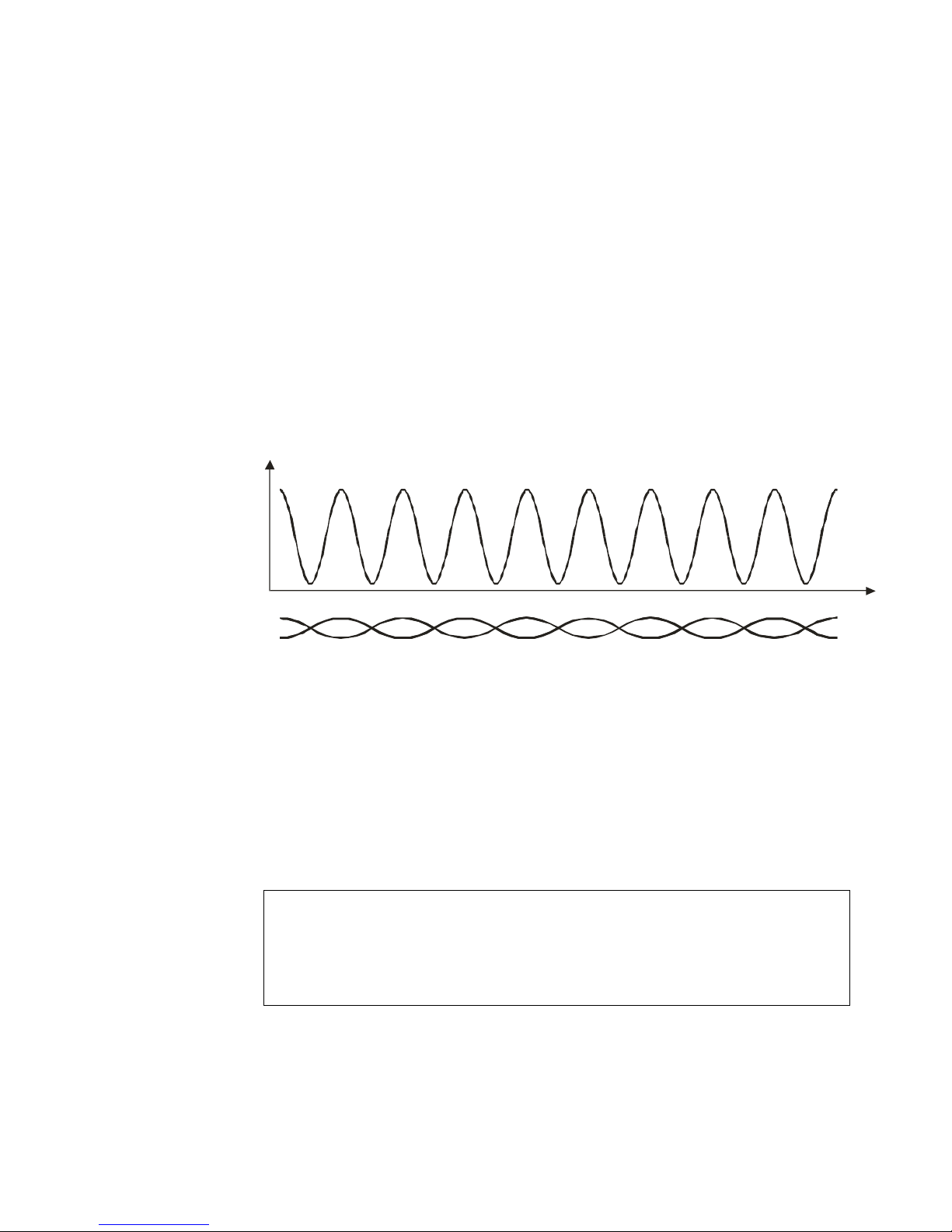
A different field distribution is created around a twisted pair cable. It is not
uniform and changes periodically depending on the relative position of the cores
(Fig. 5). It has to be taken into account when tracking a cable or locating cable
faults.
Twisted pair cable
Magnetic field intensity
Cable length
Fig.5 Magnetic field distribution around a twisted pair cable
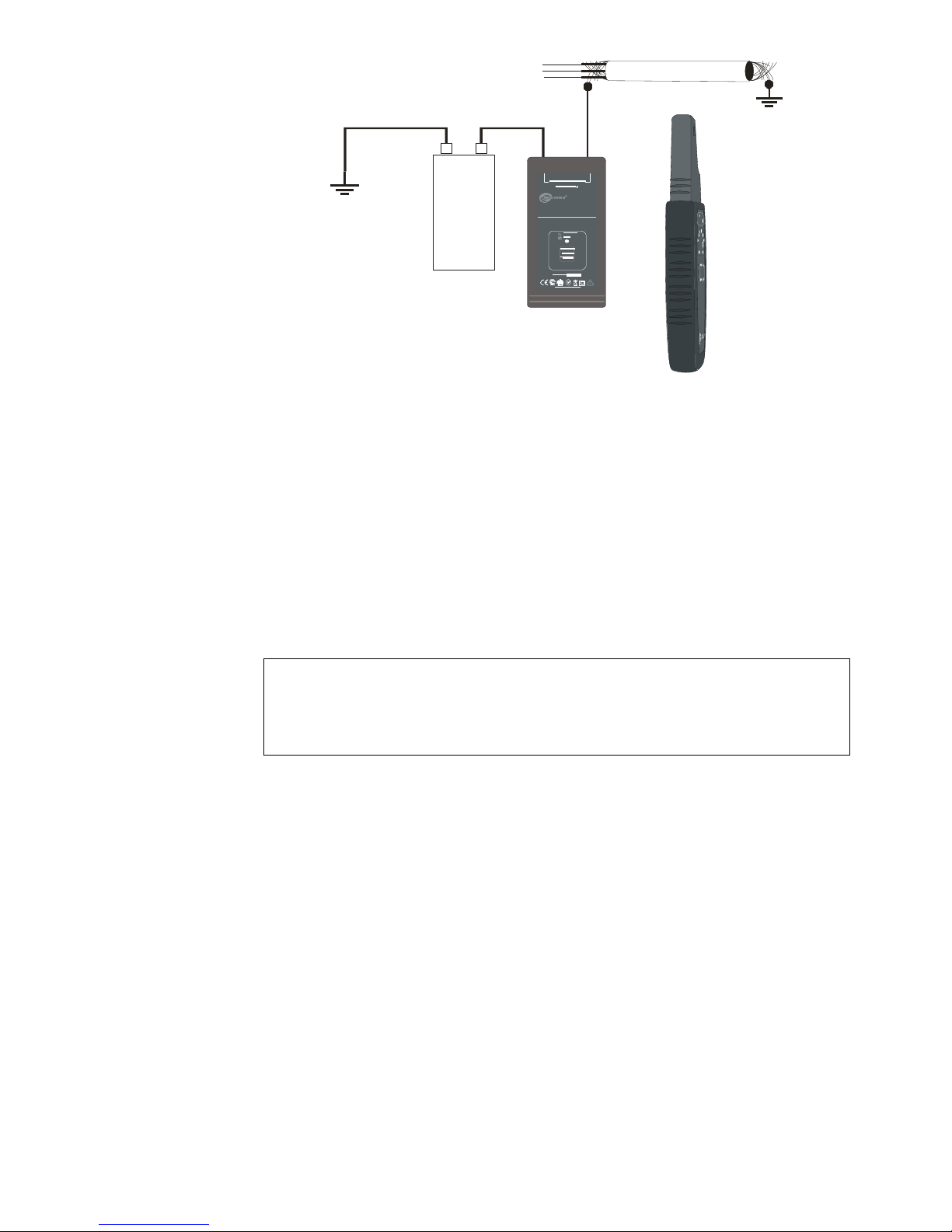
6 System working mode
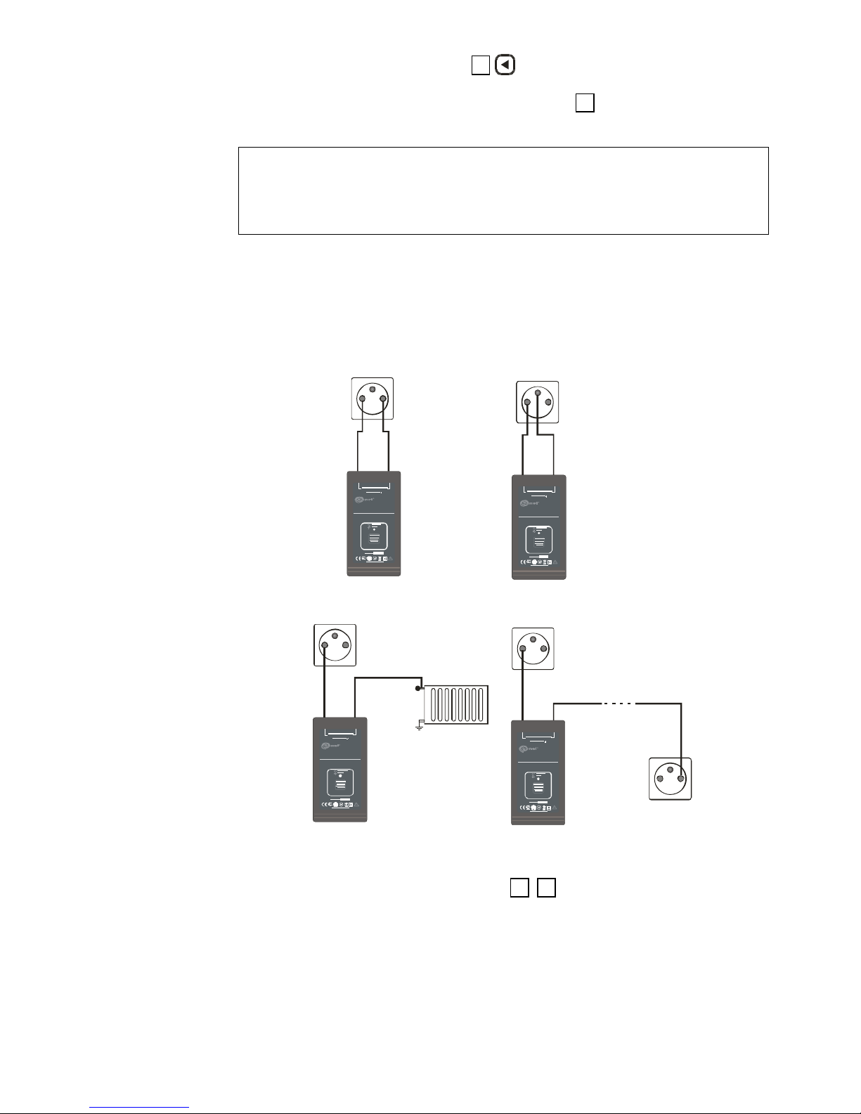
The system operates in the “M” current mode and can be used with un-
damaged leads under a voltage of 230 V AC or in closed circuits (for example,
shorted leads). It uses external direct current (minimum 12 V) or an alternating
current source (minimum 24 V).
NOTE!
The transmitter is designed to work with the rated voltage of 230V.
Connecting the device to a voltage that exceeds 250VAC can damage
the instrument.
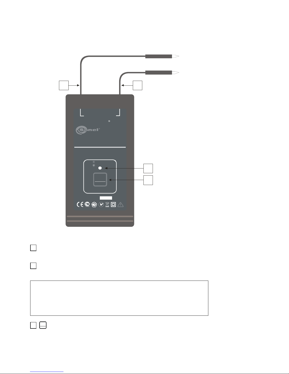
One of the transmitter’s output terminals is connected to the phase wire of
the tested cable and the other one to the neutral wire. The voltage that exists in
this circuit is used by the transmitter to generate a current signal (max 20mA) in
a form of high frequency impulses with the amplitude modulated by a lower fre-
quency signal distributed over the time in the specific way. The magnetic com-
ponent of the field generated in this way is then detected by the receiver.

Sonel S.A. 13
7 Measurements
NOTE!
The transmitter is designed to work with the rated voltage of 230V.
Connecting the device to a voltage that exceeds 250VAC can damage
the instrument.
WARNING:
You must not leave one lead disconnected from the device while the
other one is connected to the tested installation.
You must not leave the device connected to tested installation without
supervision.
WARNING:
Always connect the transmitter to the ground first and only than to the
phase wire.
Note:
It is necessary to use a power source strong enough to generate
a proper test current. When the current is generated, the 4 LED
flashes.
Note:
In objects with working appliances, the receiver may display a level of
noise signals. You should take into account the signal level only if the
LED 13 „M” is on.
Note:
You have to recon with incorrect readings due to induction of current
signals in closed circuits in buildings (window frames, metal frame-
work, concrete reinforcements etc.).
7.1 Amplification (sensitivity) adjustment
The amplification level of the receiver is adjusted gradually, by choosing
one of six sensitivity subranges. The adjustment is performed with buttons 7
and 8 .Pressing one of the buttons will light the 9 LED at the begin-
ning of the scale to indicate the currently used range (the number of lit LEDs in-
dicates the number of the selected subrange). The LEDs will automatically ex-
tinguish after approx. 2 seconds. To increase the sensitivity (amplification),
press the 8 button when LEDs indicating the current sensitivity are lit; to

Sonel S.A.
14
decrease the sensitivity, press the 7 button when LEDs indicating the cur-
rent sensitivity are lit. The sensitivity should be decreased when the rightmost
LED indicating the signal strength on the scale 9 will be lit; the sensitivity
should be increased when the leftmost LED will light.
Note:
The rightmost LED indicates subrange lights stronger than other LEDs,
which helps to see it in strong external light.
7.2 Detection of Cables in Ceilings, Walls and
Floors
7.2.1 Live Cables
LN
PE PE
LN
LN
PE
PE
LN
PE
LN
LKN- 710P
LKN-710P
LKN- 710P LK N- 710P
Fig.6 Detection of cables – different ways of connecting the transmitter
•Connect one of the transmitter leads 1 , 2 to the earthing system.

Sonel S.A. 15
Note:
To avoid the field compensation effect when the current flows through
two cores of the cable in opposite directions, you need to use ground-
ing (the earth or the neutral wire) situated in the remote power socket
or to connect to earthed metal water pipe or to a heating pipeline (Fig.
6). In some cases, e.g. when the return current can flow through
earthed structural elements of the building, it can be more beneficial
for unambiguous localization of the cable to connect both leads of the
transmitter to one power point.
•Connect the second lead to the phase lead in the socket, switch, etc. (Fig.
6).
•After the transmitter is connected, the 4 LED should flash.
•Use the 3
OUTPUT
POWER
MODE
button to set the proper level of the transmitter output sig-
nal.
•Press the 6 button to turn on the receiver; the current mode (“M”) will
be active.
•Move the head of the receiver along the tested wire (Fig. 4) in the direction
the signal is getting stronger; select the proper sensitivity of the receiver
(see 7.1).
7.3 Identification of Fuses on the Distribution
Board
•Connect one of the transmitter leads 1 or 2 to the neutral lead of the
socket; connect the second lead of the transmitter to the phase lead.
•After the transmitter is connected, the 4 LED should flash.
•Use the 3
OUTPUT
POWER
MODE
button to set the proper level of the transmitter output sig-
nal.
•Press the 6 button to turn on the receiver; the current mode (“M”) will
be active.
•Move the head of the receiver along the tested wire (Fig. 4) in the direction
the signal is getting stronger; select the proper sensitivity of the receiver
(see 7.1).
•Move the head from one fuse to another and select the proper sensitivity of
the receiver (see 7.1); locate the appropriate fuse according to the maxi-
mum signal strength (Fig. 7).

Sonel S.A.
16
L N
PE
L N
PE
M
M
LKO-710
TRYB
LKN-710P
Fig.7 Identification of circuit breakers in a distribution board
Note:
Because modern fuses, and in particular RCDs, have inside one or more
coils it may be necessary to try different ways of positioning the receiver
and a number of attempts to locate a fuse will be required.
7.4 Locating Short Circuits between Leads
WARNING:
Before a measurement check if the cables are live. If yes then cut off
the power.
•Connect one of the transmitter leads ( 1 or 2 )to one of the shorted wires;
connect the second transmitter lead to the power source (min. 12 V DC or
24 V AC) (Fig. 8).
•After the transmitter is connected, the 4 LED should flash.
•Use the 3
OUTPUT
POWER
MODE
button to set the proper level of the transmitter output sig-
nal.
•Press the 6 button to turn on the receiver; the current mode (“M”) will
be active.
•Move the head of the receiver along the tested wire (Fig. 4) in the direction
the signal is getting stronger; select the proper sensitivity of the receiver
(see 7.1). The signal strength decreases or the signal disappears when
moving from the point of shorting.

Sonel S.A. 17
U
I
UI
L
KO
-
70
0
Power source
DC
or 24V AC
min. 12V
LKN-710P
Fig.8 Locating a short circuit in a cable
Note:
For increased accuracy of the short circuit localization the test should
be repeated starting from the other end of the cable.
When locating a short circuit point in a twisted pair cable you need to
take into account heterogenous field distribution along the cable
(Fig.5).
7.5 Tracing the shielded wires
•Connect one of the transmitter leads ( 1 or 2 ) to the shield of the wire,
and the second lead to the grounded source of the direct or alternating cur-
rent (Fig. 9).
•After the transmitter is connected, the 4 LED should flash.
•Use the 3
OUTPUT
POWER
MODE
button to set the proper level of the transmitter output sig-
nal.
•Press the 6 button to turn on the receiver; the current mode (“M”) will
be active.
•Move the head of the receiver along the tested wire (Fig. 4) in the direction
the signal is getting stronger; select the proper sensitivity of the receiver
(see 7.1).

Sonel S.A.
18
U
I
UI
L
K
O-
70
0
Battery LKN-710P
Fig. 9 Tracing the shielded wires
7.6 Tracing Shielded Cables
Procedure is the same as the one described in section 7.2. You only have
to take into account that in steel ducts the signal is subject to attenuation. On
the other hand aluminium and plastic ducts have no impact on the signal level.
7.7 Tracing Water Pipes and Heating Pipelines
The procedure is the same as for locating cables in a closed circuit
(Fig.10 i 11).
Note:
You need to take into account that the current flowing through a metal
pipe to the earth will do so using all possible routes.
Table of contents
Other Sonel Measuring Instrument manuals

Sonel
Sonel MIC-5001 User manual

Sonel
Sonel DIT-130 User manual

Sonel
Sonel MIC-10 User manual

Sonel
Sonel WMGBMZC304F User manual

Sonel
Sonel MPI-520 User manual

Sonel
Sonel TDR-410 User manual

Sonel
Sonel MRU-200 User manual

Sonel
Sonel WMGBCMP3kR User manual

Sonel
Sonel LXP-10B User manual

Sonel
Sonel WMGBMRU120 User manual
Popular Measuring Instrument manuals by other brands

Extech Instruments
Extech Instruments MO265 user guide

Shodex
Shodex CLNpak EV-200 Operation manual

Apera Instruments
Apera Instruments TN500 instruction manual

Lovibond
Lovibond PoolDirect Instruction and operation manual

Allen-Bradley
Allen-Bradley 1444-TSCX02-02RB user manual

Amprobe
Amprobe TMA-21HW user manual