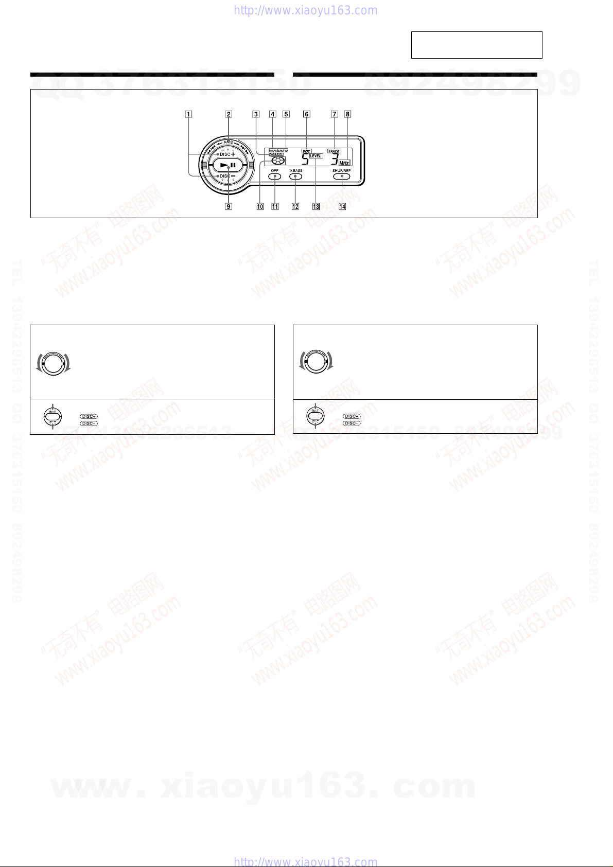
6
Listening to a CD
1
Turn on the FM tuner of your car audio.
2
Tune in the selected transmitting
frequency*with the FM tuner of your car
audio.
*The frequency of the unit is set to 88.3 MHz at
the factory.
You can change the frequency. (See “Changing
the transmitting frequency” below.)
3
Press u.
CD playback starts.
4
Adjust the volume with the volume control
on your car audio.
All the tracks play from the beginning.
Stopping CD play
Press (OFF).
Notes
•When CD playback stops, you may hear some noise
from the speakers. To prevent this from happening,
turn the volume down before stopping CD playback.
•If you turn off the ignition switch of your car
without stopping CD playback, it will automatically
resume CD playback from where it was stopped
when you turn on the ignition switch again.
Listening to the radio or a tape
Be sure to stop CD playback before you start
listening to the radio or a tape.
Note
Be sure to stop CD playback, otherwise there may be
some interference with radio reception.
Playing tracks in random order
— Shuffle Play
You can select:
•SHUF 1–to play the tracks on the current disc in
random order.
•SHUF 2–to play all the discs in random order.
Press (SHUF/REP) repeatedly until the
desired setting appears (SHUF1 or SHUF2).
After five seconds, shuffle play starts.
Each time you press (SHUF/REP), the display
changes as follows:
BSHUF 1 BSHUF 2 BREP 1
Cancel (SHUF off) bREP 2 b
To go back to the normal playback mode, press
(SHUF/REP) repeatedly until the “SHUF” or
“REP” indication disappears.
Playing tracks repeatedly
— Repeat Play
You can select:
•REP 1–to repeat the track.
•REP 2–to repeat the disc.
Press (SHUF/REP) repeatedly until the
desired setting appears (REP1 or REP2).
After five seconds, the repeat play starts.
Each time you press (SHUF/REP), the display
changes as follows:
BSHUF 1 BSHUF 2 BREP 1
Cancel (REP off) bREP 2
To go back to the normal playback mode, press
(SHUF/REP) repeatedly until the “REP” or
“SHUF” indication disappears.
Boosting the bass sound
— D-bass
You can enjoy a powerful bass sound. The D-bass
function boosts the low frequency signal.
You can hear the bass line more clearly even while
the vocal volume remains the same. You can
emphasize and adjust the bass sound easily with
the D-BASS button.
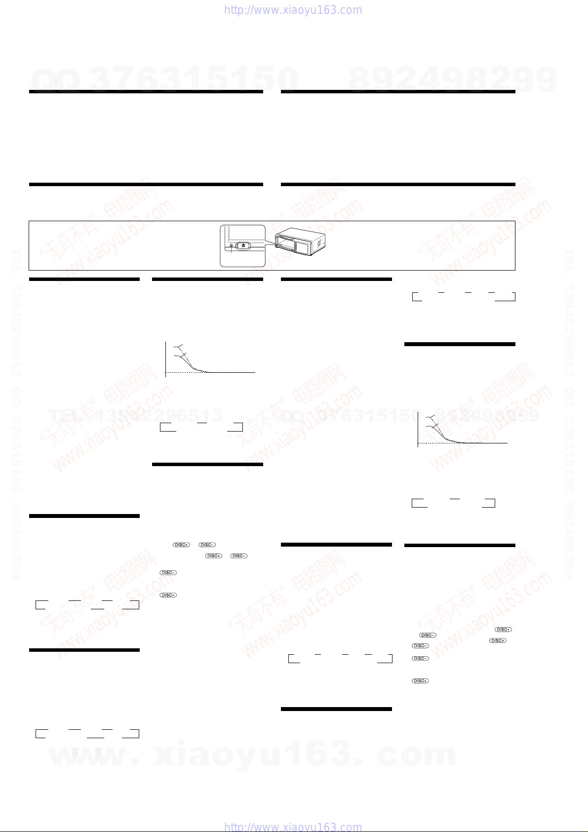
0dB
D-BASS 2
D-BASS 1
Adjusting the bass curve
Press (D-BASS) repeatedly to select the
desired bass curve.
As the D-BASS number increases so does the
effect.
BD-BASS 1 BD-BASS 2
Cancel (D-BASS off)b
Note
Setting the output level from 4 to 5, the amount of
bass boost decreases to avoid distortion.
Changing the transmitting frequency
Because this unit processes CD playback sound
through an FM tuner, there may be interference
noise during CD playback. In such a case, change
the frequency of the modulated RF signal
transmitted from the unit. The initial setting is
88.3 MHz.
1
Press (SHUF/REP) for two seconds until
frequency appears.
2
Press or repeatedly to
select the frequency.
Each time you press or , the
frequencys changes as follows:
: 88.3 MHz t 89.9 MHz t 89.7 MHz
t 89.5 MHz t 89.3 MHz t 89.1
MHz t 88.9 MHz t 88.7 MHz t
88.5 MHz t 88.3 MHz
: 88.3 MHz t 88.5 MHz t 88.7 MHz
t 88.9 MHz t 89.1 MHz t
89.3 MHz t 89.5 MHz t 89.7 MHz
t 89.9 MHz t 88.3 MHz
3
Press (SHUF/REP) for two seconds.
Notes
•When you change the transmitting frequency on the
unit, be sure to tune your FM tuner to the newly
selected one.
•Press uon the wired remote before changing the
frequency if the power to the unit is turned off.
Operation Fonctionnement
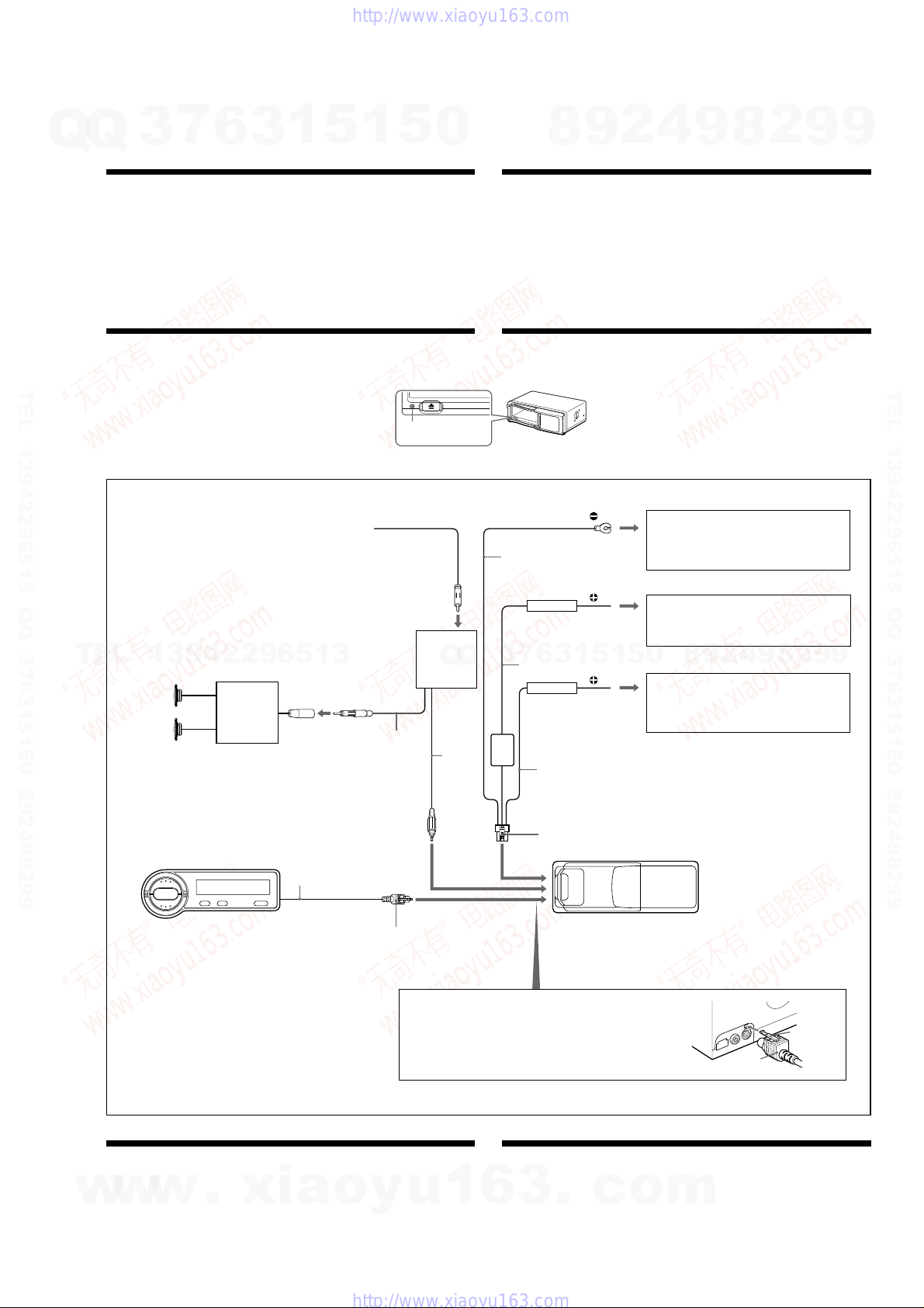
Precautions
•This unit cannot be used with a car audio without an FM tuner.
•If your car was parked in direct sunlight resulting in a considerable rise in temperature inside the car,
allow the unit to cool off before operating it.
•If no power is being supplied to the unit, check the connections first. If everything is in order, check the
fuse.
•Avoid installing the CD changer and wired remote in places:
— subject to temperature exceeding 55°C (131°F).
— subject to direct sunlight.
— near heat sources (such as heaters).
— exposed to rain or moisture.
— exposed to excessive dust or dirt.
— subject to excessive vibration.
Précautions
•Cet appareil ne peut être utilisé avec un autoradio sans syntoniseur FM.
•Si votre voiture est parquée en plein soleil, provoquant ainsi une augmentation considérable de la
température dans l habitacle, laissez l appareil refroidir avant de l utiliser.
•Si l appareil n est pas alimenté, vérifiez d abord les connexions. Si tout est en ordre, contrôlez le fusible.
•Evitez d installer le changeur de CD et la télécommande à fil à un endroit :
— où la température peut dépasser 55°C (131°F),
— en plein soleil,
— près d une source de chaleur (comme un chauffage),
— exposé à la pluie ou à l humidité,
— poussiéreux ou sale,
— exposé à des vibrations fortes.
Resetting the unit
Before operating the unit for the first time or after replacing the car battery, you must reset the unit. Press
the reset button with a pointed object, such as a ball-point pen, etc.
Réinitialisation de l’appareil
Avant la première mise en service de cet appareil ou après avoir remplacé la batterie de la voiture, vous
devez réinitialiser l appareil.
Appuyez sur la touche de réinitialisation à l aide d un objet pointu comme un stylo à bille, etc.
Lecture d’un CD
1
Mettez sous tension le syntoniseur FM de
votre autoradio.
2
Syntonisez la fréquence de transmission*
sélectionnée avec le syntoniseur FM de
votre autoradio.
*La fréquence de l’appareil est réglée par défaut
sur 88,3 MHz.
Vous pouvez changer la fréquence. (Voir
“Changement de la fréquence de
transmission” ci-dessous.)
3
Appuyez sur u.
La lecture du CD démarre.
4
Réglez le volume àl’aide de la commande
du volume de votre autoradio.
Toutes les plages sont reproduites à partir du
début.
Pour arrêter la lecture d’un CD
Appuyez sur (OFF).
Remarques
•Lorsque vous arrêtez la lecture d’un CD, il se peut
que vous entendiez des parasites dans les haut-
parleurs. Pour éviter ce phénomène, baissez le
volume avant d’arrêter la lecture du CD.
•Si vous coupez le contact de votre voiture sans
arrêter la lecture du CD, celle-ci reprendra
automatiquement làoùelle a étéinterrompue
lorsque vous remettrez le contact.
Ecouter la radio ou une cassette
Arrêtez la lecture du CD avant d écouter la radio
ou une cassette.
Remarque
Si vous n’arrêtez pas la lecture du CD, des
interférences risquent de se produire avec la réception
radio.
Lecture des plages dans un ordre
quelconque
— Lecture aléatoire
Vous pouvez sélectionner:
•SHUF 1–pour reproduire les plages du disque
en place dans un ordre quelconque.
•SHUF 2–pour reproduire tous les disques dans
un ordre quelconque.
Appuyez plusieurs fois sur (SHUF/REP)
jusqu’à ce que le réglage souhaité
apparaisse (SHUF1 ou SHUF2).
La lecture aléatoire commence dans les cinq
secondes qui suivent.
A chaque pression sur (SHUF/REP), l affichage
change de la façon suivante:
BSHUF 1 BSHUF 2 BREP 1 BREP 2
Annulation (SHUF hors service) b
Pour revenir à la lecture normale, appuyez
plusieurs fois de suite sur (SHUF/REP) jusqu à
ce que l indication “SHUF” ou “REP”
disparaisse.
Répétition de plages
— Lecture répétée
Vous pouvez sélectionner:
•REP 1–pour répéter une plage.
•REP 2–pour répéter tout un disque.
Appuyez plusieurs fois sur (SHUF/REP)
jusqu’à ce que le réglage souhaité
apparaisse (REP1 ou REP2).
La lecture répétée commence dans les cinq
secondes
ui suivent.
Reset button
Touche de
réinitialisation
A chaque pression sur (SHUF/REP), l affichage
change de la façon suivante:
BSHUF 1 BSHUF 2 BREP 1 BREP 2
Annulation (REP hors service) b
Pour revenir à la lecture normale, appuyez
plusieurs fois de suite sur (SHUF/REP) jusqu à
ce que l indication “REP” ou “SHUF”
disparaisse.
Renforcement des graves
— D-bass
Vous pouvez exploiter des graves puissantes. La
fonction D-bass renforce les signaux de basse
fréquence.
Vous entendez plus distinctement les graves,
même si le volume de la partie vocale reste au
même niveau. Vous pouvez renforcer et ajuster
les graves à l aide de la touche D-BASS.
0dB
D-BASS 2
D-BASS 1
Réglage de la courbe des graves
Appuyez plusieurs fois de suite sur
(D-BASS) pour sélectionner la courbe des
graves voulue.
L effet s intensifie à mesure que la valeur D-
BASS augmente.
BD-BASS 1 BD-BASS 2
Annuler (D-BASS off) b
Remarque
En modifiant le niveau de sortie de 4 à5, le degré
d’accentuation du grave diminue afin d’éliminer toute
distcasion.
Changement de la fréquence de
transmission
Comme cet appareil traite le son de lecture CD via
un syntoniseur FM, il se peut qu il y ait des
interférences durant la lecture du CD. En pareil
cas, changez la fréquence du signal RF modulé
transmis par l appareil. Le réglage initial est de
88,3 MHz.
1
Appuyez sur (SHUF/REP) pendant deux
secondes jusqu’à ce que la fréquence
apparaisse.
2
Appuyez plusieurs fois de suite sur
ou pour sélectionner la fréquence.
Chaque fois que vous appuyez sur ou
, la fréquence change dans l ordre
suivant :
: 88.3 MHz t 89.9 MHz t 89.7 MHz
t 89.5 MHz t 89.3 MHz t 89.1
MHz t 88.9 MHz t 88.7 MHz t
88.5 MHz t 88.3 MHz
: 88.3 MHz t 88.5 MHz t 88.7 MHz
t 88.9 MHz t 89.1 MHz t
89.3 MHz t 89.5 MHz t 89.7 MHz
t 89.9 MHz t 88.3 MHz
3
Appuyez sur (SHUF/REP) pendant deux
secondes.
Remarques
•Si vous changez la fréquence de transmission de
l’appareil, n’oubliez pas de syntoniser votre
syntoniseur FM sur la nouvelle fréquence
sélectionnée.
•Appuyez sur la touche ude la télécommande
filaire avant de changer la fréquence si l’appareil
n’est pas sous tension.
Level
Frequency (Hz)
Niveau
Fréquence (Hz)
w
w
w
.
x
i
a
o
y
u
1
6
3
.
c
o
m
Q
Q
3
7
6
3
1
5
1
5
0
9
9
2
8
9
4
2
9
8
T
E
L
1
3
9
4
2
2
9
6
5
1
3
9
9
2
8
9
4
2
9
8
0
5
1
5
1
3
6
7
3
Q
Q
TEL 13942296513 QQ 376315150 892498299
TEL 13942296513 QQ 376315150 892498299
http://www.xiaoyu163.com
http://www.xiaoyu163.com